Solax Triple Power T-BAT H 5.8 User manual
Quick Installation Guide
—— Triple Power Lithium-ion Battery
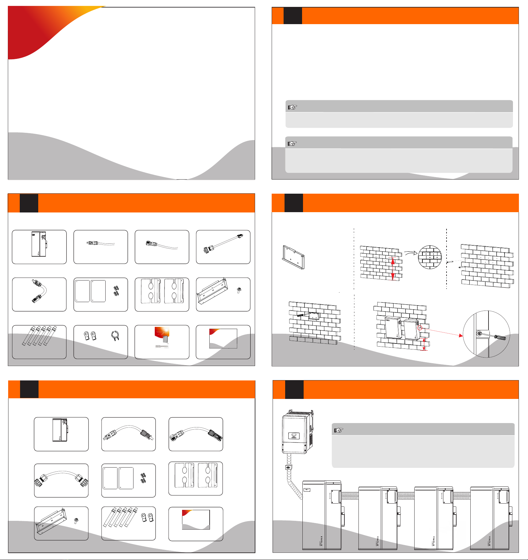
Packing List (T-BAT H 5.8)
I
III
Note: The quick installation guide describes installation steps briefly. If you have any questions during
the installation, please refer to the USER MANUAL which is enclosed to T-BAT H 5.8 for more information.
II
Battery Installation
IV
Overview of Installation
V
Quick installation guide*1
Quick Insta lla tio n Guide
—— Triple Power Lithum-ion Battery
Make sure that the installation location meets the following conditions:
ŸThe building is designed to withstand earthquakes
ŸThe location is far away from the sea, to avoid salt water and humidity
ŸThe floor is flat and level
ŸThere are no flammable or explosive materials nearby
ŸTHE AMBIENCE IS SHADY AND COOL, KEEP AWAY FROM HEAT AND AVOID DIRECT SUNLIGHT.
ŸThe temperature and humidity stays at a constant level.
ŸThere is minimal dust and dirt in the area.
ŸThere is no corrosive gases present, including ammonia and acid vapor.
ŸThe ambient temperature is within the range from 0°C to 55°C, and the optimal ambient temperature is between
15℃ and 35°C.
NOTE: 1. The distance between the bottom of battery pack and floor shall not exceed 300mm.
2. It is recommended that the space between battery packs is more than 300mm.
- Mark the position of the holes.
- Screw the expansion bolts. - Match the battery with the bracket.
- Drill holes with driller.
- Depth: at least 50mm.
- Install the expansion bolts.
Bracket(377*140*69mm)
(for wall mounting)
Note: 1. For T-BAT H 5.8 + 1~3 battery packs, please finish the battery installation before connecting cables!
2. Please make sure that the Inverter is off when connecting cables!
NOTE!
The Triple Power battery module is rated at IP55 and thus can be installed outdoors as well as indoors.
However, if installed outdoors, do not allow the battery pack to be exposed to direct sunlight and moisture.
NOTE!
If the ambient temperature is outside the operating range, the battery pack stops operating to protect itself.
The optimal temperature range for the battery pack to operate is 15°C to 35°C. Frequent exposure to harsh
temperatures may deteriorate the performance and lifetime of the battery module.
380<height<650mm
30<height<300 mm
Installation Prerequisites
Packing List (HV11550)
Power line (+)*1
Quick installation guide*1
Quick Insta lla tio n Guide
—— Triple Power Lithum-ion Battery
T-BAT H 5.8*1 Power line (-)*1 CAN cable (+)*1
Series-connected plug*1 Cover plate1*2 M4 screw*8 Wall bracket*1 M5 screw*1
Expansion bolt*5 Ring terminal*2
Power cable disassembleing tool*1 User Manual*1
HV11550*1 Power cable*1 Power cable’*1
RS485 cable*1 Cover plate1*2 M4 screw*8
Wall bracket*1 M5 screw*1
Expansion bolt*5
Ring terminal*2
DANGER!
One T-BAT system is allowed to install at most four battery packs.
Connecting more than four battery packs will blow the fuse, and the
battery pack will be damaged. Please make sure the number of battery
packs meets the requirement.
- Lock the joint between hanging
board and wall bracket with M5
screw.
Cover plate2*2
Cover plate2*2

614.00426.01
VII
XI
Commissioning
If all the battery packs are installed, follow these steps to put it in
operation.
1. Remove the upper cover board of T-BAT H 5.8;
2. Remove the small cover plate;
3. Rotate the DIP to corresponding number with small tool
accroding to the number of battery pack(s) that has(have) been
installed(please see the configuration on the right);
4. Move the circuit breaker to the ON position;
5. Press the POWER button to turn on the T-BAT system;
6. Put the small cover plate back;
7. Reinstall the upper cover board to T-BAT H 5.8;
8. Power on the Inverter.
X
VI
VIII
IX
Cable size: 10AWG.
ring terminal
1
3
4
5
2
1. Connect the cables.
2. Get the cables through the corrugated pipe.
3. DO REMEMBER TO INSERT THE SERIES-CONNECTED PLUG AT “-” AND “YPLUG” ON THE RIGHT SIDE OF LAST
BATTERY PACK TO MAKE A COMPLETE CIRCUIT.
4. Set the cables into the groove of metal plates and screw them back to the battery pack on both sides.
The terminal point for GND connection is on the side of grooves as shown below:
-YPLUG
RS485 II
-YPLUG
RS485 II
CAUTION!
GND is mandatory!
For T-BAT H 5.8:
1. Insert the series-connected plug at “-” and “YPLUG” on the right side of T-BAT H 5.8 to make a complete circuit.
For T-BAT H 5.8 + 1~3 battery packs:
1. Connect “-” on the right side of T-BAT H 5.8/HV11550 to “+” on the left side of the next battery pack.
2. Connect “YPLUG” on the right side of T-BAT H 5.8/HV11550 to “XPLUG” on the left side of the next battery pack.
3. The rest battery packs are connected in the same way.
4. Insert the series-connected plug at “-” and “YPLUG” on the right side of last battery pack to make a complete
circuit.
-YPLUG
RS485 II
-YPLUG
RS485 II
Power Cable Connection Ground Connection
Overall Installation
For T-BAT H 5.8:
1. Insert one end of the CAN communication cable which has no cable nut directly to the BMS port of the Inverter.
2. Insert the other end of the CAN communication cable to the CAN connector. Assemble the cable gland and screw
the cable nut.
For T-BAT H 5.8 + 1~3 battery packs:
1. Connect RS485 II of upper battery on the right side to RS485 I of the follow-up battery pack which is on the left.
Assemble the cable gland and screw the cable nut.
DIP Configuration:
0- Matching T-BAT H 5.8 (default)
1- Matching T-BAT H 5.8 + 1*HV11550
2- Matching T-BAT H 5.8 + 2*HV11550
3- Matching T-BAT H 5.8 + 3*HV11550
Power Line Connectioin
Communication Cable Connection
1. Connect the the positive cable (+) and negative cable (-) to the corresponding por t as shown in the
following figure.
2. Keep the Inverter off. Connect the other end of charging cables (+,-) to the correct port on the Inverter.
-
+
BAT- BAT+
CAN
+
-
WiFi
RF
485
BMS
Upgrade
AC
BAT DRM
Meter
-YPLUG
RS485 II
XPLUG +
RS485
-YPLUG
RS485 II
-YPLUG
RS485 II
-YPLUG
RS485 II
+XPLUG
RS485 I
NOTE
Each power line has one
terminal block when leaving
the factory, and customers
need to connect the other
end of terminal block by
themselves.
Please refer to 4.5.2 Cable
Connection Steps of User
Manual on page 20 to get
detailed connection steps
for power line.
Table of contents
Other Solax Camera Accessories manuals

Popular Camera Accessories manuals by other brands


Tiltamax
Tiltamax GII-X GRAVITY instructions

Altronics
Altronics PowerLite quick start guide

First Alert
First Alert SFA250 user manual

Nauticam
Nauticam NA-LX100 instruction manual

EnerSys
EnerSys PowerSafe VX Installation, operation and maintenance instructions

Sundstrom
Sundstrom SR 501 EX Maintenance Instruction