HMS HGP 115 Installation and operating manual
Other HMS Gateway manuals
HMS
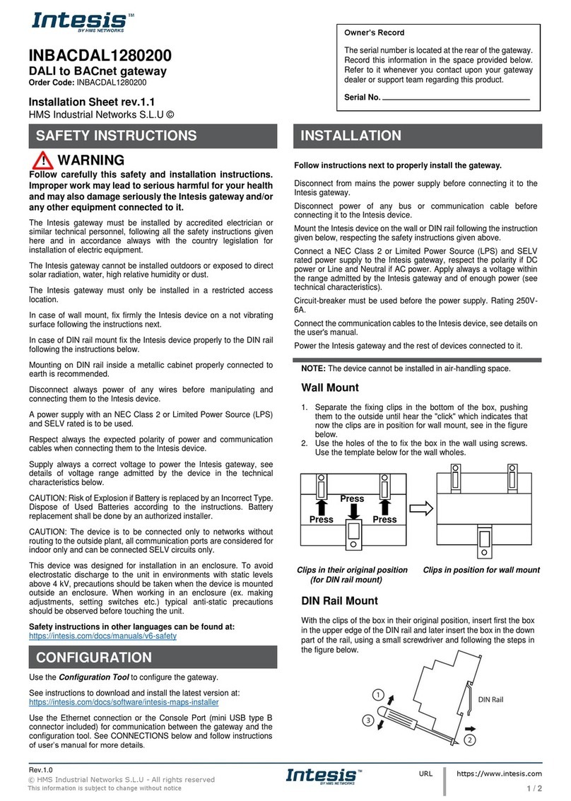
HMS Intesis INBACDAL1280200 Assembly instructions
HMS
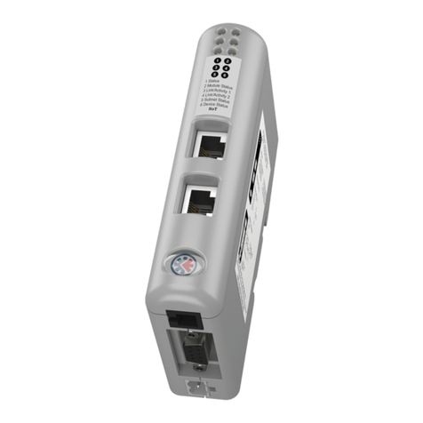
HMS Anybus Communicator IIoT User guide
HMS
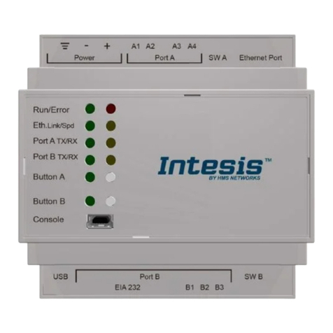
HMS Intesis KNX User manual
HMS
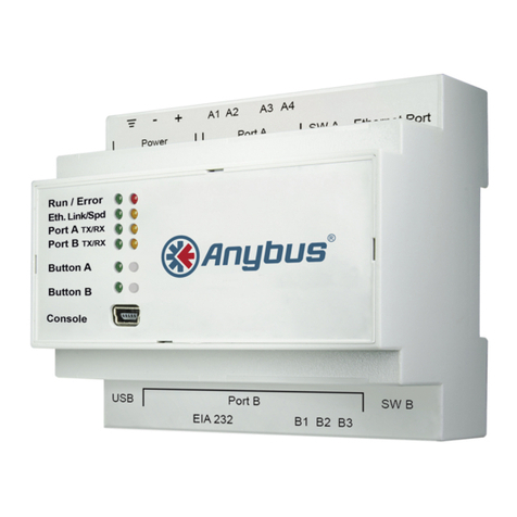
HMS Anybus Modbus to KNX Gateway User manual

HMS
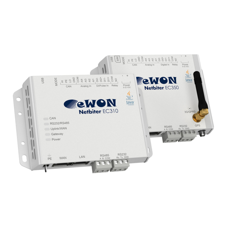
HMS Netbiter EasyConnect User manual
HMS
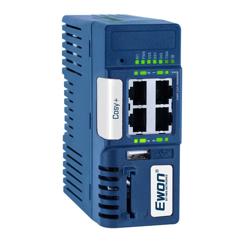
HMS Ewon Cosy+ User manual
HMS
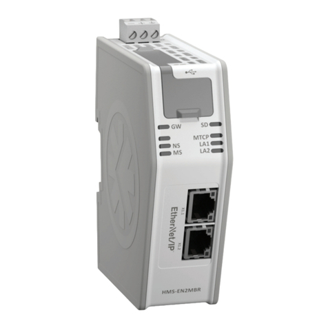
HMS Anybus HMS-EN2MB-R User manual

HMS
HMS Anybus Modbus-TCP/RTU Gateway User manual
HMS
HMS Anybus Edge User manual

HMS
HMS Netbiter EasyConnect EC220 Specification sheet

HMS
HMS AnyBus-X AB7607 User manual
HMS
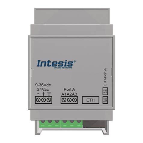
HMS Intesis INMBSOCP 0100 Series Assembly instructions

HMS
HMS Anybus X-gateway CANopen Series User manual

HMS
HMS Anybus Modbus-TCP/RTU Gateway User manual
HMS
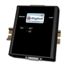
HMS AnyBus-X J1939 User manual
HMS
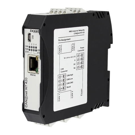
HMS Ixxat CAN@net NT 420 User manual
HMS
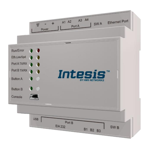
HMS Intesis KNX Series User manual
HMS
HMS Anybus-S Interbus User manual
HMS
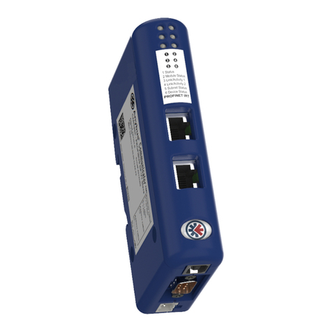
HMS Anybus Communicator CAN PROFINET IRT 2.32 User manual
HMS
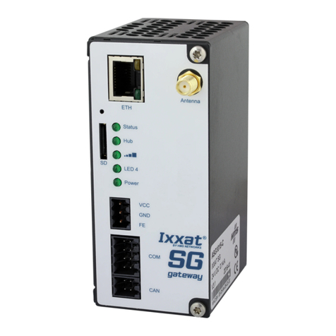
HMS Ixxat SG-gateway User guide
Popular Gateway manuals by other brands

LST
LST M500RFE-AS Specification sheet

Kinnex
Kinnex Media Gateway quick start guide

2N Telekomunikace
2N Telekomunikace 2N StarGate user manual

Mitsubishi Heavy Industries
Mitsubishi Heavy Industries Superlink SC-WBGW256 Original instructions

ZyXEL Communications
ZyXEL Communications ZYWALL2 ET 2WE user guide

Telsey
Telsey CPVA 500 - SIP Technical manual

