manuals.online logo
Brands
  1. Home
  2. •
  3. Brands
  4. •
  5. Solid State Logic
  6. •
  7. Dj Equipment
  8. •
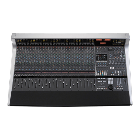
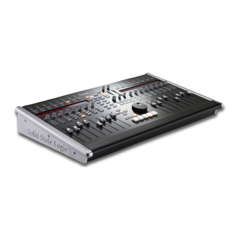
  9. Solid State Logic C200 routing guide User manual

Solid State Logic C200 routing guide User manual

Installation Guide
C200 Insta ation Guide
Solid State Logic
Digital Broadcast Console
Installation Guide
Version 2.0.0
82S6PC2010C
C200 Insta ation Guide
Solid State Logic
S O U N D || V I S I O N
Begbroke, Oxford, England, OX5 1 U • +44 (0)1865 842300
320 West 46th Street, 2nd Floor, New York, NY 10036, USA • +1 (1) 212 315 1111
Suite 401, 5757 Wilshire Blvd, Los Angeles, CA 90036, USA • +1 (1) 323 549 9090
3-55-14 Sendagaya, Shibuya-Ku,Tokyo 151-0051, Japan • +81 (0)3 5474 1144
7 bis, rue de la Victoire, le Blanc Mesnil, Paris 93150, France • +33 (0)1 48 67 84 85
Via Timavo 34, 20124 Milano, Italy • +39 (0)39 2328 094
Visit SSL at U L: http://www.solid-state-logic.com
© Solid State Logic
All ights reserved under International and Pan-American Copyright Conventions
C100, C200, C300, Centuri, C-SB StageBox, NetBridge, NiTech,
Solid State Logic and SSL are trademarks of Solid State Logic
All other product names and trademarks are the property of their respective owners
No part of this publication may be reproduced in any form or
by any means, whether mechanical or electronic, without the
written permission of Solid State Logic, Oxford, England
As research and development is a continual process, Solid State Logic reserves the right
to change the features and specifications described herein without notice or obligation
E&OE
Contents
1 Introduction 2
2 Safety Considerations 3
Safety Warnings 4
CE/ CC/WEEE Certification and Directives 5
3 Pre-Installation Information 6
Services Provided by SSL 6
Physical/Structural 7
Console ootprint and Side Profile 8
Centuri and Stagebox Side View 10
Technical 11
4 System Components 13
Console rame 13
The Centuri Processor 15
The Centuri Processor Cards 16
C-SB Stagebox (option) 21
MORSE (option) 21
NetBridge (option) 23
Script Tray (option) 25
Loudspeaker Shelf (option) 25
XGA Video Switcher 25
5 Installation 27
Connections 27
Earth Connection 27
Console Control 29
PSU Status 31
Sync 31
I/O – MicAmp Card 33
I/O – Analogue Card 33
I/O – Digital Card 35
I/O – MADI Card 35
GPI/O Card 37
C-SB Stagebox Wiring 39
Talkback and Oscillator 43
Phasescope and Meter Wiring 45
Appendices
A Equipment Specifications 47
B Connector Details 51
C Connector Pinouts: Console 53
Processor Crate 56
NetBridge 62
D Audio Interfacing 63
E Environmental Specification 65
Stagebox Installation Requirements 67
G SSL Part Numbers by Description 69
Page 1
Section 1 – Introduction
The object of this manual is to provide purchasers of the C200™ Console and Centuri™ Processor with information in
the following areas:
• Safety considerations
• Installation requirements
• Items supplied: – Main components and optional items
• Installation: – Physical assembly
– Electrical connections and cabling
– System options
• Specifications and Physical dimensions
• Pinouts of standard connectors
The information provided by this manual is relevant to all of the versions of the C200.
The aspects of the C200 which can be customised – frame size, channel layout, meter panel as examples – will be fully
documented in the Custom Specification information for a specific console.
The Custom Specification information, which details the actual console as built, will be found in Section 10 of the console’s
Service Manual.
Page 2
C200 Insta ation Guide
Section2 – Safety Considerations
This section contains definitions and warnings, and practical information to ensure a safe working environment. Please take
time to read this section before undertaking any installation work.
Definitions
‘Maintenance’
All maintenance must be carried out by fully trained personnel.
Note: it is advisable to observe suitable ESD precautions when maintaining electronic assemblies.
‘Non-User Adjustments’
Adjustments or alterations to the equipment may affect the performance such that safety and/or international
compliance standards may no longer be met.Any such adjustments must therefore only be carried out by fully trained
personnel.
‘Users’
This equipment is designed for use solely by engineers and competent operators skilled in the use of professional
audio equipment.
‘Environment’
This product is a class A product intended to form an integrated component part of a professional audio recording,
mixing, TV, radio broadcast or similar studio wherein it will perform to specification providing that it is installed
according to professional practice.
Installation Instructions
Voltage Selection and Fusing
Although the majority of SSL equipment uses auto-ranging power supplies, some sub-systems have user-selectable voltage
inlets. Always confirm that the input mains voltage range is set correctly before applying power. Always isolate the mains
supply before changing the input range setting.
If it is ever necessary to replace a blown mains-fuse, then always use the correct rating and type of replacement. If a
correctly rated fuse continues to blow, then a fault exists and the cause should be investigated or the unit returned to SSL
for repair/replacement as appropriate.
Details of mains settings and correct fuse ratings can be found in Appendix A of this manual.
Electrical Safety Warning
When installing or servicing any item of SSL equipment with power applied, when cover panels are
removed, HAZARDOUS CONDITIONS CAN EXIST.
These hazards include: High voltages
High energy stored in capacitors
High currents available from DC power busses
Hot component surfaces.
Any metal jewellery (watches, bracelets, neck-chains and rings) that could inadvertently come into contact
with uninsulated parts should always be removed before reaching inside powered equipment.
Safety Considerations
Section 2
Page 3
Safety Earth Connection
Any mains powered item of SSL equipment that is supplied with a 3-core mains lead (whether connectorised or not) should
always have the earth wire connected to the mains supply ground.This is the safety earth and grounds the exposed metal
parts of the racks and cases and should not be removed for any reason.
Mains Supply and Phases
SSL equipment is designed for connection to single-phase supplies with the Neutral conductor at earth potential – category
TN – and is fitted with a protective fuse in the Live conductor only. It is not designed for use with Phase (Live) and Neutral
connections reversed or where the Neutral conductor is not at earth potential (TT or IT supplies).
All mains powered assemblies must be connected to the same mains phase. In particular, note that as PSU redundancy is
standard, the two input leads must NOT be connected across different phases.
Mains cables will be coded with either of the following colour schemes:
1or 2
LIVE: Brown Black
NEUTRAL: Blue White
EARTH: Yellow/Green Green
Mains Isolation and Over-Current Protection
An external disconnect device (switch) is required for this equipment which must be installed according to current wiring
regulations. A detachable power cord, if fitted to this equipment, is a suitable disconnect device; otherwise an approved
disconnect switch is required – the rating of which is defined in the product specification (Appendix A) and on the
equipment itself.
An external over-current protection device is required to protect the wiring to this equipment which must be installed
according to the current wiring regulations.The fusing or breaking-current is defined in the product specification. In certain
countries this function is supplied by use of a fused plug.
Some equipment (specifically units with PSU Redundancy) utilises multiple power sources. This is clearly marked on the
equipment.The finished installation must also be clearly marked to ensure that all sources of power are removed before
servicing begins.
Physical Safety
Most subsystems are too heavy for one person to lift.Take particular care when removing the computer chassis from the
equipment rack.
If the console trim is removed for any reason then there may be sharp edges exposed on the frame metalwork.
Page 4
C200 Insta ation Guide
CE Certification
The C200/Centuri system is CE compliant. Note that the majority of cables supplied with SSL equipment are
fitted with ferrite rings at each end.This is to comply with the current regulations and these ferrites should not
be removed.
If any of the console metalwork is modified in any way – particularly the addition of holes for custom switches etc. – this
may the adversely affect the CE certification status of the product.
FCC Certification
The equipment which forms a C200/Centuri system has been tested and found to comply with the limits for a
Class A digital device, pursuant to part 15 of the CC Rules. These limits are designed to provide reasonable
protection against harmful interference when the equipment is operated in a commercial environment.
This equipment generates, uses and can radiate radio frequency energy and, if not installed and used in accordance with
the instruction manual, may cause harmful interference to radio communications. Operation of this equipment in a
residential area is likely to cause harmful interference in which case the user will be required to correct the interference
at his own expense.
Instructions for Disposal of WEEE by Users in the European Union
The symbol shown here, which is on the product or on its packaging, indicates that this product must not
be disposed of with other waste. Instead, it is the user’s responsibility to dispose of their waste equipment
by handing it over to a designated collection point for recycling of waste electrical and electronic
equipment.The separate collection and recycling of your waste equipment at the time of disposal will help
to conserve natural resources and ensure that it is recycled in a manner that protects human health and
the environment. or more information about where you can drop off your waste equipment for recycling,
please contact your local city office, your household waste disposal service or where you purchased the
product.
AAA
AAA
AAA
AAA
AAA
AAA
Safety Considerations
Section 2
Page 5
Section 3 – Pre Installation Information
Physical installation of the console is normally carried out by a specialised transportation company. In some cases this will
have been arranged by the local SSL office, in other cases by the facility.
The cables that run between console and processor can be shipped in advance of the console in a separate kit (the pre-
install kit). These cables should be installed by the facility engineers. Instructions for installing these cables are found on
pages 29 to 31 of this manual.
Note: Cables for the connection of ancillary functions, eters, talkback, oscillator and any custom switches etc. are not
supplied by SSL and will need to be provided by the facility. See pages 43–45 for wiring information.
Before the console is installed all building work should be completed and the environment MUST be clean otherwise the
warranty will be rendered invalid.
Before commissioning can take place the following must be completed:
• Air Conditioning installed, tested, blown-through and working
• Lighting installed and tested
• Cable Trunking installed
• Wall and floor finishes completed
• Power Distribution installed and tested
• Cables installed and tested
• Monitor loudspeakers installed and working
• Other utilities (telephone, water etc.) available
Services provided by SS
Commissioning
All C200 systems include on-site commissioning by an SSL engineer. This is usually expected to take from 2 to 4 days
depending on system size, configuration and options. Large systems, or consoles split for shipment, may require an
additional 1–2 days of commissioning time.
You will be contacted by your local SSL office or agent shortly before delivery to arrange a commissioning date.
Training
Three days of standard operator training are provided with each C200 system. If required, this is scheduled to take place
immediately following the commissioning period and is usually carried out by the commissioning engineer.A further day of
advanced operator training is available at additional cost.
On-site maintenance training is also available at additional cost.This can be either one day for a basic overview or two days
for more advanced training.
Training should be requested at time of order. or all training, we recommend that no more than five persons attend each
session. If the use of an interpreter is necessary the training period may need to be extended (at additional cost). Note
that travel and subsistence costs are not normally included. Please contact SSL’s training department at: support@solid-
state-logic.com.
Warranty
All systems normally include 13 months warranty from date of shipment.This does not include consumable items such as
magnetic media, disks etc. urther details may be found in SSL’s Conditions of Trading (printed on the reverse of all SSL
invoices).
Page 6
C200 Insta ation Guide

Physical Requirements
Console Control Surface
The console control surface can be specified to have from 16 to 96 channels so the size and weight will vary considerably.
A dimensioned footprint drawing for each specific console control surface can be provided by SSL’s Project Engineering
Department. See page 8 for an example of a 32-channel footprint.
Consoles can be built with split points at any profile.The console can then be split for shipment to simplify installation into
client’s premises. Reassembly will be by SSL engineers.
Refer to Appendix A for weights and power consumption information.
Rack Mounting Equipment – Centuri, NetBridge and Stageboxes
The Centuri Processor is a 15U height chassis into which a range of I/O cards can be fitted.The system’s processing and
DSP resource is also housed in the Centuri rack.The Centuri is therefore fitted with cooling fans and is expected to be
housed in a separate ‘machine’ room.
A 19” equipment rack will need to be provided into which the Centuri Processor can be mounted. Note when positioning
the rack that cards are inserted into the Centuri Processor from both the front and the rear depending on function.
Clearance for access to cards must therefore be provided both in front of and behind the rack (see page 10 for service
clearance diagram).
NetBridge – which is an option – is a 2U high rack mounting unit.
Remotely located stageboxes (C-SBs) – which are also optional – may be specified.These are 14U rack units.
Note. Centuri, NetBridge and stagebox units UST be supported on shelves and not only by the rack ears.
SSL can supply 39U 800mm deep equipment racks and shelves if requested (at additional cost). Other rack heights are
available to special order.
Acoustic Isolation
Because of the noise generated by cooling fans the Centuri core should be located in a separate machine room.Adequate
noise isolation should exist between the machine room and control room/recording areas.
Noise figures for individual units are given in Appendix A.
Pre Insta ation Information
Section 3
Page 7
Page 8
C200 Insta ation Guide
736
1083
45
SECTION
CENTRE
SECTION
MONITOR
1 – 8 9 – 16 17 – 24 25 – 32 33 – 40 41 – 48
427 640
1136
334 72155
2835
48 Channel Footprint
Side Profile Showing Service Access
Display
cards
Connector
Panels
Power
supplies
Air Conditioning Requirements
Air conditioning will almost certainly be required for both the Machine and Control rooms in order to maintain the
temperature and humidity to within the required levels.
Power dissipation figures for console control surface and equipment rack are listed in Appendix A.
Appendix E contains the environmental specification for SSL equipment.
Cable Ducting
Cable ducting will be required between the console and the Machine room (as well as to any outboard racks and the
recording areas).The ducting provided should be of sufficient size such that approximately 50mm x 35mm is available for
console surface connection.
The connectors for all control and interface cables are located beneath the console’s Centre Section.The connector panels
are orientated so that cables will route towards the rear of the desk.
The mains input power connector will be located on a separate panel.This panel is usually positioned in a bay adjacent to
the Centre Section nearest to the centre of the console but may vary due to console layout.
Cable sets are available in 10, 16, 20, 25, 48 and 80m standard lengths. Sets longer than 16m are at additional cost.
Service Access
Access to all major electronic assemblies within the frame is either from the front or from beneath the console.The meter
LCD panels are retained by finger-screw fastener beneath the top trim.The top trim is designed to hinge upwards to allow
access to these screws. If the console is being built into restricted space – as in some mobile installations – then always
allow a minimum of 80mm clearance above the top trim.
Sufficient clearance must be provided in front of and behind the rack into which the Centuri processor is installed so that
cards can easily be removed. See the drawing on page 10 for minimum clearances.
Pre Insta ation Information
Section 3
Page 9
Page 10
C200 Insta ation Guide
Centuri Processor Crate (side view) Showing Card Access
C-SB Crate (side view) Showing Card Access
Dimensions in mm
592 270
15U
14U
270
462 270
ront
Rear
ront
Rear
Technical Requirements
Video Sync Source
The Centuri Processor requires a feed of video sync. Other sources – MIDI or wordclock etc. – cannot be used as the
sync reference.
The sync required is 75Ω 1V(pk-pk) black-and-burst video.The standard can be either PAL (625 line, 50Hz) , NTSC (525
line, 59.94Hz or 60Hz). Composite sync may also be used.
Many other studio peripherals (digital recorders, editors and all video picture recorders) will also require a feed of video
sync. Depending on the studio configuration, a suitable video distribution amplifier may also be required.
Note :The Centuri processor does not provide internal sync generation.
Power Connections – Mains Input Voltage & Current
Both the console control surface and the Centuri processor rack are fitted with auto-sensing power supplies and will
function at any voltage from 100 to 240 volts without adjustment.
The console is supplied with one or more detachable mains leads.These leads are 2m in length and the cable diameter is
11mm.The free end of these leads is unterminated for connection to a suitable outlet.
C200 systems can be fitted with dual redundant power supplies for ‘on-air’ use. In this case, the console will be fitted with
two mains input connectors. Consoles larger than 56 channels will be fitted with two input connectors for the standard
mains supply, so if the same console is also fitted with PSU redundancy it will have four input leads.
The inrush current present when powering the console can be significant – typically ten times the steady current – so the
use of ‘slow’ or ‘motor’ rated fuses/circuit-breakers is recommended.
NetBridge (which is a separate 2U unit – see page 23) is fitted with a voltage select switch for 230V or 115V operation.
Confirm that the voltage is correctly set before applying power – see page 23.
See Appendix A for equipment specifications.
Grounding
A standard system should not require any additional grounding over and above that supplied by a correctly installed mains
supply. All rack unit chassis are permanently bonded to mains earth. A permanent mains earth connection via the mains
inlet must be provided.
If, due to the quality of the mains wiring within an installation, it is deemed necessary to improve upon the mains earthing,
chassis ground connection points are provided as follows:
Centuri rack chassis ground can be accessed via a stud located on the rear panel.
Console chassis ground can be accessed via a stud located on the mains power connector panel.
All audio connectors, both analogue and digital, have their screen pins connected directly to the chassis at the point of
entry to comply with AES/EBU grounding and EMC standards.
Pre Insta ation Information
Section 3
Page 11
Page 12
C200 Insta ation Guide
10 •
5 •
0 •
5 •
10 •
20 •
30 •
40 •
50 •
• •
60 •
Protect
reset
layer
enable
o'ride
Remote
sel
0•
-1•
-2•
-3•
-6•
-9•
-12•
-18•
-20•
-30•
-42•
SIG•
10 •
5 •
0 •
5 •
10 •
20 •
30 •
40 •
50 •
• •
60 •
Protect
reset
layer
enable
o'ride
Remote
sel
0•
-1•
-2•
-3•
-6•
-9•
-12•
-18•
-20•
-30•
-42•
SIG•
10 •
5 •
0 •
5 •
10 •
20 •
30 •
40 •
50 •
• •
60 •
Protect
reset
layer
enable
o'ride
Remote
sel
0•
-1•
-2•
-3•
-6•
-9•
-12•
-18•
-20•
-30•
-42•
SIG•
10 •
5 •
0 •
5 •
10 •
20 •
30 •
40 •
50 •
• •
60 •
Protect
reset
layer
enable
o'ride
Remote
sel
0•
-1•
-2•
-3•
-6•
-9•
-12•
-18•
-20•
-30•
-42•
SIG•
10 •
5 •
0 •
5 •
10 •
20 •
30 •
40 •
50 •
• •
60 •
Protect
reset
layer
enable
o'ride
Remote
sel
0•
-1•
-2•
-3•
-6•
-9•
-12•
-18•
-20•
-30•
-42•
SIG•
10 •
5 •
0 •
5 •
10 •
20 •
30 •
40 •
50 •
• •
60 •
Protect
reset
layer
enable
o'ride
Remote
sel
0•
-1•
-2•
-3•
-6•
-9•
-12•
-18•
-20•
-30•
-42•
SIG•
10 •
5 •
0 •
5 •
10 •
20 •
30 •
40 •
50 •
• •
60 •
Protect
reset
layer
enable
o'ride
Remote
sel
0•
-1•
-2•
-3•
-6•
-9•
-12•
-18•
-20•
-30•
-42•
SIG•
10 •
5 •
0 •
5 •
10 •
20 •
30 •
40 •
50 •
• •
60 •
Protect
reset
layer
enable
o'ride
Remote
sel
0•
-1•
-2•
-3•
-6•
-9•
-12•
-18•
-20•
-30•
-42•
SIG•
2/8
1/7
4/10
6/12
5/11
7-12 SF SET
PRE
A/B SET
EFX
∞
PRE
∞
PRE
∞
PRE
∞
PRE
∞
PRE
∞
PRE
AUXES
3/9
2/8
1/7
4/10
6/12
5/11
7-12 SF SET
PRE
A/B SET
EFX
∞
PRE
∞
PRE
∞
PRE
∞
PRE
∞
PRE
∞
PRE
AUXES
3/9
2/8
1/7
4/10
6/12
5/11
7-12 SF SET
PRE
A/B SET
EFX
∞
PRE
∞
PRE
∞
PRE
∞
PRE
∞
PRE
∞
PRE
AUXES
3/9
2/8
1/7
4/10
6/12
5/11
7-12 SF SET
PRE
A/B SET
EFX
∞
PRE
∞
PRE
∞
PRE
∞
PRE
∞
PRE
∞
PRE
AUXES
3/9
2/8
1/7
4/10
6/12
5/11
7-12 SF SET
PRE
A/B SET
EFX
∞
PRE
∞
PRE
∞
PRE
∞
PRE
∞
PRE
∞
PRE
AUXES
3/9
2/8
1/7
4/10
6/12
5/11
7-12 SF SET
PRE
A/B SET
EFX
∞
PRE
∞
PRE
∞
PRE
∞
PRE
∞
PRE
∞
PRE
AUXES
3/9
2/8
1/7
4/10
6/12
5/11
7-12 SF SET
PRE
A/B SET
EFX
∞
PRE
∞
PRE
∞
PRE
∞
PRE
∞
PRE
∞
PRE
AUXES
3/9
2/8
1/7
4/10
6/12
5/11
7-12 SF SET
PRE
A/B SET
EFX
∞
PRE
∞
PRE
∞
PRE
∞
PRE
∞
PRE
∞
PRE
AUXES
3/9
Ø
Q
IN
Q
COPY
Q
LOAD
PRE
INSET
INSERT PROCESS
C
H
A
N
M
O
N
LF
_+
20
200
480
F/Q
GAIN
0
_+
.7
1
2.8
F/Q
GAIN
0
_+
1.5 3
7.5
F/Q
GAIN
0
_+
Q2
410
17
F/Q
GAIN
0
LMF
HMF
HF
EQ
Ø
Q
IN
Q
COPY
Q
LOAD
PRE
INSET
INSERT PROCESS
C
H
A
N
M
O
N
LF
_+
20
200
480
F/Q
GAIN
0
_+
.7
1
2.8
F/Q
GAIN
0
_+
1.5 3
7.5
F/Q
GAIN
0
_+
Q2
410
17
F/Q
GAIN
0
LMF
HMF
HF
EQ
Ø
Q
IN
Q
COPY
Q
LOAD
PRE
INSET
INSERT PROCESS
C
H
A
N
M
O
N
LF
_+
20
200
480
F/Q
GAIN
0
_+
.7
1
2.8
F/Q
GAIN
0
_+
1.5 3
7.5
F/Q
GAIN
0
_+
Q2
410
17
F/Q
GAIN
0
LMF
HMF
HF
EQ
Ø
Q
IN
Q
COPY
Q
LOAD
PRE
INSET
INSERT PROCESS
C
H
A
N
M
O
N
LF
_+
20
200
480
F/Q
GAIN
0
_+
.7
1
2.8
F/Q
GAIN
0
_+
1.5 3
7.5
F/Q
GAIN
0
_+
Q2
410
17
F/Q
GAIN
0
LMF
HMF
HF
EQ
Ø
Q
IN
Q
COPY
Q
LOAD
PRE
INSET
INSERT PROCESS
C
H
A
N
M
O
N
LF
_+
20
200
480
F/Q
GAIN
0
_+
.7
1
2.8
F/Q
GAIN
0
_+
1.5 3
7.5
F/Q
GAIN
0
_+
Q2
410
17
F/Q
GAIN
0
LMF
HMF
HF
EQ
Ø
Q
IN
Q
COPY
Q
LOAD
PRE
INSET
INSERT PROCESS
C
H
A
N
M
O
N
LF
_+
20
200
480
F/Q
GAIN
0
_+
.7
1
2.8
F/Q
GAIN
0
_+
1.5 3
7.5
F/Q
GAIN
0
_+
Q2
410
17
F/Q
GAIN
0
LMF
HMF
HF
EQ
Ø
Q
IN
Q
COPY
Q
LOAD
PRE
INSET
INSERT PROCESS
C
H
A
N
M
O
N
LF
_+
20
200
480
F/Q
GAIN
0
_+
.7
1
2.8
F/Q
GAIN
0
_+
1.5 3
7.5
F/Q
GAIN
0
_+
Q2
410
17
F/Q
GAIN
0
LMF
HMF
HF
EQ
Ø
Q
IN
Q
COPY
Q
LOAD
PRE
INSET
INSERT PROCESS
C
H
A
N
M
O
N
LF
_+
20
200
480
F/Q
GAIN
0
_+
.7
1
2.8
F/Q
GAIN
0
_+
1.5 3
7.5
F/Q
GAIN
0
_+
Q2
410
17
F/Q
GAIN
0
LMF
HMF
HF
EQ
GATE
IN
COPY
HF
SPLIT
MIC
THR
600
20 RLS
LOAD
50
1
ATT 900
-20
0
10
OUT
350 4K 16K20
G
A
T
E
C
O
M
P
R
E
S
S
0105
16
13
10
7
4
1
-60
0
-30
1:1
4:1
•
20:1
RATIO
RANGE
DLY
FILTER
GAIN
DYNAMICS
GATE
IN
COPY
HF
SPLIT
MIC
THR
600
20 RLS
LOAD
50
1
ATT 900
-20
0
10
OUT
350 4K 16K20
G
A
T
E
C
O
M
P
R
E
S
S
01 05
16
13
10
7
4
1
-60
0
-30
1:1
4:1
•
20:1
RATIO
RANGE
DLY
FILTER
GAIN
DYNAMICS
GATE
IN
COPY
HF
SPLIT
MIC
THR
600
20 RLS
LOAD
50
1
ATT 900
-20
0
10
OUT
350 4K 16K20
G
A
T
E
C
O
M
P
R
E
S
S
01 05
16
13
10
7
4
1
-60
0
-30
1:1
4:1
•
20:1
RATIO
RANGE
DLY
FILTER
GAIN
DYNAMICS
GATE
IN
COPY
HF
SPLIT
MIC
THR
600
20 RLS
LOAD
50
1
ATT 900
-20
0
10
OUT
350 4K 16K20
G
A
T
E
C
O
M
P
R
E
S
S
0105
16
13
10
7
4
1
-60
0
-30
1:1
4:1
•
20:1
RATIO
RANGE
DLY
FILTER
GAIN
DYNAMICS
GATE
IN
COPY
HF
SPLIT
MIC
THR
600
20 RLS
LOAD
50
1
ATT 900
-20
0
10
OUT
350 4K 16K20
G
A
T
E
C
O
M
P
R
E
S
S
01 05
16
13
10
7
4
1
-60
0
-30
1:1
4:1
•
20:1
RATIO
RANGE
DLY
FILTER
GAIN
DYNAMICS
GATE
IN
COPY
HF
SPLIT
MIC
THR
600
20 RLS
LOAD
50
1
ATT 900
-20
0
10
OUT
350 4K 16K20
G
A
T
E
C
O
M
P
R
E
S
S
01 05
16
13
10
7
4
1
-60
0
-30
1:1
4:1
•
20:1
RATIO
RANGE
DLY
FILTER
GAIN
DYNAMICS
12345678
123456 78
9 10 11 12 13 14 15 16
17 18 19 20 21 22 23 24
25 26 27 28 29 30 31 32
33 34 35 36 37 38 39 40
41 42 43 44 45 46 47 48
MT Busses
0
2
4
6
8
12
14
16
24
28
SIG
36
52
44
10
18
20
123456
Small Fader
78 9 10 11 12
123456
Large Fader
7 8 9 10 11 12
Mic
12345 678
9 10 11 12 13 14 15 16
17 18 19 20 21 22 23 24
25 26 27 28 29 30 31 32
33 34 35 36 37 38 39 40
41 42 43 44 45 46 47 48
MT Busses
0
2
4
6
8
12
14
16
24
28
SIG
36
52
44
10
18
20
123456
Small Fader
78 9 10 11 12
123456
Large Fader
7 8 9 10 11 12
Mic
12345 67 8
9 10 11 12 13 14 15 16
17 18 19 20 21 22 23 24
25 26 27 28 29 30 31 32
33 34 35 36 37 38 39 40
41 42 43 44 45 46 47 48
MT Busses
0
2
4
6
8
12
14
16
24
28
SIG
36
52
44
10
18
20
123456
Small Fader
78 9 10 11 12
123456
Large Fader
7 8 9 10 11 12
Mic
12345678
9 10 11 12 13 14 15 16
17 18 19 20 21 22 23 24
25 26 27 28 29 30 31 32
33 34 35 36 37 38 39 40
41 42 43 44 45 46 47 48
MT Busses
0
2
4
6
8
12
14
16
24
28
SIG
36
52
44
10
18
20
123456
Small Fader
78 9 10 11 12
123456
Large Fader
7 8 9 10 11 12
Mic
12345678
9 10 11 12 13 14 15 16
17 18 19 20 21 22 23 24
25 26 27 28 29 30 31 32
33 34 35 36 37 38 39 40
41 42 43 44 45 46 47 48
MT Busses
0
2
4
6
8
12
14
16
24
28
SIG
36
52
44
10
18
20
123456
Small Fader
78 9 10 11 12
123456
Large Fader
7 8 9 10 11 12
Mic
123456 7 8
9 10 11 12 13 14 15 16
17 18 19 20 21 22 23 24
25 26 27 28 29 30 31 32
33 34 35 36 37 38 39 40
41 42 43 44 45 46 47 48
MT Busses
0
2
4
6
8
12
14
16
24
28
SIG
36
52
44
10
18
20
123456
Small Fader
78 9 10 11 12
123456
Large Fader
7 8 9 10 11 12
Mic
12345 67 8
9 10 11 12 13 14 15 16
17 18 19 20 21 22 23 24
25 26 27 28 29 30 31 32
33 34 35 36 37 38 39 40
41 42 43 44 45 46 47 48
MT Busses
0
2
4
6
8
12
14
16
24
28
SIG
36
52
44
10
18
20
123456
Small Fader
78 9 10 11 12
123456
Large Fader
7 8 9 10 11 12
Mic
12345678
9 10 11 12 13 14 15 16
17 18 19 20 21 22 23 24
25 26 27 28 29 30 31 32
33 34 35 36 37 38 39 40
41 42 43 44 45 46 47 48
MT Busses
0
2
4
6
8
12
14
16
24
28
SIG
36
52
44
10
18
20
123456
Small Fader
78 9 10 11 12
123456
Large Fader
7 8 9 10 11 12
Mic
SF
PAN
SUB
DIV
SF
ST
SOLO CUT
ST
SF to
MT BUS
LR
LR
MONO
L48V
HPF
Lim
CUT
SOLO
REC
10
5
0
5
10
20
30
40
50
•
P
M
MONO
R
SF
PAN
SUB
DIV
SF
ST
SOLO CUT
ST
SF to
MT BUS
LR
LR
MONO
L48V
HPF
Lim
CUT
SOLO
REC
10
5
0
5
10
20
30
40
50
•
P
M
MONO
R
SF
PAN
SUB
DIV
SF
ST
SOLO CUT
ST
SF to
MT BUS
LR
LR
MONO
L48V
HPF
Lim
CUT
SOLO
REC
10
5
0
5
10
20
30
40
50
•
P
M
MONO
R
SF
PAN
SUB
DIV
SF
ST
SOLO CUT
ST
SF to
MT BUS
LR
LR
MONO
L48V
HPF
Lim
CUT
SOLO
REC
10
5
0
5
10
20
30
40
50
•
P
M
MONO
R
SF
PAN
SUB
DIV
SF
ST
SOLO CUT
ST
SF to
MT BUS
LR
LR
MONO
L48V
HPF
Lim
CUT
SOLO
REC
10
5
0
5
10
20
30
40
50
•
P
M
MONO
R
SF
PAN
SUB
DIV
SF
ST
SOLO CUT
ST
SF to
MT BUS
LR
LR
MONO
L48V
HPF
Lim
CUT
SOLO
REC
10
5
0
5
10
20
30
40
50
•
P
M
MONO
R
SF
PAN
SUB
DIV
SF
ST
SOLO CUT
ST
SF to
MT BUS
LR
LR
MONO
L48V
HPF
Lim
CUT
SOLO
REC
10
5
0
5
10
20
30
40
50
•
P
M
MONO
R
SF
PAN
SUB
DIV
SF
ST
SOLO CUT
ST
SF to
MT BUS
LR
LR
MONO
L48V
HPF
Lim
CUT
SOLO
REC
10
5
0
5
10
20
30
40
50
•
P
M
MONO
R
GROUP TAPE GROUP TAPE GROUP TAPE GROUP TAPE GROUP TAPE GROUP TAPE GROUP TAPE GROUP TAPE
LCD Meter panel
Dynamics Tile
EQ Tile
Aux Tile
Small ader Tile
aders (8 individual units)
C200 Channel Bay ayout
Section 4 – System Components
This section gives an overview of the main units in the system. See Appendix A for specifications and Appendices B and C
for connector details and pinouts.
C200 Console
Each console control surface will consist of one Centre Section and can be specified to have from 16 to 96 channel faders
in groups of 8. (Note: a group of 8 faders and controls and its frame is termed a bay). See page 10 for frame sizes.
Each console channel bay consists of five sections: Main aders, Small aders, Auxes, EQ, Dynamics and the meters. This
layout is not fixed so that, for example, the Aux and EQ positions could be swapped.
Only the faders are removable individually, all other panels (termed tiles) are 8 channels wide.
Note that the number of physical faders fitted does not limit the number of processing channels available; this is determined
by the amount of DSP resource fitted to the processor.
The Centre Section may optionally be specified with a 6 or 8-channel LCD phase-scope and has additional space for
mechanical meters. Alternatively, a range of custom meter configurations is possible; these should be detailed at the time
of order.
The console frame may be specified to have 19” wide sections for script space (known as ‘Producer’s’ tables).These can
be fitted with either a full-depth flat table or a shorter table and either 7U or 14U of equipment racking.
SSL's Project Engineering Department can provide specific console footprint drawings detailing metering options during
the specification process.
‘Mobile’ Centre Section
or installations where width is restricted a narrower, or ‘mobile’, Centre Section may be specified.
In this configuration, the Centre Section will consist of a single eight module-width bay fitted with the master control and
monitoring panels. The section containing the T T display and motion control panel is not fitted. This will reduce the
console overall width by 387mm.
It will be necessary for the facility to provide an external XGA video monitor for the computer control display.
System Components
Section 4
Page 13
Page 14
C200 Insta ation Guide
IN
OUT
WORD
SYNC
IN
OUT
AES
SYNC
MADI
902XD
Tx
Rx
Tx
Rx
LOCK
LOCK
A
B
I
O
I
O
MACHINE
CONTROL
TIME
CODE
CONTROL
SURFACE 1
CONTROL
SURFACE 2
CONTROL
SURFACE 3
9 - 16 1 - 8
25 - 32 17 - 24
9 - 16 1 - 8
25 - 32 17 - 24
AES/EBU IN
AES/EBU OUT
ROUTING CARD
IN OUT1 OUT2 OUT3 OUT4 EXPANSION
THRU
OUT/
960XA
IN OUT
1 - 12
13 - 24
25 - 36
37 - 48
49 - 60
1 - 12
13 - 24
25 - 36
37 - 48
49 - 60
GPI
9 - 16 1 - 8
25 - 32 17 - 24
9 - 16 1 - 8
25 - 32 17 - 24
AES/EBU IN
AES/EBU OUT
A1
A1
ANALOGUE IN
ANALOGUE OUT
A1
A1
ANALOGUE IN
ANALOGUE OUT
+5V
+3V3
IN 1
OUT 1
IN 2
OUT 2
W/CLK
IN 3
OUT 3
IN 4
OUT 4
W/CLK
909XN
Centuri Processor Crate
(Front View)
Centuri Processor Crate
(Rear View)
Access to:
PSUs
Removable media drive
DSP cards
System Disk card
I/O Cards (Mic or Digital)
Access to:
CPU card
ront panel card
GPI/O card
Routing/Link card
I/O Cards (Mic,Analogue or Digital)
NB. Cards shown are an example.
Configuration will vary according to
specification.
+3.3V+5V+5.5V+15V-15V
O
I
+5V
1-6
7-12
SPLIT OUTPUTS
MIC INPUTS
A
SCSI A
SCSI B
SCSI B
+3.3V+5V+5.5V+15V-15V
O
I
+5V
+3V3
FLAG 1
FLAG 12
RESET
Solid State Logic
O X F O R D • E N G L A N D
+5V
+3V3
FLAG 1
FLAG 12
RESET
Solid State Logic
O X F O R D • E N G L A N D
+5V
+3V3
FLAG 1
FLAG 12
RESET
Solid State Logic
O X F O R D • E N G L A N D
+5V
+3V3
FLAG 1
FLAG 12
RESET
Solid State Logic
O X F O R D • E N G L A N D
+5V
1-6
7-12
SPLIT OUTPUTS
MIC INPUTS
A
+5V
1-6
7-12
SPLIT OUTPUTS
MIC INPUTS
A
The Centuri Processor
The Centuri processor is a 15U high 600mm deep rack unit. Cards are fitted to the front and rear of the chassis so space
for access is essential. See page 10 for chassis dimensions and minimum service clearance.
At the front of the processor are located the plug-in PSU units. One unit is capable of powering the system.
The panel below the power supplies is fitted with either a 250Mb Zip drive or an SD memory card reader.This is used to
transfer system software onto the internal hard disk.This panel may also be fitted with the optional MO drive for project
storage.
Below the drives is the front card-cage which has space for 11 plug-in cards, numbered from left to right. The cards are
arranged as follows:
Slots 1–4 Channel DSP cards.
Slot 5 Always fitted with a DSP card for the Centre-Section mixes.
Slot 6 Reserved for future expansion.
Slots 7–10 Can be a combination of additional DSP cards and/or I/O cards – micamp cards (digital or MADI cards to
special order only)†.
Slot 11 Always fitted with the system disc card unless the dual-redundant disc option is specified.
There rear of the processor has space for 12 plug-in cards. Note that these slots are numbered from right to left.
Slots 1–4 Available for I/O cards (analogue, digital and MADI).
Slot 5 Always fitted with the console’s Routing/Link card.
Slot 6 Reserved for the optional GPI/O card.
Slots 7–10 I/O cards – analogue, digital and MADI (mic cards to special order only)†.
Slot 11 Always fitted with the Console-Interface card.
Slot 12 Always fitted with the CPU card.
Note that front and rear mounting I/O cards, although functionally identical, are physically different so it is not possible to
exchange cards between back and front.
† Specifying rear mounted micamp cards or front mounted digital/MADI cards will extend the order lead time.
System Components
Section 4
Page 15
Page 16
C200 Insta ation Guide
ETHERNET
VIDEO 3
VIDEO 2
SYNC
VIDEO 1
SERIAL
+5V
+3V3
FLAG 1
FLAG 12
RESET
Solid State
O X F O R D • E N G L A N D
DSP CARD
SCSI A
SCSI B
SCSI B
DISK CARD
ACHINE
CONTROL
TI E
CODE
CONTROL
SURFACE 1
CONTROL
SURFACE 2
CONTROL
SURFACE 3
+5V
+3V3
IN 1
OUT 1
IN 2
OUT 2
W/CLK
IN 3
OUT 3
IN 4
OUT 4
W/CLK
909XN
System
Disk
Card
CPU
Card
Console
Interface
Card
Routing/ ink
Card
DSP
Card

Other manuals for C200 routing guide

2

Other Solid State Logic Dj Equipment manuals

Solid State Logic C200  routing guide User manual

Solid State Logic

Solid State Logic C200 routing guide User manual

Solid State Logic C100 HDS Technical manual

Solid State Logic

Solid State Logic C100 HDS Technical manual

Solid State Logic AWS 900+ User manual

Solid State Logic

Solid State Logic AWS 900+ User manual

Solid State Logic AWS 900+ SE User manual

Solid State Logic

Solid State Logic AWS 900+ SE User manual

Solid State Logic C100 HDS Technical manual

Solid State Logic

Solid State Logic C100 HDS Technical manual

Solid State Logic SSL UF8 User manual

Solid State Logic

Solid State Logic SSL UF8 User manual

Solid State Logic SSL UF1 User manual

Solid State Logic

Solid State Logic SSL UF1 User manual

Solid State Logic AWS V4 Logictivity User manual

Solid State Logic

Solid State Logic AWS V4 Logictivity User manual

Solid State Logic Duality User manual

Solid State Logic

Solid State Logic Duality User manual

Solid State Logic XLogic Alpha Channel User manual

Solid State Logic

Solid State Logic XLogic Alpha Channel User manual

Solid State Logic Nucleus User manual

Solid State Logic

Solid State Logic Nucleus User manual

Solid State Logic C200  routing guide User manual

Solid State Logic

Solid State Logic C200 routing guide User manual

Solid State Logic Nucleus User manual

Solid State Logic

Solid State Logic Nucleus User manual

Solid State Logic XL-Desk User manual

Solid State Logic

Solid State Logic XL-Desk User manual

Solid State Logic Super-Analogue Outboard XR622 User manual

Solid State Logic

Solid State Logic Super-Analogue Outboard XR622 User manual

Solid State Logic LIVE User manual

Solid State Logic

Solid State Logic LIVE User manual

Popular Dj Equipment manuals by other brands

Chauvet TFX-950CM quick start

Chauvet

Chauvet TFX-950CM quick start

American DJ Inno Color Beam Z7 User instructions

American DJ

American DJ Inno Color Beam Z7 User instructions

Pronomic DX-26 MKII manual

Pronomic

Pronomic DX-26 MKII manual

American DJ Accu Spot 250 Hybrid User instructions

American DJ

American DJ Accu Spot 250 Hybrid User instructions

Eliminator Lighting E 141 OCTO BAR operating instructions

Eliminator Lighting

Eliminator Lighting E 141 OCTO BAR operating instructions

Chauvet Professional EPIX DRIVE 2000 IP user manual

Chauvet Professional

Chauvet Professional EPIX DRIVE 2000 IP user manual

thomann STAIRVILLE Strip Blinder LED RGB WW user manual

thomann

thomann STAIRVILLE Strip Blinder LED RGB WW user manual

JB Systems YETI Operation manuals

JB Systems

JB Systems YETI Operation manuals

Event Lighting PAN2*1*30 user manual

Event Lighting

Event Lighting PAN2*1*30 user manual

American DJ Mega Flash DMX User instructions

American DJ

American DJ Mega Flash DMX User instructions

Eaton FLX S24 user manual

Eaton

Eaton FLX S24 user manual

involight LED MH127B user manual

involight

involight LED MH127B user manual

Midas HD96-24-CC-TP quick start guide

Midas

Midas HD96-24-CC-TP quick start guide

Ibiza LEDBAR24-RC user manual

Ibiza

Ibiza LEDBAR24-RC user manual

U'King ZQ-B345 user manual

U'King

U'King ZQ-B345 user manual

Stage Light PIXBAR HEX 6 user manual

Stage Light

Stage Light PIXBAR HEX 6 user manual

ShowPro LEDMOV640 user manual

ShowPro

ShowPro LEDMOV640 user manual

Kandolite KMLWSH36W10 user manual

Kandolite

Kandolite KMLWSH36W10 user manual

manuals.online logo
manuals.online logoBrands
  • About & Mission
  • Contact us
  • Privacy Policy
  • Terms and Conditions

Copyright 2025 Manuals.Online. All Rights Reserved.