Solid Alliance N2ROU User manual

Confidential & Proprietary 1/28
Alliance_N2ROU (Remote Unit)
User Manual
SOLiD, Inc.
10,9th Floor, SOLiD Space220 Pangyoyeok-ro, Bundang-gu, Seongnam-si, Gyeonggi-do, Korea
393-400
Tel: +82-31-627-6290 Fax: +82-31-627-6209

Confidential & Proprietary 2/28
REVISION HISTORY
Version
Issue Date
Section
Description
V 1.0
September 01, 2018
All
Original
Preface
Technicians using these manuals should have completed the SOLiD Certification Program.
SOLiD also recommends technicians be familiar with the concepts of fiber optic cabling,
networking and wireless communication technologies, and SNMP. We further recommend
training programs offered through CIBET (Certified In Building Engineering Technologist) and
BICSI (Building Industry Consulting Service International).
Copyright
This manual is written and produced by SOLiD and printed in the USA. All rights are reserved
© 2015 SOLiD. Confidential and proprietary. Information contained in this document is company
private to SOLiD and should not be modified, used, copied, reproduced or disclosed in whole or
in part without the written consent of SOLiD.
Technical Support
SOLiD serial numbers must be available to authorize technical support and/or to establish a
return authorization for defective units. The serial numbers are located on the back of the unit,
as well as on the box in which they were delivered. Additional support information may be
obtained by accessing the SOLiD Tehcnology, Inc. website at www.solid.co.kr

Confidential & Proprietary 3/28
Contents
Section1
1.1 Safety & Certification Notice .............................................................................4
Section2
2.1 Overview.........................................................................................................7
2.2 N2ROU ............................................................................................................8
Section3
3.1 Functional Description........................................................................................
3.2 N2ROU Component ..........................................................................................9
3.3 Dimension .....................................................................................................11
Section4
4.1 Installation ....................................................................................................12
4.3 Install N2ROU ................................................................................................12
4.3.1Install N2ROU ................................................................................................12
4.3.2N2ROU Power Cabling ....................................................................................16
4.3.3N2ROU Ground Cabling...................................................................................18
4.3.4Optical Cabling...............................................................................................20
4.3.5Installing AOR (Optional).................................................................................21
Section5
5.1 Specifications.................................................................................................25
5.2 RF Performance..............................................................................................26
5.3 Certification...................................................................................................26

Confidential & Proprietary 4/28
Section1
1.1 Safety & Certification Notice
“Only qualified personnel should handle the DAS equipment. Any person involved in
installation or service of the DAS should understand and follow these safety guidelines.”
- Obey all general and regional safety regulations relating to work on high voltage installations,
as well as regulations covering correct use of tools and personal protective equipment.
- The power supply unit in repeaters contains dangerous voltage level, which can cause electric
shock. Switch the mains off prior to any work in such a repeater. Any local regulations are to
be followed when servicing repeaters.
- To prevent electrical shock, switch the main power supply off prior to working with the DAS
System or Fiber BDA. Never install or use electrical equipment in a wet location or during a
lightning storm.
- When working with units outdoors, make sure to securely fasten the door or cover in an open
position to prevent the door from slamming shut in windy conditions.
- Use this unit only for the purpose specified by the manufacturer. Do not modify or fit any spare
parts that are not sold or recommended by the manufacturer. This could cause fires, electric
shock or other injuries.
- Do not operate this unit on or close to flammable materials, as the unit may reach high
temperatures due to power dissipation.
- Do not use any solvents, chemicals, or cleaning solutions containing alcohol, ammonia, or
abrasives on the DAS equipment. Alcohol may be used to clean fiber optic cabling ends and
connectors.
- Do not look into the ends of any optical fiber or directly into the optical transceiver of any
digital unit. Use an optical spectrum analyzer to verify active fibers. Place a protective cap
over any radiating transceiver or optical fiber connector to avoid the potential of radiation
exposure.
- Allow sufficient fiber length to permit routing without severe bends.
- For pluggable equipment, make sure to install the socket outlet near the equipment so that it
is easily accessible.
- Certification

Confidential & Proprietary 5/28
FCC: This equipment complies with the applicable sections of Title 47 CFR Parts 15,22,24,
27 and 90
UL/CUL: This equipment complies with UL and CUL 1950-1 Standard for safety for
information technology equipment,including electrical business equipment
FDA/CDRH: This equipment uses a Class 1 LASER according to FDA/CDRH Rules.This
product conforms to all applicable standards of 21 CFR Chapter 1, Subchaper J, Part 1040
- A readyily accessible disconnect device shall be incorporated external to the equipment.
- This power of this system shall be supplied through wiring installed in a normal building.
If powered directly from the mains distribution system, it shall be used additional protection,
such as overvoltage protection device
- Only 50 ohm rated antennas, cables and passive equipment shall be used with this remote.
Any equipment attached to this device not meeting this standard may cause degradation and
unwanted signals in the bi-directional system. All components connected to this device must
operate in the frequency range of this device.
- Only 50 ohm rated antennas, cables and passive components operating from 150 - 3 GHz
shall be used with this device.
- The head end unit must always be connected to the Base Station using a direct cabled
connection. Thissystem has not been approved for use with a wireless connection via server
antenna to the base station.
- Round terminals located on the side of a 1 mm2 (16 AWG) or more wires Using permanently
connected to earth. (Green/yellow color)
- Prior to equipment use the service must be registered with the FCC. This can be done through
the FCC’s website at https://signalboosters.fcc.gov/signal-boosters/.

Confidential & Proprietary 6/28
- Access can only be gained by SERVICE PERSONS or by USERS who have been instructed about
the reasons for the restrictions applied to the location and about any precautions that shall be
taken; and
- Access is through the use of a TOOL or lock and key, or other means of security, and is on
trolled by the authority responsible for the location.
- Maximum antenna gain for downlink antenna after accounting for any cable losses should be
less than 2 dBi.
- Notice! Be careful not to touch the Heat-sink part due to high temperature.
-Use of unauthorized antennas, cables, and/or coupling devices not conforming with
ERP/EIRP and/or indoor‐only restrictions is prohibited.
-Home/ personal use are prohibited.
-Signal booster warning label statements.
<FCC>
<IC>
WARNING: This is NOT a CONSUMER device. It is designed for installation by an installer
approved by an ISED licensee. You MUST have an ISED LICENCE or the express consent of an
ISED licensee to operate this device.
CAUTION
DOUBLE POLE/NEUTRAL FUSING

Confidential & Proprietary 7/28
Section2
2.1 Overview
The N2ROU is a coverage system for in-building services delivering voice and data in high quality
and for seamlessly. As a distributed antenna system, it provides analog and digital phone
systems that are served in multiple bands through one antenna.
The system covers general public institutions and private facilities.
Shopping malls
Hotels
Campus areas
Airports
Clinics
Subways
Multi-use stadiums, convention centers, etc.
The system helps improve in-building radio environments in poor condition and make better
poor RSSI and Ec/Io. By providing communication services at every corner of buildings, the
system enables users to make a call at any site of buildings.
The system uses both analog (AMPS) and digital (TDMA, CDMA, WCDMA and LTE) methods.
The N2ROU system supports communication standards and public interface protocols in
worldwide use.
Frequencies: 600MHz, 700MHz , 800M , 1900MHz , 2100MHz , 2300WCS , 2.5TDD ,
2.5TDD_M, etc.
Voice protocols: AMPS,TDMA, CDMA,GSM,IDEN, etc.
Data protocols: EDGE,GPRS,WCDMA,CDMA2000,Paging, LTE etc.

Confidential & Proprietary 8/28
The system is featured with the following:
Flexibility & Scalability
Support fiber-optic ports up to 60
Clustering multiple-buildings (campus) as one coverage
Option structures
Modular frequency upgrade
Multi-Band, Multi Operator
Signals with a plurality of service provider transmit simultaneously
Support multi-operator in a band
Low OPEX / CAPEX
Compact design
Upgradable design
Easy installation and maintenance
2.2 N2ROU
The N2ROU (New 2W Remote Optical Unit) is one of Alliance DAS series, and it supports 2W
output power for each band except 2.5TDD module. For 2.5TDD and 2.5TDD M modules, they
need 1.6W output power. The N2ROU has two types of multiplexers: one for supporting 5-band
and one for 7-band. Based on the required frequency, choose one of them for service.
(5-band Multiuplexer: 600 (RX Only), 700M, 800M, 1900M, 2100M, 2.5TDD)
(7-band Multiuplexer: 600 (RX Only), 700M, 800M, 1900M, 2100M, 2.5TDD, 2300WCS, 600M
(TX Only))
The N2ROU transports signals that multiple operators and multiple technologies are transmitted
simultaneously from BTS to a remote location over the same optical fiber. Furthermore, there is
reserved N2RDU slot to support 600LTE . And N2RDU slot is also can be replaced with the desired
frequency band.

Confidential & Proprietary 9/28
Section3
N2ROU Component
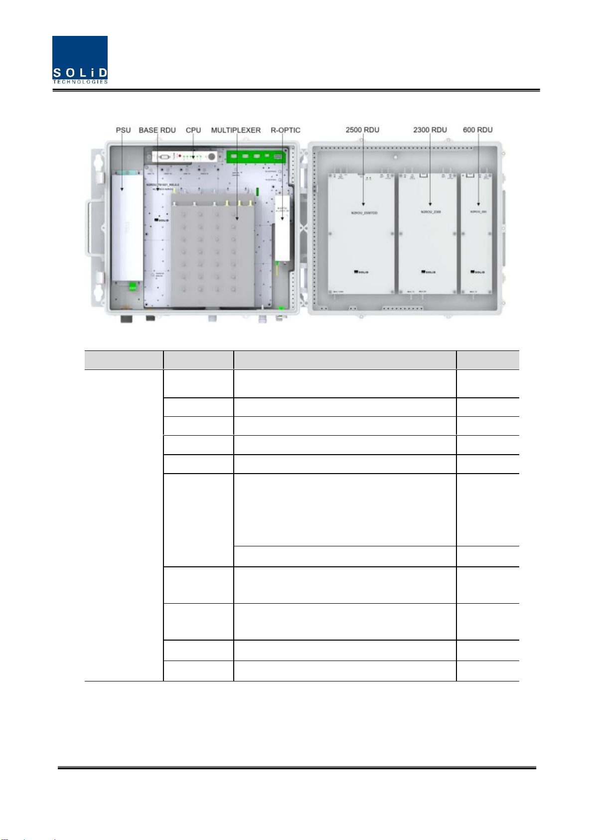
The following figure shows internal configuration of the N2ROU fully equipped with frequency
bands.
Figure 3.5 –Internal View of Remote Unit
The N2ROU receives TX optical signals from Head-End and converts them into RF signals. The
converted RF signals are amplified through High Power Amp in a corresponding RDU, combined
with Multiplexer module and then radiated to the antenna port. RX signals received from the
antenna port are filtered through the multiplexer module, amplified at the RDU modules, and
converted into optical signals via optical module. After converted, the signals are sent to a upper
device of ODU or iODU. Four base bands are installed and additional three RDU modules can be
installed on the right side of the enclosure. Refer to the image above.
Confidential & Proprietary 10/28
The following table describes components of N2ROU.
Unit
Description
N2RDU
Remote Drive Unit
Amplify TX signals
Amplify RX signals
Remove other signals through BPF
RPSU (AC)
Remote AC Power Supply Unit
Input power: 90~280 VAC
Output power: +29.2 VDC
RPSU (DC)
Remote DC Power Supply Unit
Input power: -42 ~ -56 VDC
Output power: +29.2 VDC
R-OPTIC
Remote Optic
Convert RF signals into optical signals and vise versa; Compensate optical loss
Communicate with legacy BIU or iBIU/OEU though the FSK modem
5dBo optical link between ODU (OM4) and ROU
10dBo optical link between ODU (OM1) and ROU
Fiber Connector: SC/APC Connector
Fiber Type: Single Mode Fiber
Optical Wavelength: 1310/1550 WDM
RCPU
Remote Central Processor Unit
Controls signal of each unit
Monitors legacy BIU or iBIU/ODU/OEU through the FSK modem
MUX_5B
Multiplexer 5-band
Combine TX signals from 5 RDUs; Distribute RX signals to 5 RDUs
Allow to use a single antenna port for 5 bands
MUX_7B
Multiplexer 7-band
Combine TX signals from 7 RDUs; Distribute RX signals to 7 RDUs
Confidential & Proprietary 11/28
Allow to use a single antenna port for 7 bands
ROU Enclosure
Enclosure to satisfy IP66
Vertical Mount
Wall Mount
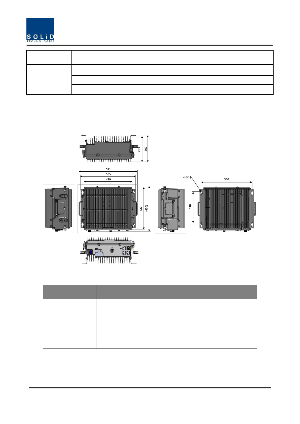
3.1 Dimension
Figure 3.6 –Remote Unit Dimension
ITEM
SPECIFICATION
REMARK
Dimensions (WxHxD)
18.5”x16.5" (10 RU) x 10.2”
(470mm x 420mm x 260mm)
Including Bracket
Weight
Max. 73 lbs (33kg) for base model, 4 bands
Max. 86 lbs (39kg) for 7 bands
MUX included
Confidential & Proprietary 12/28
Section4
4.1 Installation
This chapter describes how to install each unit and optical cables. It also explains how to install
shelves or enclosuers of each unit, power cabling method and optical cabling and RF interface.
Required accessories and tools for installation are list up in the below table.
4.2 Install N2ROU
4.2.1 Install N2ROU
The N2ROU uses a unibody enclosure that is NEMA 4 (IP66) certified to withstand water and
dust intrusion. It can be mounted on a pole, wall, or rack. Basically wall-mounted bracket for
N2ROU is included.
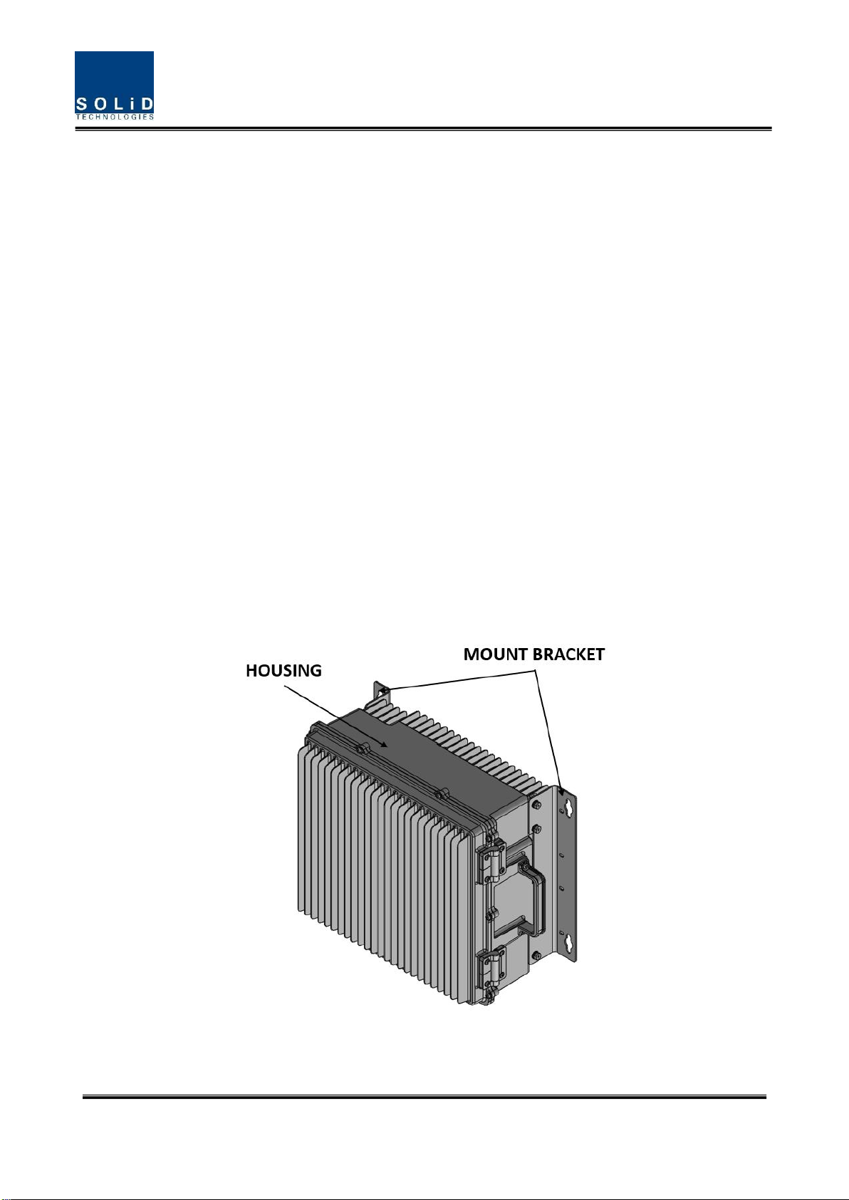
Figure 4.1 –Exterior of N2ROU
Confidential & Proprietary 13/28
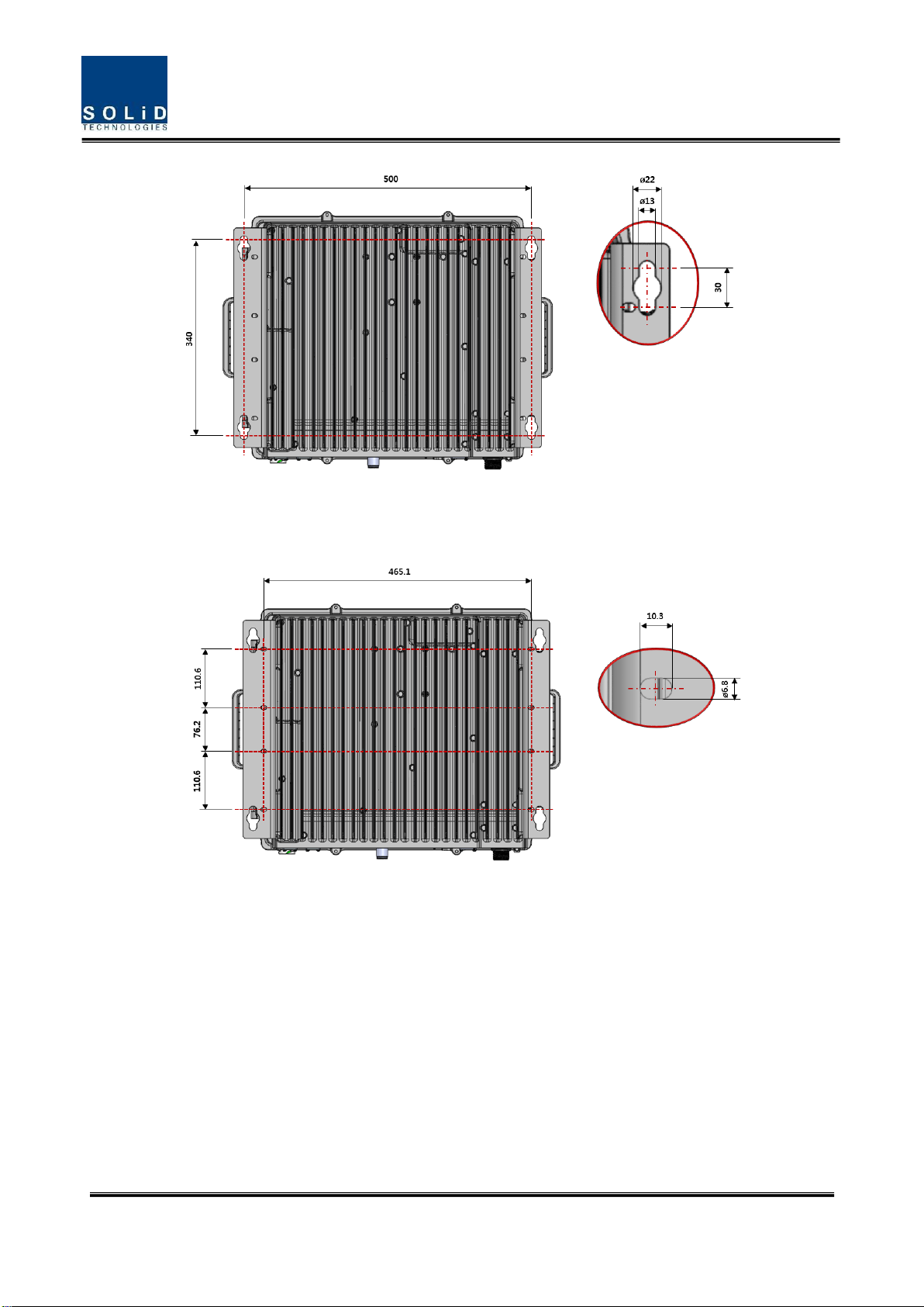
Figure 4.2 –N2ROU Wall Mount Dimensions
Figure 4.3 –N2ROU Rack Mount Dimensions
Confidential & Proprietary 14/28
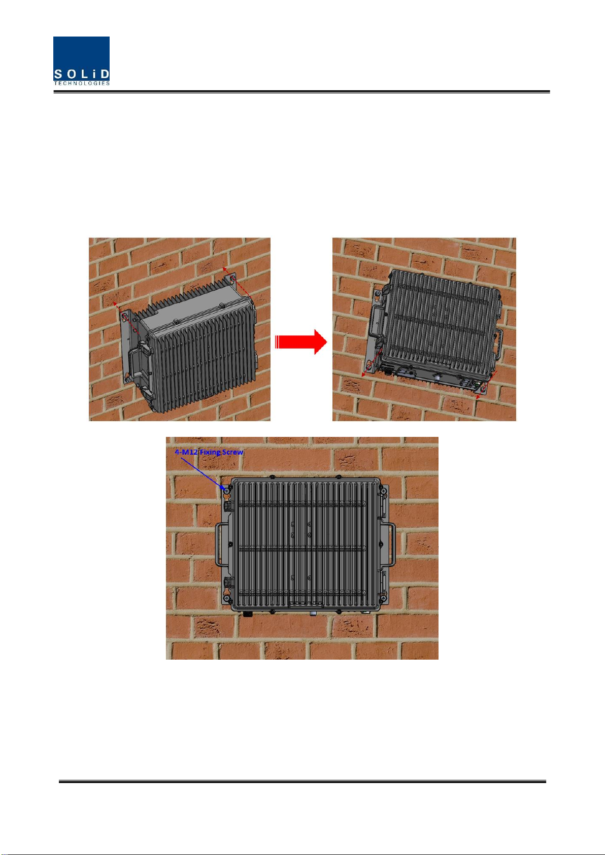
N2ROU Wall Mount Procedure
The enclosure comes with the bracket for wall mounting. It doesn’t need to remove the bracket
to install the enclosure, simply install and tighten 4 mounting bolts to secure the unit. First,
install 2 of M12 mounting bolts roughly half way into the wall. Mount the enclosure and tighten
the bolts. Second, tighten the remaining M12 mounting bolts under the enclosure and secure
the unit tightly.
Figure 4.4 –Installation Procedure
Confidential & Proprietary 15/28
N2ROU Components
N2ROU has the following components:
No.
Unit
Description
Remark
Common Part
Enclosure
N2ROU_BASE_AC or N2ROU_BASE_DC
1EA
RCPU
Remote Central Processor Unit
1EA
R_OPTIC
Remote Optic (only Remote Unit)
1EA
RPSU
Remote AC or DC Power Supply Unit
1EA
Power Cable
MS Connector with 4 holes
1EA
N2RDU
N2RDU_781921
N2RDU_2300
N2RDU_2500TDD
N2RDU_600
ANT1
N2RDU_2500TDD_M
ANT2
MUX_5B
Internal Combiner Unit for 600RX+700, 800+850,
1900, 2100, and 2500
1EA
MUX_7B
Internal Combiner unit for 600+700, 800+850, 1900,
2100, 2500, 2300, and 600TX
1EA
DUP Kit
2500TDD_DUP Kit
BPF Kit
2500TDD_BPF Kit
Basically, the N2ROU is equipped with RCPU to check and control state of each module, R_OPTIC
to covert RF to opticals and vise versa, RPSU to supply power for N2ROU. It should have a power
cable for external rectifier or to supply required power.
Confidential & Proprietary 16/28
4.2.2 N2ROU Power Cabling
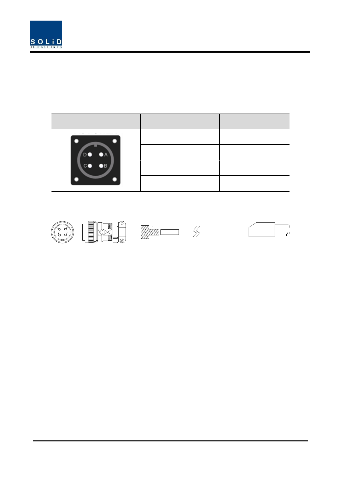
AC Power
The N2ROU supports only AC 120V input power and only a single type of power cable is provided.
The pin discription of AC port is as below. Pay attention to the correct polarity.
AC Power Port
MS Connector No.
Name
Description
A
AC_H
AC Hot
B
AC_N
AC Neutral
C
N.C
Not Connected
D
F.G
Frame Ground
Check if the connection is the same as one seen in the table above and make sure to turn the
power ON. The figure below is the AC power cable that comes with the unit.
Figure 4.5–AC Power Cable
Confidential & Proprietary 17/28
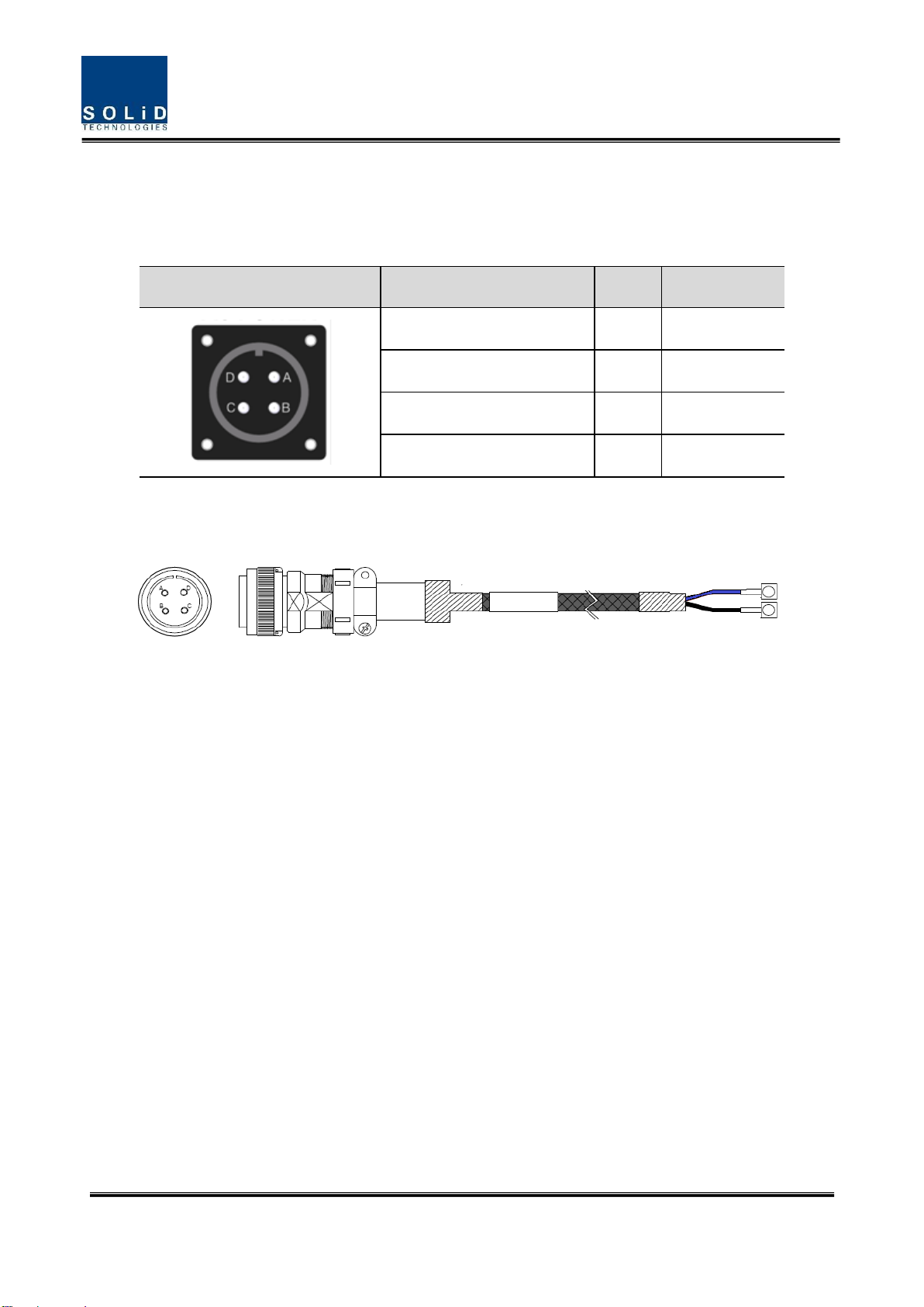
DC Power
The N2ROU supports only DC48V input power and a single type of power cable is provided.
The pin discription of DC port is below. Pay attention to the correct polarity.
DC Power Port
MS Connector No.
Name
Description
A
N.C
Not connected
B
N.C
Not connected
C
+V
+48V
D
-V
-48V
Check if the connection is the same as one seen in the table above and make sure to turn the
power ON. The figure below is the DC power cable included in the package.
Figure 4.6 –DC Power Cable

Confidential & Proprietary 18/28
4.2.3 N2ROU Ground Cabling
The grounding terminal is located at the bottom of N2ROU enclosure fixed by an M6 screw.
Compression terminal is attached already when it is delivered. The recommended thickness of
cable is AWG#6 copper grounding wire.
Figure 4.7 –Location of Ground Terminal
The specification of compression terminal is as follows.
Figure 4.8 –Information of Terminal

Confidential & Proprietary 19/28
The required part number is JOCO 0102-RS06 that supports AWG 6. To install the grounding
cable, follow the steps below.
Figure 4.9 –Installing Ground Terminal
The procedures are
1. Loosen two M6 screws and then take compression terminal off
2. Insert AWG#6 grounding wire into terminal, and then compress a terminal using the
tool
3. Assemble the terminal with 2xM6 screws
4. Cut the ground wire to proper length and connect it to the earth ground source
Confidential & Proprietary 20/28
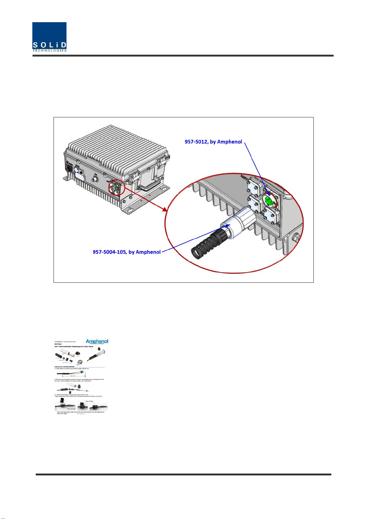
4.2.4 Optical Cabling
The Optical connector is located at the bottom of the N2ROU. Optical cable can be connected
by using its connectors.
Figure 4.10 –Optical Connector
Refer to the figure below for detailed information. The figure is based on LC type, but can be
applied to SC type as well.
Table of contents
Popular Conference System manuals by other brands


Panasonic
Panasonic KX-NS1000 operating manual

AT&T
AT&T MERLIN LEGEND Release 2.0 Analog Multiline... System planning forms

Polycom
Polycom SoundStation 7000 Specifications

Panasonic
Panasonic KX-NS700G Quick reference guide

AT&T
AT&T SPIRIT SPIRIT Attendant owner's manual

Aastra
Aastra 470 installation guide