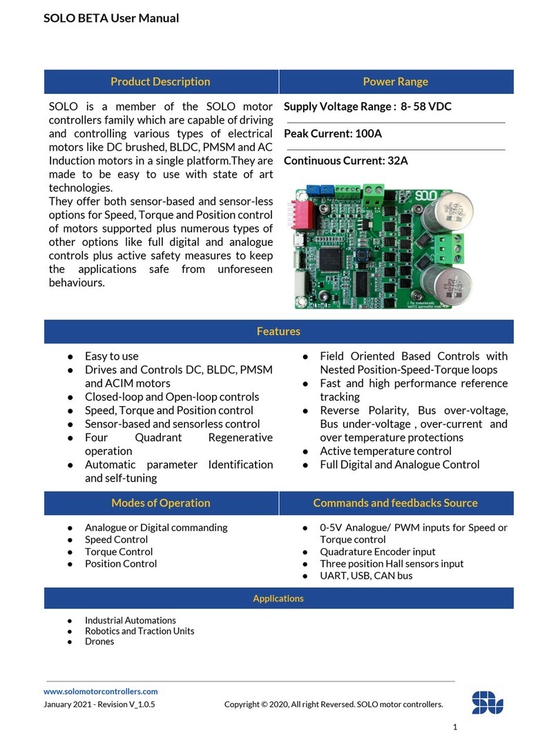
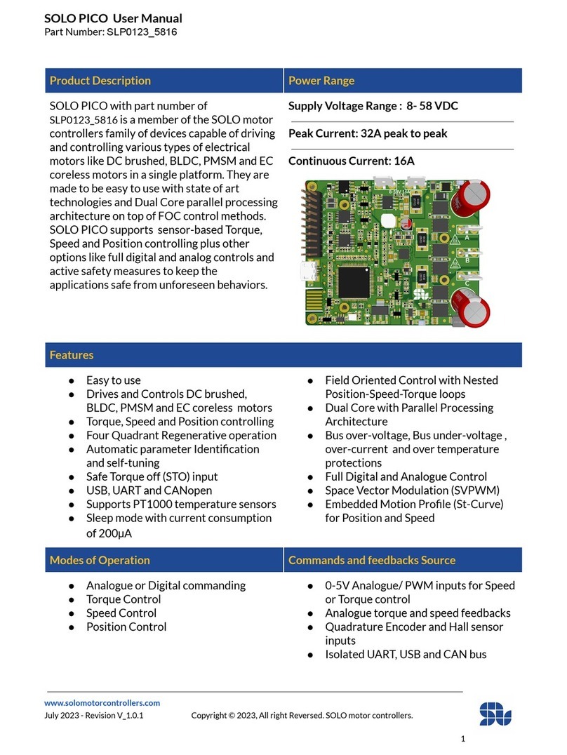
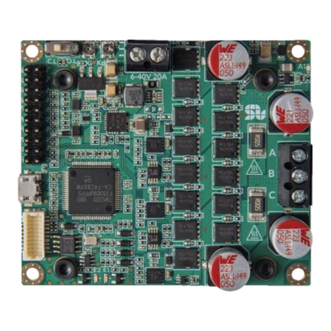
Solo MINI User manual

1
UART and USB User Manual
SOLO UNO
SOLO MINI
SOLO BETA
SOLO Motor Controllers
Firmware versions supported: 0x0000B009 or later

SOLO Communication Manual - UART and USB
www.solomotorcontrollers.com
September 2021 - Revision V_1.0.1 Copyright © 2021, All right Reversed. SOLO motor controllers.
3
Contents:
Purpose of this user manual 7
UART and USB Access points on SOLO UNO: 8
UART and USB Access points on SOLO MINI: 9
UART or USB Hardware Settings: 10
UART/USB Packets formation _ Commanding and Feedbacks: 11
Memory Assignment for Write Commands: 13
DATA Types: 14
UINT32: 14
INT32: 14
Sfxt(32-17): 14
DATA Types Conversions: 15
Converting Sfxt(32-17) data type to floating point data type: 15
Converting float data type to Sfxt(32-17) data type : 16
Converting 32 bits Hex data to signed INT32 format: 17
Converting signed INT32 to 32bits Hex format: 18
WRITE Commands: 19
0x01 : Set Device Address 19
0x02 : Commanding Mode 20
0x03 : Current Limit 21
0x04 : Torque Reference (Iq/IM) 21
0x05 : Speed Reference 22
0x06 : Power Reference 23
0x07 : Motor’s Parameters Identification 23
0x08 : Emergency Stop 23
0x09 : Output PWM Frequency (switching frequency) 24
0x0A : Speed Controller Kp Gain 24
0x0B : Speed Controller Ki Gain 25
0x0C : Motor’s Direction of Rotation 25
0x0D : Motor’s Phase or Armature Resistance 26
0x0E :Motor’s Phase or Armature Inductance 26
0x0F : Motor’s Number of Poles 26

SOLO Communication Manual - UART and USB
www.solomotorcontrollers.com
September 2021 - Revision V_1.0.1 Copyright © 2021, All right Reversed. SOLO motor controllers.
4
0x10 : Incremental Encoder’s Lines 27
0x11 : Speed Limit 27
0x12 : Reset the device address to zero 27
0x13 : Feedback Control Mode 28
0x14 : Reset Factory 28
0x15 : Motor Type 29
0x16 : Control Mode Type 30
0x17 : Current Controller Kp Gain (Torque controller) 30
0x18 : Current Controller Ki Gain (Torque controller) 31
0x19 : Monitoring Modes Enable/Disable 32
0x1A : Magnetizing Current Reference (Id) 33
0x1B : Position Reference 33
0x1C : Position Controller Kp Gain 34
0x1D : Position Controller Ki Gain 34
0x1F : Reset Position to Zero (Home) 34
0x20 : Overwrite the Errors 35
0x21 : Sensorless Observer Gain for Normal BLDC-PMSM Motors 36
0x22 : Sensorless Observer Gain for Ultra-fast BLDC-PMSM Motors 36
0x23 : Sensorless Observer Gain for DC Brushed Motors 37
0x24 : Sensorless Observer Filter Gain for Normal BLDC-PMSM Motors 37
0x25 : Sensorless Observer Filter Gain for Ultra Fast BLDC-PMSM Motors 38
0x26 : UART Baud-Rate 38
0x27 : Encoder or Hall Sensors Calibration Start/Stop 39
0x28 : Per-Unit Encoder or Hall sensor Counter Clockwise offset 39
0x29 : Per-Unit Encoder or Hall sensor Clockwise offset 40
0x2A : Speed Acceleration Value 40
0x2B : Speed Deceleration Value 41
0x2C : CAN Bus Baud Rate 42
Read Commands: 43
0x81 : Device Address 43
0x82 : Phase-A voltage 43
0x83 : Phase-B voltage 43
0x84 : Phase-A Current 44
0x85 : Phase-B Current 44
0x86 : BUS Voltage (Input Supply / Battery) 44
0x87 : DC Motor Current (IM) 45
0x88 : DC Motor Voltage (VM) 45

SOLO Communication Manual - UART and USB
www.solomotorcontrollers.com
September 2021 - Revision V_1.0.1 Copyright © 2021, All right Reversed. SOLO motor controllers.
5
0x89 : Speed Controller Kp Gain 45
0x8A : Speed Controller Ki Gain 46
0x8B : Output PWM Frequency ( Switching Frequency) 46
0x8C : Current Limit 46
0x8D : Quadrature Current (Iq) 47
0x8E : Direct Current / Magnetizing Current (Id) 47
0x8F : Motor’s Number of Poles 47
0x90 : Incremental Encoder’s Lines 48
0x91 : Current Controller Kp Gain 48
0x92 : Current Controller Ki Gain 48
0x93 : Board Temperature 49
0x94 : Motor’s Resistance value 49
0x95 : Motor’s Inductance value 49
0x96 : Speed Feedback 50
0x97 : Motor Type 50
0x99: Feedback Control Mode 51
0x9A : Commanding Mode 51
0x9B : Control Mode Type 52
0x9C : Speed Limit 52
0x9D : PositionController Kp Gain 52
0x9E: Position Controller Ki Gain 53
0xA0 : Position Feedback (Incremental Encoder) 53
0xA1 : Error Register 54
0xA2 : Firmware Version 55
0xA3 : Hardware Version 55
0xA4: Torque Reference (Iq/IM) 55
0xA5 : Speed Reference 56
0xA6 : Magnetizing Current / Id Reference 56
0xA7 : Position Reference 56
0xA8 : Power Reference 57
0xA9 : Desired Direction of Rotation 57
0xAA : Sensorless Observer Gain for Normal BLDC-PMSM Motors 57
0xAB : Sensorless Observer Gain for Ultra-fast BLDC-PMSM Motors 58
0xAC : Sensorless Observer Gain for DC Motor 58
0xAD : Sensorless Observer Filter Gain for Normal BLDC-PMSM Motors 58
0xAE : Sensorless Observer Filter Gain for Ultra Fast BLDC-PMSM Motors 59
0xB0 : Motor’s Angle 59

SOLO Communication Manual - UART and USB
www.solomotorcontrollers.com
September 2021 - Revision V_1.0.1 Copyright © 2021, All right Reversed. SOLO motor controllers.
6
0xB1 : Per-Unit Encoder or Hall sensor Counter Clockwise offset 59
0xB2 : Per-Unit Encoder or Hall sensor Clockwise offset 60
0xB3 : UART Baud Rate 60
0xB4 : Speed Acceleration Value 60
0xB5 : Speed Deceleration Value 61
0xB6 : CAN Bus Baud Rate 61
UART/USB Packet Formation Examples: 62
Change the Direction of Rotation: 63
Stop the Motor [Emergency] 63
Set the Motor’s Number of Poles 63
Change or Set/Reset the Device address: 64
Reset the Device Address to ZERO 64
Set the output switching Frequency (PWM frequency): 65
Reset the Device to Factory Mode: 65
Digital sensorless Torque Control of a BLDC motor. 66
Digital sensorless Speed Control of a Brushless motor. 67
Digital Speed Control of a Brushless motor using Encoders 68
Digital sensorless Speed Control of a DC Brushed motor 69
Digital Speed Control of a DC Brushed motor using Encoder 70
Digital Open-loop Control of a Brushless motor 71
Digital sensorless closed-loop speed Control of an AC Induction Motor 72
Digital Position Control using Quadrature Encoders Examples: 73
Digital Position Control of a Brushless Motor using Encoders: 74
Digital Position Control of a DC Brushed Motor using Encoders: 75

SOLO Communication Manual - UART and USB
www.solomotorcontrollers.com
September 2021 - Revision V_1.0.1 Copyright © 2021, All right Reversed. SOLO motor controllers.
7
Introduction
Purpose of this user manual
This manual intends to discuss the data communication methods of UART and USB with SOLO
UNO, SOLO MINI and SOLO BETA comprehensively.
We will initially start by introduction of major data types which are used for the communications
and then explicitly discuss each of the mentioned protocols, eventually the goal of this Manual is
to give a clear idea about how to setup and utilize SOLO communication networks powered by
UART or USB and what is the purpose of each command existing in our command lists.
If after reading this manual or during your experimentations with our product you had any
questions, you can use SOLO Motor Controllers Forum to share with us the questions and get
back your answers promptly.

SOLO Communication Manual - UART and USB
www.solomotorcontrollers.com
September 2021 - Revision V_1.0.1 Copyright © 2021, All right Reversed. SOLO motor controllers.
8
UART and USB Access points on SOLO UNO:
One of the ways of commanding and getting feedbacks from SOLO UNO is using the USB or
UART communication protocols, the USB is accessible through a micro USB type-B connector
mounted on SOLO UNO and UART is accessible through the “Communication port ” as well as
the “UART/CAN bus Pinout” as can be seen below in Figure 1, by using any of these two
terminals, you can fully control SOLO in a complete digital fashion with all the commands and
feedbacks sent and received through data packets.
Figure 1- UART and USB access points on SOLO UNO
-UART TX is not +5V tolerant on SOLO UNO, as it’s an output pin with signal leveled at
3.3V which is compatible with all Arduino and Raspberry Pi modules, connection of this
pin to +5V rated signals will damage the device.
-UART RX is +5V tolerant and it can be fed with signals both leveled at 3.3V or +5V.
-As can be seen in the communication port, Pins 17 and 19 are the TX and RX pins of UART
respectively and they have the exact same functionality and ratings as UART_RX and UART_TX
pins in “UART/CAN bus Pinout”
-On SOLO BETA models both of the UART_TX and UART_RX pins are 3.3V leveled and they are
not +5V tolerant, to use them with +5V leveled systems proper circuitry (voltage dividers) must be
utilized.

SOLO Communication Manual - UART and USB
www.solomotorcontrollers.com
September 2021 - Revision V_1.0.1 Copyright © 2021, All right Reversed. SOLO motor controllers.
9
UART and USB Access points on SOLO MINI:
SOLO MINI, similar to SOLO UNO offers the exact same connectivity for UART and USB
communications as shown below in Figure 2 both through its “I/O Port” as well as the
“Communication Port”.
Figure 2- UART and USB access points on SOLO MINI
-UART TX is not +5V tolerant on SOLO MINI, as it’s an output pin with signal leveled at
3.3V which is compatible with all Arduino and Raspberry Pi modules, connection of this
pin to +5V rated signals will damage the device.
-UART RX is +5V tolerant and it can be fed with signals both leveled at 3.3V or +5V.
-As can be seen in the communication port, Pins 17 and 19 are the TX and RX pins of UART
respectively and they have the exact same functionality and ratings as UART_RX and UART_TX
pins in “UART/CAN bus Pinout”

SOLO Communication Manual - UART and USB
www.solomotorcontrollers.com
September 2021 - Revision V_1.0.1 Copyright © 2021, All right Reversed. SOLO motor controllers.
10
UART or USB Hardware Settings:
The proper hardware settings to communicate with SOLO are mentioned in table below:
Parameter
Value
Supported baudrates [bits/s]*
937500 or 115200
Number of stop bits
1
Character Length bits
8
Parity Mode
None
-*In Some systems, it might not be possible to use the exact baud-rate of “937500 bits/s”,
in such cases the user can set the baud-rate of the system at “921600 bits/s” and still the
UART or USB communication will be functional and compatible.
-In case of using USB connection, it will be recognized as a “Virtual COM Port (VCP)”, and
the notion of “Baud-rate” will not be relevant as SOLO has a native USB-2
communication and the data-rate is defined by USB-2 ratings, however you can select
any desired baud-rate for this port in VCP mode.
-For Legacy devices it’s possible to put the UART baud-rate on 115200 bits/s, this baud-
rate will cause SOLO to have slightly reduced performance and it’s not recommended if
the best performance of SOLO is required specially for fast Brushless Motors.

SOLO Communication Manual - UART and USB
www.solomotorcontrollers.com
September 2021 - Revision V_1.0.1 Copyright © 2021, All right Reversed. SOLO motor controllers.
11
UART/USB Packets formation _ Commanding and Feedbacks:
To send/receive a command to/from SOLO using UART or USB, you need to form a data packet
combined out of 10 bytes, based on the following format:
INITIATOR
DEVICE ADDRESS
COMMAND
DATA
CRC
ENDING
2 bytes (fixed)
1 byte
1 byte [read/write]
4 bytes [32 bits]
1 byte
1 byte(fixed)
0xFFFF
Variable[0-0xFF]
variable[0-0xFF]
Variable
Variable
0xFE
A complete data packet to be sent/received to/from SOLO is divided into 6 different sections
and each of these sections are as below:
●INITIATOR: This is a constant valued two byte which indicates the start of a packet, the
value is fixed at “0xFFFF '' in Hex format or “65535” in decimal format.
●DEVICE ADDRESS: This is a single byte which stands for the address of the device, each
SOLO can have an address from 0 to 254 and this address will reside in non-volatile
memory and will be remembered after power recycle, this device addressing is useful
when you want to put lots of SOLO’s in a network, so each of them can be assigned to a
unique address. The default value of the address is set at zero.
●COMMAND: This is a single byte, which is a fixed code that defines the type of the
commands/feedbacks that are sent/received to/from SOLO.
●DATA: This is a 4 bytes data, and it’s used for sending/receiving the data part of a
command/feedback, each DATA can have a different type from Uint32, Int32 or Fixed-
Point which are explained later in this manual.
CRC: This is the CRC byte to control the integrity of the data sent through UART, this
functionality is inactive at the moment (it’s filled with zero)
●ENDING: Similar to the packet initiator, this is again a constant single byte valued at
“0xFE” in HEX format, which stands for the end of a packet sent or received.

SOLO Communication Manual - UART and USB
www.solomotorcontrollers.com
September 2021 - Revision V_1.0.1 Copyright © 2021, All right Reversed. SOLO motor controllers.
12
After sending a full packet to SOLO, three scenarios will happen:
1. If the packet is correctly formed and acceptable, SOLO will echo-back the exact same
packet that it received as a sign of acknowledgement of a correct receipt and settings.
2. If the packet is correctly formed, but the value inside the “DATA” part is out of range or
the “COMMAND” is not existing or valid , SOLO will send back the following packets for
each condition which is an indication of an Error in the packet sent.
Packet Error Format for DATA out of range:
0xFFFF
Device Address
Command sent
0xEEEEEEEE
Variable
0xFE
Packet Error Format for non existing Command code:
0xFFFF
Device Address
Command sent
0xAEEEEEEE
Variable
0xFE
3. If the packet is wrongly formed in terms of bytes, initiators and endings, there will be no
response coming back from SOLO, until you send a correct packet.
To communicate with SOLO, there are two types of commands:
1. Commands to Write or Set something, these commands as their name suggests, will allow
the user to tune a parameter inside of SOLO or set a value for the controllers like the
desired speed or torque and so on, beside putting the right COMMAND code, the DATA
section is used to write the desired value in desired register in SOLO.
2. Commands to Read a value from SOLO, using these types of commands, you’ll be able to
read various types of parameters and feedback from SOLO, in real-time or in Monitoring
Mode which will be explained later in this chapter, in these types of commands the DATA
section is mostly filled with ZEROs unless specified.

SOLO Communication Manual - UART and USB
www.solomotorcontrollers.com
September 2021 - Revision V_1.0.1 Copyright © 2021, All right Reversed. SOLO motor controllers.
13
Memory Assignment for Write Commands:
Once a parameter is written into SOLO, depending on the nature of the command two scenarios
for storing the value will occur, either it will be stored on volatile memory of SOLO and resets to
default after power recycling or it will be saved on non-volatile memory of SOLO and
remembered after even power recycling and forever until it’s being overwritten or changed.
1. Volatile parameters: They are shown with “V” inside the Storage section of the
writing table, and they are the parameters that you should write in them
whenever you want to change them or after power recycling ( turn ON/OFF),
they will not be stored in a long-term memory and after a power reset they will be
forgotten and set back to their default value.
2. Memory stored Parameters: These parameters are shown with “M” inside their
storage section of the writing table, after writing in them, their values will be
stored in a non-volatile memory and they will be remembered after power
recycling, The memory used to store these values is a precious resource and the
number of Writings are limited to a couple of Milion times ( 1,000,000 times
guaranteed). So for these types of values which are basically one-time settings for
a long period ( as long as the Motor is the same ), the users should avoid writing in
them everytime if their value has not been changed with respect to the past.

SOLO Communication Manual - UART and USB
www.solomotorcontrollers.com
September 2021 - Revision V_1.0.1 Copyright © 2021, All right Reversed. SOLO motor controllers.
14
DATA Types:
The data types in SOLO are categorized into three main types as shown in table below:
Name
Value
Size[bits]
Range
Resolution
UINT32
Unsigned
Integer
32
[0 to 4,294,967,295]
+/- 1
INT32
Signed Integer
32
[-2,147,483,647 to
2,147,483,647]
+/- 1
Sfxt(32-17)
Fixed Point
32
[-16,384.000 to 16,384.000]
+/- 0.00000762
UINT32:
This data type is used for Unsigned Integer values and it occupies 32 bits.
INT32:
This data type is used for Signed Integer values and it occupies 32 bits.
Sfxt(32-17):
This data type is used to represent the variables with floating point and it occupies 32 bits.
To send and receive commands or feedback properly during communication with SOLO, you
need to convert your data into one of these forms based on the command or feedback that you
are using, as each command has a specific data type.
In all of these formats, the data section occupies 32 bits or 4 bytes, below you can see how one
can convert these data types to tangible numbers from Hexadecimal format that is the default
way of sending or receiving data with SOLO, in this manual the Hexadecimal numbers are either
shown with “0x” in the beginning of the number or “h” at the end of the number.

SOLO Communication Manual - UART and USB
www.solomotorcontrollers.com
September 2021 - Revision V_1.0.1 Copyright © 2021, All right Reversed. SOLO motor controllers.
15
DATA Types Conversions:
Converting Sfxt(32-17) data type to floating point data type:
If the DATA section of a packet received from SOLO, contains a number in Fixed-Point format,
you can use the following two methods to convert it back to a floating point data type depending
on the sign of the received data and whether if it’s a positive value or a negative value:
Condition1) If the data read from SOLO is less than or equal to 0x7FFE0000 (Hex) or
2,147,352,576 (decimal), This means the data is positive, so follow the following steps
1) Convert the hex data read from SOLO into Decimal format
2) The float number = data read from SOLO (in Decimal format) / 131072
Condition2) If the data read from SOLO is greater than 0x7FFE0000 (Hex) or 2147352576
(decimal), This means the data is negative, so the conversion will be as :
1) Subtract the data from 0xFFFFFFFF and then add a 0x1 to it (add 1 to it)
2) Convert the result of step “1” into Decimal format
3) The float number = (data in Decimal format taken from step “2” /131072 ) * -1
Example1 _ positive Numbers:
Data read from SOLO is “0x00030000”
So it’s a Positive Numbers Conversion since the data read from SOLO is less than or equal to
0x7FFE0000 so the conversion will be:
1) Decimal (0x00030000) = 196608
2) 196608 / (131072) = 1.5
Example2 _ negative Numbers:
Data read from SOLO is “0xFFFCCDD2”
So it’s a Negative Numbers Conversion since the data read from SOLO is greater than
0x7FFE0000, so the conversion will be:
1) (0xFFFFFFFF –0xFFFCCDD2 ) + 0x1 = 0x0003322E
2) Decimal ( 0x0003322E ) = 209454
3) (209454 / (131072) )* -1 = -1.598

SOLO Communication Manual - UART and USB
www.solomotorcontrollers.com
September 2021 - Revision V_1.0.1 Copyright © 2021, All right Reversed. SOLO motor controllers.
16
Converting float data type to Sfxt(32-17) data type :
If the DATA section of a packet to be sent to SOLO, contains a number in Fixed-Point format,
you can use the following two methods to convert your real world float number into a Sfxt(32-
17) data type depending on the sign of the float data and whether if it’s a positive value or a
negative value:
Condition1) If the float number is Positive:
1- Multiply the float number into 131072
2- Round down the result into the nearest integer value
3- convert this value to HEX
Condition2) If the float number is Negative:
1- Multiply the float number into 131072
2- Round down the result into the nearest integer value
3- Ignore the sign of the integer and convert this value to HEX (compute the Absolute value)
4- Subtract data from "0xFFFFFFFF"
Example 1_ positive float number:
Data to be sent : 4.2
Conversion:
1) 4.2 * 2^17 = 550,502.4
2) Round(550502.4) = 550502
3) Hex (550502) = 0x0086666
Example 2_ negative float number:
Data to be sent : -14.36
Conversion:
1) -14.36 * 2^17 = -1,882,193.92
2) Round(-1,882,193.92) = -1,882,193
3) Hex (abs (-1,882,193) )= 0x 001CB851
4) 0xFFFFFFFF - 0x001CB851 = 0xFFE3 47AE

SOLO Communication Manual - UART and USB
www.solomotorcontrollers.com
September 2021 - Revision V_1.0.1 Copyright © 2021, All right Reversed. SOLO motor controllers.
17
Converting 32 bits Hex data to signed INT32 format:
If you want to convert a DATA part of a packet read from SOLO into the real world Int32 format,
based on the sign of the DATA you will fact the following two conditions for the conversion:
Condition1) If the data read from SOLO is less than or equal to 0x7FFFFFFF(Hex) or
2147483647 (decimal), This means the data is positive
When the data is positive, we can treat it like a normal unsigned value, so you can just directly
convert the Hex value to decimal with known methods.
Condition2) If the data read from SOLO is greater than 0x7FFFFFFF(Hex) or
2147483647(decimal), This means the data is negative, so the conversion will be as :
1) Subtract the data from 0xFFFFFFFF and then add a 0x1 to it (add 1 to it)
2) Convert the result of step “1” into Decimal format
3) Multiply the result of step 3 to “-1”
Example 1_ positive Numbers:
Data read from SOLO is “0x0003F393”
-The data is smaller than 0x7FFFFFFF so it becomes : Dec (0x0003F393) = +258963
Example 2_ negative Numbers:
Data read from SOLO is “0xFFFCA8AD”
-The data is bigger than 0x7FFFFFFF so we will have:
1. (0xFFFFFFFF - 0xFFFCA8AD ) + 1 = 0x00035753
2. Dec(0x00035753) = 218963
3. 218963 * -1 = -218963

SOLO Communication Manual - UART and USB
www.solomotorcontrollers.com
September 2021 - Revision V_1.0.1 Copyright © 2021, All right Reversed. SOLO motor controllers.
18
Converting signed INT32 to 32bits Hex format:
If you want to convert an INT32 value to a Hex formatted number to place in the DATA part of a
packet to send to SOLO, based on the sign of the data you want to send, you will face the
following two conditions for the conversion:
Condition1) If the data is positive:
If the number you want to send is positive, the only thing you need to do is converting the
integer into HEX like an unsigned value
Condition1) If the data is Negative:
For sending negative Integers with Hex format to SOLO, you need to follow the following steps:
1. Subtract the absolute value of your number from 4294967295(Decimal) or
0xFFFFFFFF(Hex)
2. Add 1 to the result of step 1
3. Convert the result of 2nd step to Hex
Example 1_ positive Numbers:
Data to be sent: 1536
-Hex (1536) = 0x00000600
Example 2_ negative Numbers:
Data to be sent: -56329
-Hex (4294967295 - Abs (-56329) + 1 ) = 0xFFFF23F7

SOLO Communication Manual - UART and USB
www.solomotorcontrollers.com
September 2021 - Revision V_1.0.1 Copyright © 2021, All right Reversed. SOLO motor controllers.
19
WRITE Commands:
Below all the existing Write commands to set a value in SOLO with their description for UART or
USB communication for are listed.
0x01 : Set Device Address
Code: 0x01
Set Device Address
Data Type
Data Range
Units
Memory Storage
Default Value
Uint32
[0-254]
N/A
M
0
Description:
This command sets the desired device address for a SOLO unit; the address can be used to
network multiple SOLO’s in a single network if the address assigned to each unit is unique.

SOLO Communication Manual - UART and USB
www.solomotorcontrollers.com
September 2021 - Revision V_1.0.1 Copyright © 2021, All right Reversed. SOLO motor controllers.
20
0x02 : Commanding Mode
Code: 0x02
Commanding Mode
Data Type
Data Range
Units
Memory Storage
Default Value
Uint32
0 or 1
N/A
V
0
Description:
This command sets the mode of the operation of SOLO in terms of operating in Analogue
mode or Digital Mode based on the value of DATA in the packet with command code of 0x02
as below:
DATA
Actions
0 (0x00000000)
Puts SOLO in Analogue Mode
1 (0x00000001)
Puts SOLO in Digital Mode
Once in Analogue Mode some configuration can be done only at hardware level, as the table below suggests, everything else
outside of the below table can be set only through sending data packets to SOLO through UART, USB or CAN bus.
Action
In Analogue Mode
In Digital Mode
Open-Loop or Closed-Loop Operation
Through PIN 5 of Piano Switch in SOLO
UNO
Through Control Mode Switch on SOLO
MINI
Through PIN 5 of Piano Switch in SOLO UNO
Through Control Mode Switch on SOLO MINI
Motor Type selection
Through PIN 1 and 2 of Piano Switch in
SOLO UNO
Through M1 and M2 Pins on SOLO MINI
Set with command code 0x15
Control Mode selection (Torque, Speed,
Position)
Through PIN 4 of Piano Switch (only
Torque and Speed) in SOLO UNO
Through FN Pin on SOLO MINI
Set with command code 0x16 (Torque, Speed,
Position)
DFU mode
Through PIN 3 of Piano Switch in SOLO
UNO
Through DF Pin on SOLO MINI
Through PIN3 of Piano Switchin SOLO UNO
Through DF Pin on SOLO MINI
Current (Torque) controller Kp and Ki
Gains in closed-loop mode
Auto-tuned after Motor Identification
Set with Command codes of 0x17 and 0x18
(Auto-tuned after Motor Identification)
Speed controller Kp and Ki Gains in
closed-loop Speed mode
Through two physical potentiometers of
Kp and Ki on the board
Set with command codes of 0x0A and 0x0B
respectively
Speed Reference
Sent by PWM or Analogue voltages
through S/T input on Analogue Input port
Set with command code of 0x05
Torque Reference
Sent by PWM or Analogue voltages
through S/T input on Analogue Input port
Set with command code of 0x04
Power/ Current Limit / Magnetizing
Current
Sent by PWM or Analogue voltages
through P/F input on Analogue Input port
Set with command codes of 0x06, 0x03 and
0x1A respectively
This manual suits for next models
2
Table of contents
Other Solo Controllers manuals
Popular Controllers manuals by other brands

Honeywell
Honeywell Aquastat L4007 Product data

American
American PERC-RITE ASD15 Series manual

Horizont
Horizont Hotshock A300 instruction manual

MicroNova
MicroNova Agua-IoT NAVEL 2.0 user guide

Victron energy
Victron energy BlueSolar PWM-Pro Series manual

Full Gauge
Full Gauge MT-530 Super quick start guide