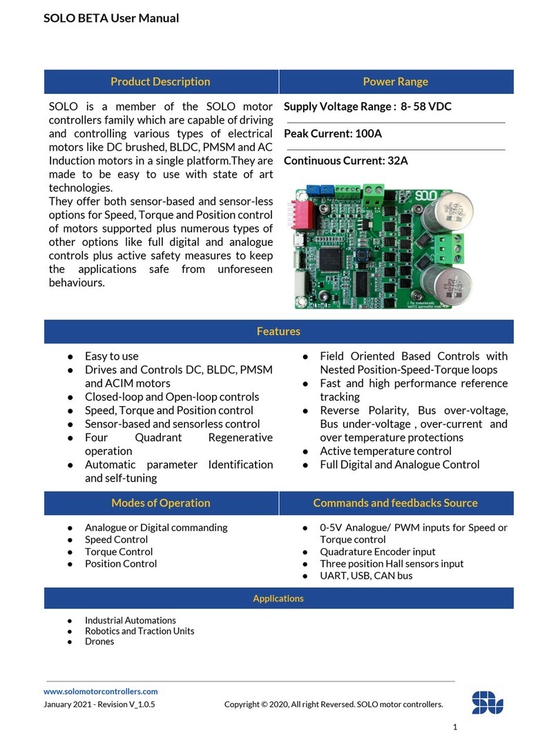
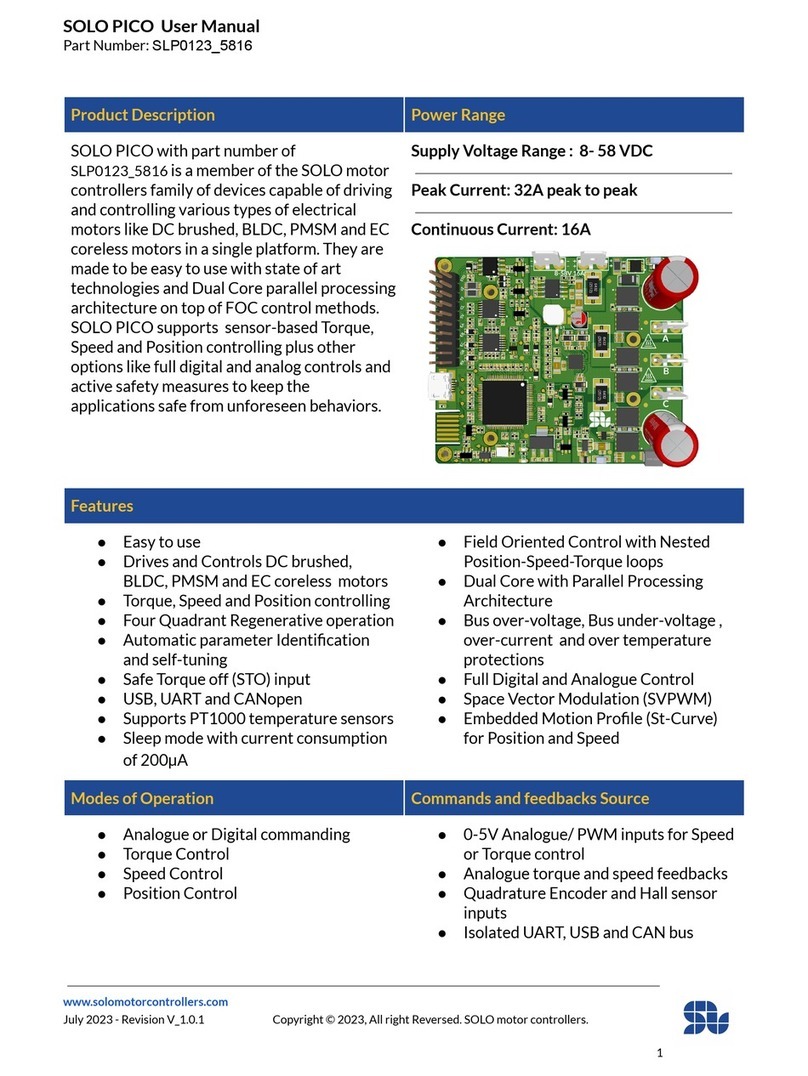
Solo MINI_v2 User manual

SOLO MINI_v2 User Manual
Part Number: SLM0322_4020
www.solomotorcontrollers.com
May 2022 - Revision V_1.0.1 Copyright © 2022, All right Reversed. SOLO motor controllers.
1
Product Description
Power Range
SOLO MINI_v2 with part number of
SLM0322_4020 is a member of the SOLO
motor controllers family of devices capable of
driving and controlling various types of
electrical motors like DC brushed, BLDC,
PMSM, AC Induction and EC coreless motors
in a single platform. They are made to be easy
to use with state of art technologies and Dual
Core parallel processing architecture on top of
FOC control methods. They offer both
sensor-based and sensor-less options for
Speed, Torque and Position controlling of
motors supported plus numerous types of
other options like full digital and Analogue
controls and active safety measures to keep
the applications safe from unforeseen
behaviors.
Supply Voltage Range : 6- 40 VDC
Peak Current: 80A
Continuous Current: 20A
Features
●Easy to use
●Drives and Controls DC, BLDC, PMSM EC
coreless and ACIM motors
●Closed-loop and Open-loop controls
●Speed, Torque and Position control
●Sensor-based and sensorless control
●Four Quadrant Regenerative operation
●Automatic parameter Identification and self-
tuning
●Field Oriented Based Controls with Nested
Position-Speed-Torque loops
●Dual Core with Parallel Processing Architecture
●Reverse Polarity, Bus over-voltage, Bus under-
voltage , over-current and over temperature
protections
●Active temperature control
●Full Digital and Analogue Control
Modes of Operation
Commands and feedbacks Source
●Analogue or Digital commanding
●Speed Control
●Torque Control
●Position Control
●0-5V Analogue/ PWM inputs for Speed or
Torque control
●Quadrature Encoder input (RS422)
●Hall sensors input
●UART, USB, CANopen
Applications
●Industrial Automations
●Robotics and Traction Units
●Drones

SOLO MINI_v2 User Manual
Part Number: SLM0322_4020
www.solomotorcontrollers.com
May 2022 - Revision V_1.0.1 Copyright © 2022, All right Reversed. SOLO motor controllers.
2
Revision History:
Revision
Date
Changes
Firmware version
V1.0.0
30/09/2021
-First Release
0x001B009
V1.0.1
12/05/2022
-SOLO MINI_v2 updated
0x00BB00A

SOLO MINI_v2 User Manual
Part Number: SLM0322_4020
www.solomotorcontrollers.com
May 2022 - Revision V_1.0.1 Copyright © 2022, All right Reversed. SOLO motor controllers.
3
Table of Contents
Power Specifications: 5
Control and Timings specifications: 6
Thermal Specifications: 7
Mechanical Specifications: 7
Mechanical Dimensions: 8
Absolute Maximum Voltage Ratings: 9
Overview of the product 10
Functional Block Diagram: 11
Theory of Operation: 12
FOC Control Architecture in SOLO MINI_v2 for 3-phase Motors: 13
Cascade Control Architecture in SOLO MINI_v2 for DC Motors: 14
SOLO’s Interactional Sections: 15
Connectors and Sections: 16
Section 1 - Motor Output 16
Section 2 - Power Up LED 16
Section 3 - Supply Input 17
Section 4 and 5 - Speed Controller Gains 18
Section 6 - Control Mode Switch 19
Section 7 - I/O Port 21
Section 8 - USB Connection 31
Section 9 - Communication Port 32
Section 10 and 11 - Functionality LEDs 34
Analogue versus Digital Control in SOLO MINI_v2 35
Minimum Required Wirings in Analogue Mode: 36
Wiring Legend: 36
BLDC, PMSM Motors _ Sensorless Closed-loop Mode: 37
BLDC, PMSM or ACIM Motors _ Sensorless Open-loop Mode: 38
AC Induction Motors_ Closed_loop Sensorless Mode: 39

SOLO MINI_v2 User Manual
Part Number: SLM0322_4020
www.solomotorcontrollers.com
May 2022 - Revision V_1.0.1 Copyright © 2022, All right Reversed. SOLO motor controllers.
4
DC brushed Motors_ Closed-loop Sensorless Mode: 40
DC brushed Motors_ Open-loop Sensorless Mode: 41
Standalone Wiring Example (No External Modules): 42
Essential Wiring Example (SOLO MINI_v2 + Arduino UNO) 43
Minimum Required Wirings in Digital Mode: 44
USB Interface Wiring 44
UART Interface Wiring 45
CANopen Interface Wiring 46
Wiring with Incremental Encoders: 47
Wiring with HALL Sensors: 48

SOLO MINI_v2 User Manual
Part Number: SLM0322_4020
www.solomotorcontrollers.com
May 2022 - Revision V_1.0.1 Copyright © 2022, All right Reversed. SOLO motor controllers.
5
Power Specifications:
Description
Units
Values
DC Supply Voltage Range (continuous)
VDC
8 to 37
DC Bus Overvoltage Limit
VDC
40
DC Bus Undervoltage Limit
VDC
6*
Maximum Peak Output Current
A
80
Maximum Continuous Output Current
A
20
Maximum Continuous Output Power
W
500
Maximum Peak Output Power
W
800
Internal Bus Capacitance
µF
880
Switching Frequency (output PWM frequency)
kHz
8 to 80
*The minimum recommended voltage for high-current applications is 8V.

SOLO MINI_v2 User Manual
Part Number: SLM0322_4020
www.solomotorcontrollers.com
May 2022 - Revision V_1.0.1 Copyright © 2022, All right Reversed. SOLO motor controllers.
6
Control and Timings specifications:
Description
Units
Values
Analogue Speed or Torque Commands
VDC
0-5V Analogue voltages or PWM inputs with
frequency above 5kHz
Digital Direction Control
VDC
0 - 3.3/5V
Modes of Operation
-
Torque - Speed- Position
Motors supported
-
DC - BLDC - PMSM - EC Coreless- ACIM
Hardware Protections
-
Reverse Polarity, Bus over-voltage Bus
under-voltage, over-current and over
temperature
Current (Torque) Loop sampling time
µs
Synched to PWM frequency ( Min 7 µs)
Current (Torque) Loop execution time
µs
7
Speed controller Loop sampling time
µs
500
Speed controller Loop execution time
µs
75
Position controller Loop sampling time
µs
500
Position controller Loop execution time
µs
75
Maximum Encoder Frequency
MHz
18 (Pre-Quad)

SOLO MINI_v2 User Manual
Part Number: SLM0322_4020
www.solomotorcontrollers.com
May 2022 - Revision V_1.0.1 Copyright © 2022, All right Reversed. SOLO motor controllers.
7
Thermal Specifications:
Description
Units
Values
Board Temperature Range
°C
-20 to 85
Heatsink (base) Temperature Range
°C
0 - 85
Cooling system
-
Natural Convection
Mechanical Specifications:
Description
Units
Values
Size (H x W x L)
mm
18.64 x 63.62 x 74.03
Weight (with heatsink)
gr
69
Form Factor
-
Wall Mount

SOLO MINI_v2 User Manual
Part Number: SLM0322_4020
www.solomotorcontrollers.com
May 2022 - Revision V_1.0.1 Copyright © 2022, All right Reversed. SOLO motor controllers.
9
Absolute Maximum Voltage Ratings:
-All The sections are referred to Figure 2 below
-The +3.3V parts are NOT +5V tolerant, and in case of applying more than 3.3V, the device might
get permanently Damaged.
-The users should refer to “Typical Max” for the maximum voltage allowed on each pin, the
“Absolute Max” is just for very short times considering the effect of spikes and fast harmonics.
Section
PIN/Connector name
Input / Output
Units
Min
Typical
Max
Absolute
Max
2
Supply Input
Input
VDC
+6
+37
+40
3
S/T (speed/torque)
Input
VDC
0
+5.0
+5.5
3
P/F (current limit/power/flux)
Input
VDC
0
+5.0
+5.5
3
DIR (Direction control)
Input
VDC
0
+5.0
+5.5
3
+5V (External supply)
Output
VDC
+4.95
+5.0
+5.2
8
CHA(Encoder)/HALL_A
Input
VDC
0
+5.0
+5.5
8
CHB(Encoder)/HALL_B
Input
VDC
0
+5.0
+5.5
8
Index(Encoder)/ HALL_C
Input
VDC
0
+5.0
+5.5
9
UART_RX
Input
VDC
0
+5
+5.5
9
UART_TX
Output
VDC
0
+3.3
+3.6
9
CAN_RX
Input
VDC
0
+3.3
+3.6
9
CAN_TX
Output
VDC
0
+3.3
+3.6
9
+3.3V(External supply)
Output
VDC
+3.25
+3.3
+3.38
13
CANH
-
VDC
-2
-
+7
13
CANL
-
VDC
-2
-
+7

SOLO MINI_v2 User Manual
Part Number: SLM0322_4020
www.solomotorcontrollers.com
May 2022 - Revision V_1.0.1 Copyright © 2022, All right Reversed. SOLO motor controllers.
10
Overview of the product
SOLO MINI_v2 is one of the products designed and manufactured by solomotorcontrollers, it
serves the purpose of being universal and easy to use for a wide range of users from different
backgrounds. This product is designed to support various types of electrical motors like DC
brushed, Brushless DC, Brushless AC or Permanent Magnet Synchronous Motors as well as AC
Induction and EC coreless motors up to 37V with the supply voltage and the continuous current
of up to 20 Amps, this will enable SOLO MINI_v2 to be utilized in wide range of products and
projects and eventually speeding up the developments and time to market for its users.
SOLO MINI_v2 can be commanded in two different ways, either by sending Analogue voltages
or PWM pulses which is called Analogue Mode, or totally by sending digital data packets through
UART, USB or the CAN bus with CANopen software layer which is called Digital Mode Control.
This will give a high flexibility in terms of system setup to the users and they can choose the best
way to wire up their systems using SOLO, The main features of SOLO MINI_v2 are listed as
below:
●Wide input voltage supply range from 8V to 40V
●The continuous output current of 20A, Max Current of 80A
●Capable of controlling DC, BLDC, PMSM and ACIM motors, EC coreless
●Dual Core with parallel processing architecture
●CANopen, USB and UART Communications
●Extremely fast F.O.C loop-rate up to 140kHz (7µs complete execution time)
●Over-current, Over-voltage, Over-Temperature, Under-voltage and Reverse Polarity
Protection
●Selectable output PWM switching frequency from 8kHz to 80kHz
●Automatic self-tuning and identification of Motor parameters
●Open-loop or Closed-loop Control modes
●Torque, Speed or Position control
●Advanced Sensor-less and Sensor-based Control
●Advance Field Oriented Control
●PWM and Analogue voltage input for Controlling Speed and Torque
●SVPWM modulation
●Encoder and Hall Sensor Input with +5V supply
●+5V/1A (5W) output to supply external modules
●Updatable Firmware
●Heatsink mounted on the back of the board to enhance the thermal behavior
●880µF onboard BUS capacitance

SOLO MINI_v2 User Manual
Part Number: SLM0322_4020
www.solomotorcontrollers.com
May 2022 - Revision V_1.0.1 Copyright © 2022, All right Reversed. SOLO motor controllers.
12
Theory of Operation:
SOLO MINI_v2 is designed to operate in closed-loop fashion with nested Torque, Speed and
Position controlling loops, this type of topology gives the possibility of controlling each of these
phenomenon's (Torque, Speed, Position) separately and almost independently, resulting in very
robust and smooth control for systems with variable dynamics and loads, for 3-phase motors like
Brushless DC, PMSM and AC Induction motors this topology is known as Field Oriented Control
or Vector Control, it worth mentioning that SOLO MINI_v2 can operate in Open-loop mode as
well which can be used for simple applications.
In general we can divide the whole control architecture of SOLO for two different types of
Motors, the 3-phase motors that can be seen in Figure 1 and Brushed DC motors that can be
seen in Figure 2 below, as can be seen in these figures, the main foundation of the architecture
of motor controlling in SOLO is based on four fundamental controllers:
1. The Torque Controller: This is the closest controller to the motor and the fastest one, it
will only control the Torque of the Motor which is generated by injection of Current into
the stator, that’s why this controller is known as Current Controller too, this controller
will try to stabilize the required torque (current) in the motor to make the whole system
capable of overcoming the dynamics changes in the load.
2. The Speed Controller: The Speed Controller comes behind the Torque Controller, it is
slower than the Torque controller (at least around tenfold) and it basically tries to fix the
Speed on a desired value, this controller will keep the rotational speed fixed regardless of
the load variation and it will adjust the torque accordingly. One might ask why the Speed
controller comes after the Torque controller, this is a big topic, but to simplify it
drastically , in principle an Electrical Motor is a Torque Generation machine, even the
Speed is controlled finally by controlling the Torque, so the Speed commands to the
Torque Controller to increase or decrease the Torque on the Motor to stabilize the motor
on a specific desired Speed based on the effect of the load on the shaft.
3. The Position Controller: This is the last controller coming behind the speed controller, it
basically tries to set the exact position of the Motor on a specific value, so to make this
loop functional, the user needs to make sure the Torque and Speed loops are firstly tuned
and ready.
4. The Magnetizing Current Controller: This controller is useful to control the amount of
magnetizing current for only AC induction motors, the magnetizing current will help to
generate flux for controlling the AC induction Motor, for Brushless motors, this loop will
stabilize the Id ( direct current) at zero which is necessary for FOC.

SOLO MINI_v2 User Manual
Part Number: SLM0322_4020
www.solomotorcontrollers.com
May 2022 - Revision V_1.0.1 Copyright © 2022, All right Reversed. SOLO motor controllers.
13
FOC Control Architecture in SOLO MINI_v2 for 3-phase Motors:
Figure 1 - FOC Control Architecture of SOLO MINI_v2 for 3-phase Motors
As can be seen in Figure 1, to control any of the Torque, Speed and even position of a 3-phase
motor in FOC fashion, there is a need to have at least 4 different feedbacks:
1. Current Feedback: This feedback is necessary to control the current inside of the motor
and for Torque Controlling and it’s measured internally by SOLO, the accuracy of current
measurement is 16mA in SOLO MINI_v2.
2. Speed Feedback: This feedback is either measured using the sensors mounted on the
motor ( Encoders, Halls, …) or it’s estimated by the Nonlinear observer in sensorless
modes, and it’s used for Speed Controlling purposes.
3. Position Feedback: This feedback comes from external sensors like Encoders, and it
enables the Servo-Driving Capabilities of SOLO
4. Motor Electrical Angle: This feedback is essential for any types of closed-loop or open-
loop control on SOLO, this feedback is either Estimated or Measured by SOLO internally.

SOLO MINI_v2 User Manual
Part Number: SLM0322_4020
www.solomotorcontrollers.com
May 2022 - Revision V_1.0.1 Copyright © 2022, All right Reversed. SOLO motor controllers.
14
Cascade Control Architecture in SOLO MINI_v2 for DC Motors:
Figure 2 - Control Architecture of SOLO MINI_v2 for DC Brushed Motors
As can be seen in Figure 2, the main architecture of Motor Controlling for DC brushed motors in
SOLO follows a very similar pattern to 3-phase Motors Controlling with FOC, however the
architecture is generally simple with only one cascade loop of Torque, Speed and Position.
Similar to 3-phase motors, for DC brushed Motors, SOLO offers both Sensor-less and Sensor-
based controls as well as Servo-Driving in case an Incremental Encoder is attached to the Motor,
so the whole control strategy and tunings are identical to the 3-phase motors with minor
differences on the processing methods.

SOLO MINI_v2 User Manual
Part Number: SLM0322_4020
www.solomotorcontrollers.com
May 2022 - Revision V_1.0.1 Copyright © 2022, All right Reversed. SOLO motor controllers.
15
SOLO’s Interactional Sections:
SOLO MINI_v2 can be decomposed into 11 main interactional sections as shown in Figure 3
below, all the sections are explained in detail and their electrical and maximum ratings are
mentioned later in this user manual, the user has to make sure that they don’t exceed those
maximum ratings to avoid damaging themselves or SOLO MINI_v2 unit.
Figure 3 - SOLO MINI_v2’s interactional sections

SOLO MINI_v2 User Manual
Part Number: SLM0322_4020
www.solomotorcontrollers.com
May 2022 - Revision V_1.0.1 Copyright © 2022, All right Reversed. SOLO motor controllers.
16
Connectors and Sections:
Section 1 - Motor Output
PIN
Name
Descriptions / Notes
I/O
1
A
Motor Output 1
-
2
B
Motor Output 2
-
3
C
Motor Output 3
-
Description
This connector of SOLO should be connected to the Motors’ wires. You can find out more
about how to connect them by looking at the “Minimum Required Wirings” part, but in general
for 3 phase motors the A,B,C pins should get connected to the 3 phase wires of the motor and
for DC brushed motors only B and C pins are required to be connected to the motor.
Section 2 - Power Up LED
section
Name
Descriptions / Notes
I/O
2
A1
Power Up LED
-
Description
This LED will start glowing once SOLO is correctly powered up with a voltage from 8 to 40V.

SOLO MINI_v2 User Manual
Part Number: SLM0322_4020
www.solomotorcontrollers.com
May 2022 - Revision V_1.0.1 Copyright © 2022, All right Reversed. SOLO motor controllers.
17
Section 3 - Supply Input
PIN
Name
Descriptions / Notes
I/O
1
+
Positive Voltage Input
-
2
-
Negative Voltage Input ( Ground )
-
Description
This is the Power Supply input of SOLO and it can be supplied with any input voltages from 8
to 37 volts in continuous mode, depending on the voltage rating of the Motor Connected at
the output. The max rating for supply input is 40V in transient mode, meaning that SOLO will
go into over-voltage protection mode in case the supply or BUS voltage rises above almost
39.5 to 40.5 volts.

SOLO MINI_v2 User Manual
Part Number: SLM0322_4020
www.solomotorcontrollers.com
May 2022 - Revision V_1.0.1 Copyright © 2022, All right Reversed. SOLO motor controllers.
18
Section 4 and 5 - Speed Controller Gains
section
Name
Descriptions / Notes
I/O
4
Kp
Proportional Gain of speed controller
-
5
Ki
Integral Gain of speed controller
-
Description
These are two potentiometers, defining the speed controller gains in closed-loop Analogue
mode, You can increase their values by rotating them in Counter ClockWise direction,
subsequently by rotating them in Clockwise direction their value reduces until they get
blocked in that direction which means a value of ZERO, to work with SOLO, in Analogue
closed-loop speed mode you need to tune these two potentiometers, their simple definitions
can be given as following :
Kp Potentiometer :
This potentiometer defines for you how fast your motor should react and reach the speed you
asked, so if you increase this value, your motor will be more reactive, but too much of this gain
might make vibrations, so you need to tune it enough. Also another effect of this gain will be
how “harshly” the controller ( here SOLO ) should react to the variation of the load on the shaft
of the motor to keep the speed constant. It's not always good to increase this gain excessively,
since it might cause instability.
Ki Potentiometer :
This potentiometer defines how good your motor during time should reach the goal and stay in
steady state, by increasing this gain your motor might reach the goal slower but more
consistently. Also by increasing this gain too much your motor might get unstable. So you need
to tune this similar to Kp with patience and accuracy, to have zero error at steady state this
gain must be anything greater than zero, and zero error in steady state means, the controller
reaches to desired speed and remains there with zero error in theory ( in practice with
minimum possible error)

SOLO MINI_v2 User Manual
Part Number: SLM0322_4020
www.solomotorcontrollers.com
May 2022 - Revision V_1.0.1 Copyright © 2022, All right Reversed. SOLO motor controllers.
19
Section 6 - Control Mode Switch
section
Name
Descriptions / Notes
I/O
6
C.L
Operation in Closed-loop Mode
-
6
O.L
Operation in Open-loop Mode
-
Description
Through this switch, you can select what type of control Mode SOLO MINI_v2 should operate
on, you can select between Closed-loop or Open-Loop operations by Putting the switch in any
of the positions shown below, Selection of this mode will affect both Analogue and Digital
commanding modes and to use SOLO with its best performance it is recommended to use it in
Closed-loop mode as Open-loop mode is mainly good for experimental purposes or
applications that don’t have any load variations on the shaft of the Motor.
Operation in Closed-loop Mode:
Operation in Open-loop Mode:
By Going from Openloop to Closed-loop modes once SOLO is ON, SOLO will run one time the
Motor Identification process which will take less than a second, this is useful if you want to
identify the Motor’s parameters fully manually, however the Motor Identification can be done
by sending commands through UART, USB or CANopen once needed.

SOLO MINI_v2 User Manual
Part Number: SLM0322_4020
www.solomotorcontrollers.com
May 2022 - Revision V_1.0.1 Copyright © 2022, All right Reversed. SOLO motor controllers.
20
-Once you are in Open-loop mode, the “P/F” input acts as Power input and it has direct
relation with the value of the voltage at this pin ( the higher the voltage at P/F, the
higher the power injected into motor), but in closed loop mode “P/F” acts as current
limit and it has reverse relation with the voltage on this pin ( the higher the voltage the
lower will be the allowed current into the motor), so if this is the first time you are
going to identify your motor parameters, and going to closed-loop mode, make sure the
“P/F” input has no voltage on it ( you can leave it open or apply 0v or 0% duty cycle to
it), and keeping the system in closed-loop mode, you can leave the switch on closed-
loop (C.L) forever even after turning the whole system OFF and then later ON. ( as long
as the motor and wiring are the same).
The identified Motor parameters will remain in long term non-volatile memory of SOLO
(NVM memory), and after power recycling they will be remembered, so no need to re-
identify the motor every time you turn the system ON.
This manual suits for next models
1
Table of contents
Other Solo Controllers manuals
Popular Controllers manuals by other brands

Honeywell
Honeywell Aquastat L4007 Product data

American
American PERC-RITE ASD15 Series manual

Horizont
Horizont Hotshock A300 instruction manual

MicroNova
MicroNova Agua-IoT NAVEL 2.0 user guide

Victron energy
Victron energy BlueSolar PWM-Pro Series manual

Full Gauge
Full Gauge MT-530 Super quick start guide