Solutions4AV ET-RFD40 User manual
MODEL
ET-PFD365
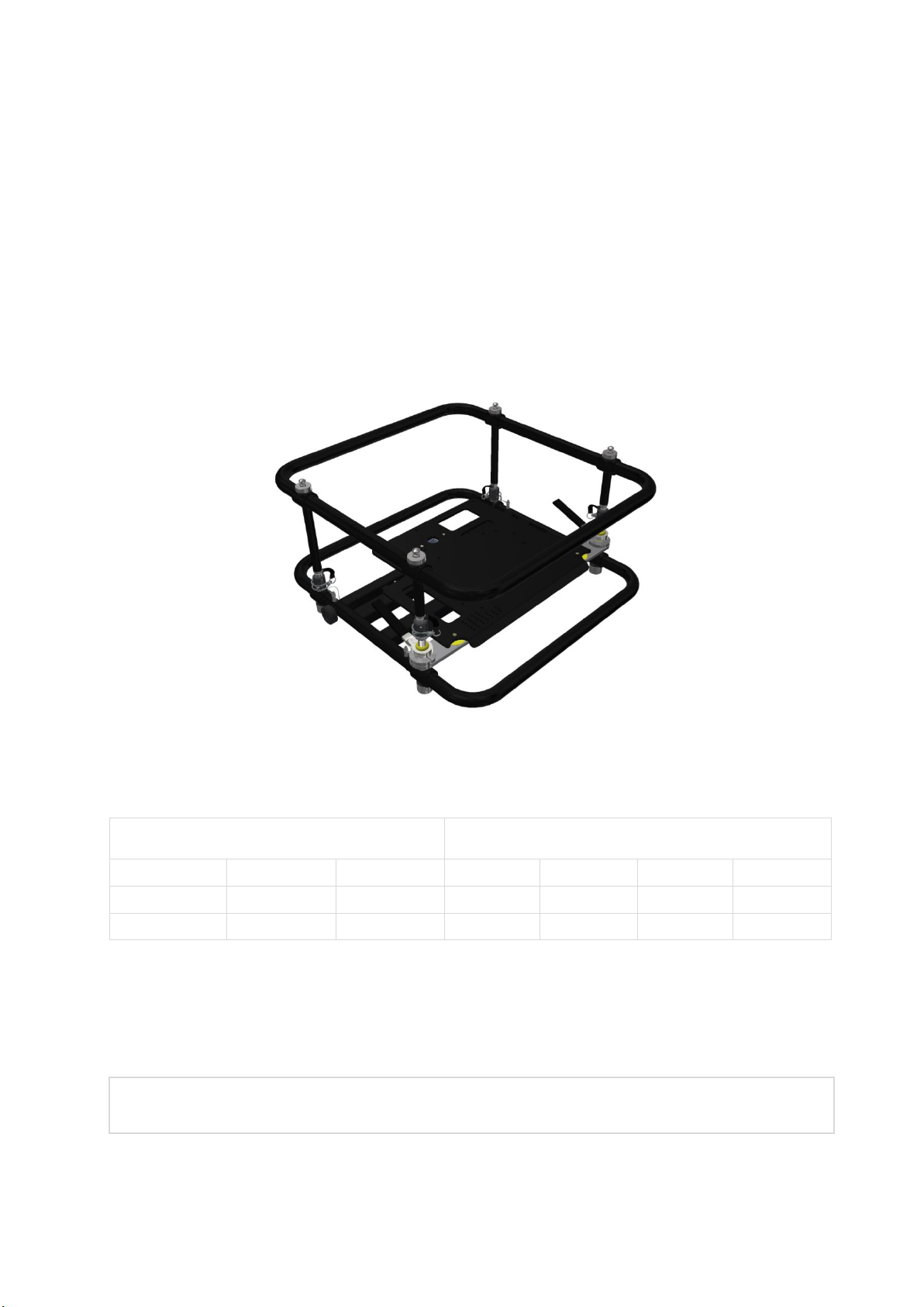
FRAME-EVO-P10 / P10-US
Mounting frame for projectors
The following projectors can be mounted in this frame:
3 Chip DLP*
1 Chip DLP*
PT-DZ13K
PT-DS12K
PT-DW11K
PT-RZ120
PT-RZ870
PT-RZ660
PT-RCQ10
PT-DZ110XE
PT-DS100XE
PT-DW90XE
PT-RZ970
PT-RW930
PT-RZ770
PT-RCQ80
PT-DZ10K
PT-DZ870
PT-DZ780
PT-RX110
* All compatible projector models can be found on page 15.
These installation instructions must always be provided to the customer

Manual FRAME-EVO-P10 / P10-US
Version 1.6
02.09.2019
Page 1of 39

Manual FRAME-EVO-P10 / P10-US
Version 1.6
02.09.2019
Page 2of 39
Table of content
1. Preamble.................................................................................................... 3
1.1 FRAME-EVO-P10 / P10-US designation......................................................................................... 3
1.2 Optional accessory designation..................................................................................................... 4
1.3 Tools required ............................................................................................................................... 5
2. Safety instructions...................................................................................... 5
3. What’s in the box? ....................................................................................10
4. Optional Accessories .................................................................................11
5. Fitting the projectors in the frame.............................................................13
6. Removing the Upper Ring - Installation Version ........................................17
7. Reinstalling the Upper Ring .......................................................................20
8. Adjustment options...................................................................................22
9. Stacking frames.........................................................................................24
10. Mounting the frame on a truss ................................................................25
11. Maximum stacking information...............................................................27
12. System maintenance and inspection (Re-examination) ...........................33
13. Declaration of Conformity .......................................................................36
14. Dimensions..............................................................................................37
14.1 FRAME-EVO-P10 / P10-US......................................................................................................... 37
14.2 FRAME-EVO-P10 / P10-US Installation Version - without the Upper Ring................................ 38
Imprint..........................................................................................................39

Manual FRAME-EVO-P10 / P10-US
Version 1.6
02.09.2019
Page 3of 39
1. Preamble
Congratulations on your purchase of the FRAME-EVO-P10 / P10-US projector frame from
LANG AG.
Please read very carefully the instructions provided in this manual. In the following pages
you will find all the information needed for a safe and fast installation.
After the installation is done properly, you can enjoy all the features of your new product.
Please consider keeping the original box and packaging materials, in case you ever need to
ship the frame.
Model number: FRAME-EVO-P10 / P10-US
1.1 FRAME-EVO-P10 / P10-US designation
European market
Non-European market
Manufacturer m.no.: FRAME-EVO-P10
Panasonic EU m.no.: ET-RFD40
Manufacturer m.no.: FRAME-EVO-P10-US
Panasonic USA m.no.: ET-PFD365
m.no. = model number
Note: In this manual, when reference is made to the manufacturer model number it is also
automatically a reference to the Panasonic EU / USA model number like described in the
table above

Manual FRAME-EVO-P10 / P10-US
Version 1.6
02.09.2019
Page 4of 39
1.2 Optional accessory designation
European market
Non-European market
Manufacturer m.no.: FRAME-PF-UNI-PORAD
Panasonic EU m.no.: ET-CLP-P
Manufacturer m.no.: FRAME-PF-UNI-PORAD
Panasonic USA m.no.: - (non-USA product)
Manufacturer m.no.: FRAME-PF-UNI-CLP5030
Panasonic EU m.no.: ET-CLP50
Manufacturer m.no.: FRAME-PF-UNI-CLP5030
Panasonic USA m.no.: ET-PFD50CLAMP
Manufacturer m.no.: FRAME-PF-UNI-CLP30PT
Panasonic EU m.no.: ET-CLP30
Manufacturer m.no.: FRAME-PF-UNI-CLP30PT
Panasonic USA m.no.: ET-PFD30CLAMP
Manufacturer m.no.: TH-SHORT-150-8
Panasonic EU m.no.: ET-SHT150
Manufacturer m.no.: TH-SHORT-150-8
Panasonic USA m.no.: ET-PFD550TMS2
Manufacturer m.no.: TH-SHORT-60-6
Panasonic EU m.no.: ET-SHT60
Manufacturer m.no.: TH-SHORT-60-6
Panasonic USA m.no.: - (non-USA product)
m.no. = model number
Note: In this manual, when reference is made to the manufacturer model number it is also
automatically a reference to the Panasonic EU / USA model number like described in the
table above.

Manual FRAME-EVO-P10 / P10-US
Version 1.6
02.09.2019
Page 5of 39
1.3 Tools required
The only tool required is a 4 mm hex key to mount the projector in the FRAME-EVO-P10 /
P10-US.
These installation instructions must always be handed over to the installing person.
1
Read these instructions carefully before installing the system.
Copyright © 2018 LANG AG. All rights reserved.
2. Safety instructions
INTENDED USE
The FRAME-EVO-P10 / P10-US frame is intended for use by fully qualified, trained and
competent persons to provide safe and secure transportation, installation and adjustment
of projectors.
Only use the frame with projector in a closed environment (conference rooms, theatres,
convention halls, etc.) where there is no wind, moisture, excessive heat etc.
Make sure that only the corresponding projectors are installed in this frame! Do not try to
use it with other projectors because serious accidents can occur!
1
Only a qualified person should install this product
4 mm hex key (Allen key)
Manual FRAME-EVO-P10 / P10-US
Version 1.6
02.09.2019
Page 6of 39
WARNINGS
Installation work should only be carried out by a qualified technician.
•If this product is not installed correctly, serious accidents may result.
Do not use the FRAME-EVO-P10 / P10-US frame outdoors.
•This product is made only for indoor usage. If the FRAME-EVO-P10 / P10-US frame is
mounted outdoor, there are many influences like wind or rain that can have an effect
on the stability of the whole system. This can cause serious accidents and property
damage.
Do not place the frame on top of unstable surfaces.
•If the frame is placed on top of a surface which is sloped or unstable, it may fall down
or tip over and injury or damage could result. Make sure that the surface can support
a load of 175 kg (385.81 lbs)
2
plus the weight of all additional equipment as well as
other potential systems.
Do not hang the frame from unstable or inappropriate structures.
•If the frame is hung on an unstable structure, the entire system can fall down and
injuries may occur. Make sure that the construction can support a total weight of 175
kg (385.81 lbs) plus the weight of all additional equipment as well as other potential
systems.
Make sure to not exceed max. weight loads for ceiling mounting.
•For suspended installations, use only designated hanging accessories, like TH-SHORT-
150-8, TH-SHORT-60-6, FRAME-PF-UNI-PORAD Portrait Adapter and FRAME-PF-UNI-
CLP5030, FRAME-PF-UNI-CLP30PT rigging clamps for a max. weight load of 175 kg
(385.81 lbs). Please refer to the corresponding instructions for the accessories used.
Please also refer to chapter “4. Optional Accessories” and “11. Maximum stacking
information”.
2
175 kg (385.81 lbs) = 3 x (weight of heaviest projector + weight of heaviest lens + weight of FRAME-EVO-P10 / P10-US)
Manual FRAME-EVO-P10 / P10-US
Version 1.6
02.09.2019
Page 7of 39
For stacking, make sure that all four locking pins pass completely through the female
stacking bolt.
•Make sure the four male bolts enter into the correspondent female bolts and are
locked.
Do not install the FRAME-EVO-P10 / P10-US or the projector while people are present
under the mounting zone during the installation process.
•When installing the projector, make sure no one is in the area underneath the
installation zone.
Always secure the frame to the rigging truss with a safety steel cable.
•The frame should always be secured with an appropriate safety steel cable so that in
case of a malfunction it doesn’t fall more than 5 cm. Please consult the local laws or
regulations regarding the additional safety of hanging equipment.
CAUTION
Before installing the projector in the FRAME-EVO-P10 / P10-US frame, please read the
projector’s user manual. When the projector has a lens attached, please remove it.
•The FRAME-EVO-P10 / P10-US frame with the projector inside must be installed only
in an environment that is recommended by the projector manufacturer.
Minimum two persons are required to install the FRAME-EVO-P10 / P10-US frame.
•With regard to the overall weight of all necessary installation devices, make sure to
handle those with at least two people.
Make sure that the structure from which you hang up to 3 FRAME-EVO-P10 / P10-US
frames including projectors is capable of carrying the overall weight of approx. 175 kg
(385.81 lbs) plus the weight of all additional equipment as well as other potential systems.
•Prior to any installation, you must do a visual inspection to make sure that the
system is in a good condition. For more information please refer to chapter
“12. System maintenance and inspection (Re-examination)”.

Manual FRAME-EVO-P10 / P10-US
Version 1.6
02.09.2019
Page 8of 39
RISK SITUATIONS
Risk of injury due to the possibility of falling objects during the assembly or disassembly of
the FRAME-EVO-P10 / P10-US frame.
•Protection objective: avoid injury from falling parts.
•Wear appropriate safety shoes, gloves and helmet.
•Make sure the area is clear under the frame during installation.
Risk of hitting the head with the FRAME-EVO-P10 / P10-US frame during the hanging set
up process.
•Protection objective: avoid injury from hitting the head.
•Wear a helmet.
Incorrect installation may lead to certain parts of the FRAME-EVO-P10 / P10-US frame or
the entire FRAME-EVO-P10 / P10-USframe to fall down.
•Protection objective: prevent personal injury and property damage.
•Double check the FRAME-EVO-P10 / P10-US frame and its installation.
Insufficient load capacity of the supporting structure may lead to certain parts of the
FRAME-EVO-P10 / P10-US frame or the entire FRAME-EVO-P10 / P10-US frame to fall
down.
•Protection objective: prevent personal injury and property damage.
•Provide adequate dimensioning of the supporting structure. The supporting structure
must be able to support the combined weight of all the equipment attached to, or
hung from it.
•Ensure correct installation of the supporting structure.

Manual FRAME-EVO-P10 / P10-US
Version 1.6
02.09.2019
Page 9of 39
The fingers or the hand of the user can be caught between the outer rings and the plates
or projector.
•Protection objective: Prevent personal injury by using safety gloves.
•When the adjustment of the image is made, the user must always keep his hands on
the hand levers (see picture below).
•Because the spring of the spring clip is strong, please be careful not to clamp your
fingers between the spring and the attachment nut.
Manual FRAME-EVO-P10 / P10-US
Version 1.6
02.09.2019
Page 10 of 39
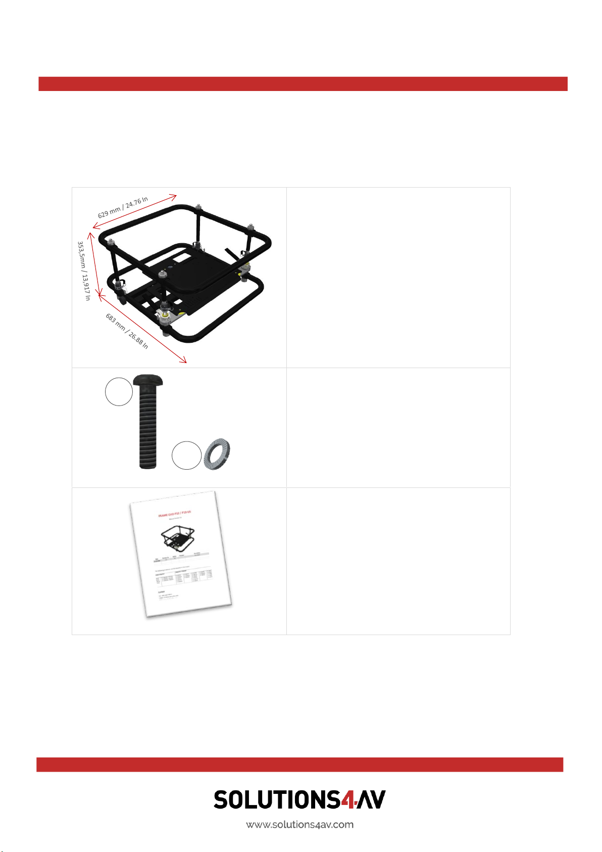
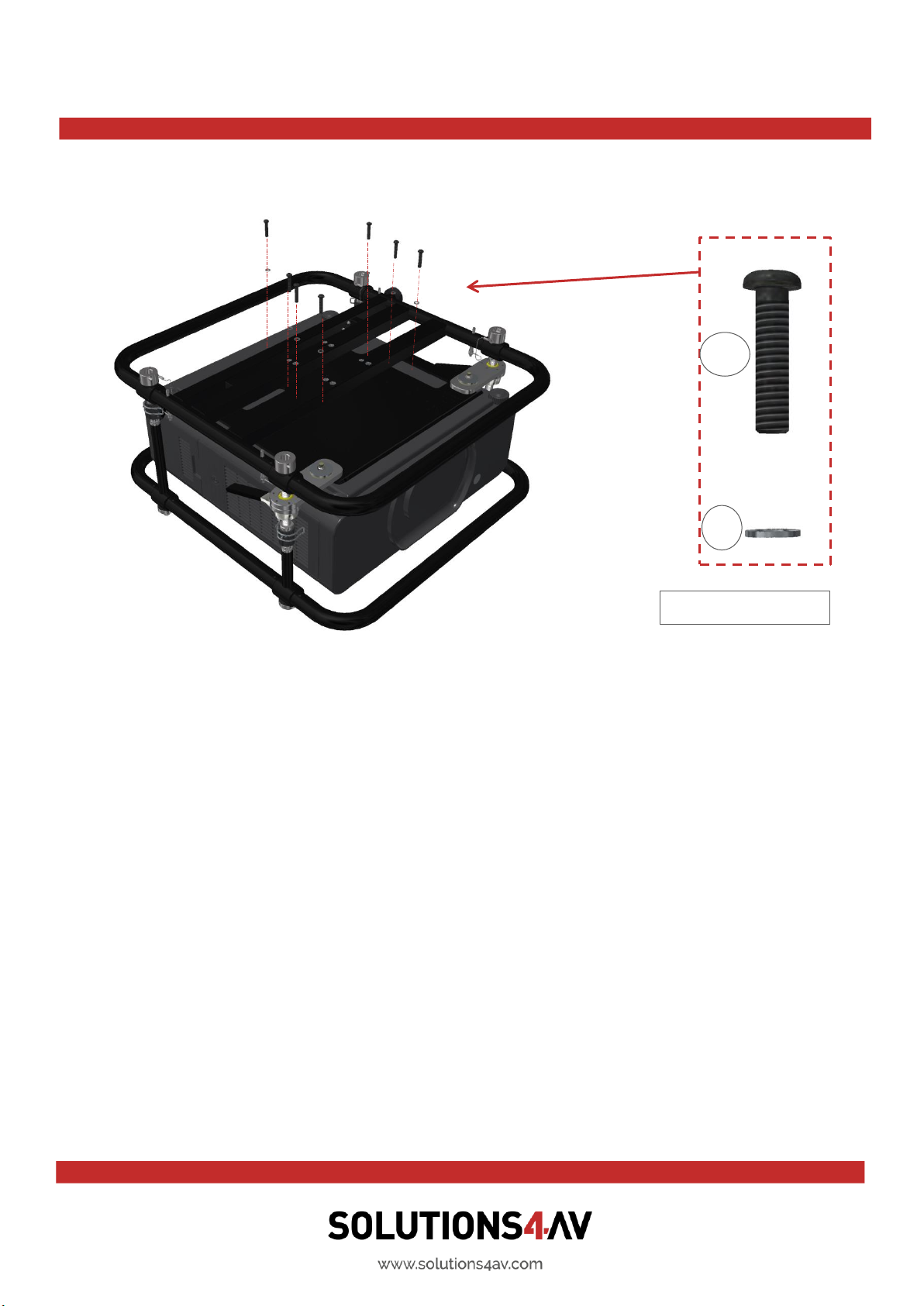
3. What’s in the box?
FRAME-EVO-P10 / P10-US
•Used for projector installation
•Number of units: 1
•Weight: 13,4 kg / 29.54 lbs
1) 7 x M6x20 ISO 7380 screws
(galvanized steel 10.9)
2) 7 x Ø6 Schnorr Washer
Used to secure the projector
in the frame
User manual and installation guide
for FRAME-EVO-P10 / P10-US
Make sure your box contains everything you ordered. If any pieces are missing, contact the
vendor.
1
2
Manual FRAME-EVO-P10 / P10-US
Version 1.6
02.09.2019
Page 11 of 39
4. Optional Accessories
Please refer to “1.1 FRAME-EVO-P10 / P10-US designation”to assign the Panasonic EU and
USA model numbers to the model numbers below.
Please refer to chapter “10. Mounting the frame on a truss” and the following for
information regarding the usability of the optional accessories.
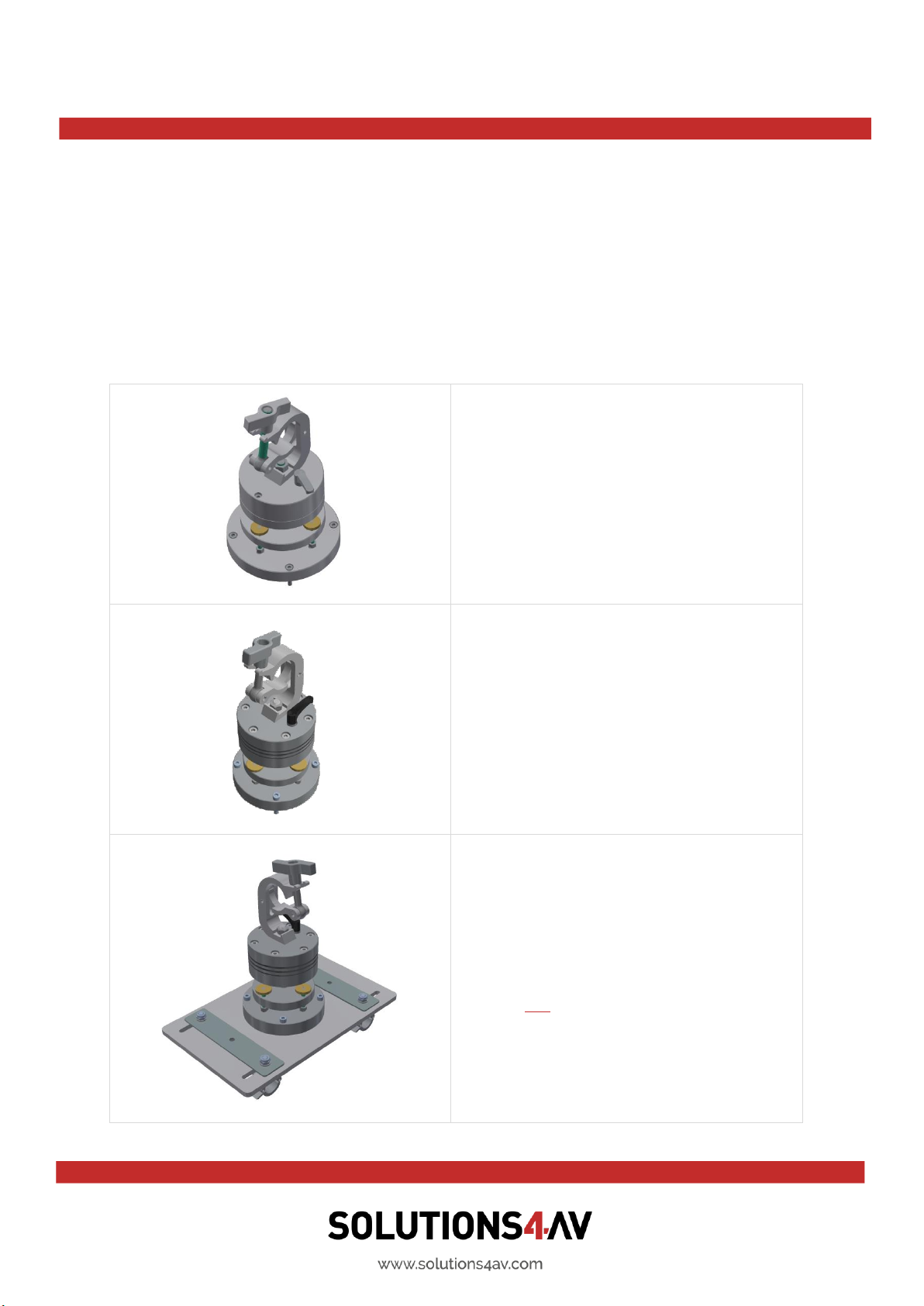
TH-SHORT-60-6
Optional accessory for truss mount
installations.
More information can be found in the TH-
SHORT-60-6 Installation manual.
TH-SHORT-150-8
Optional accessory for truss mount
installations.
More information can be found in the TH-
SHORT-150-8 Installation manual.
FRAME-PF-UNI-PORAD
Portrait Adapter for Projector Frames
Optional accessory for portrait mode truss
mount installations.
Does not include the TH-SHORT-150-8
More information can be found in the
FRAME-PF-UNI-PORAD installation manual.
Manual FRAME-EVO-P10 / P10-US
Version 1.6
02.09.2019
Page 12 of 39
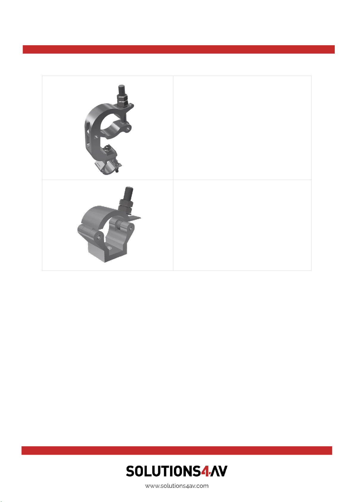
FRAME-PF-UNI-CLP5030
Optional accessory for hanging one FRAME-
EVO-P10 / P10-US or two in tandem mode
on a truss.
FRAME-PF-UNI-CLP5030 represents a
complete set of 4 pieces.
FRAME-PF-UNI-CLP30PT
Optional accessory for portrait mode table
installation.
FRAME-PF-UNI-CLP30PT represents a
complete set of 4 pieces.
The optional accessories must be purchased separately. They are not included in the
standard package!
Manual FRAME-EVO-P10 / P10-US
Version 1.6
02.09.2019
Page 13 of 39
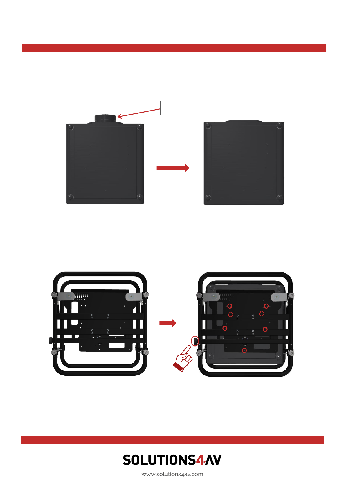
5. Fitting the projectors in the frame
Step 1: Place the projector upside down on a suitable flat surface then remove the lens
(if it is pre-installed). For easier access you may first remove the upper ring before mounting
the projector. Please refer to chapter “6. Removing the Upper Ring - Installation Version”.
Otherwise it is recommended to place an appropriate material underneath the projector so
that it is lifted up for about 10 cm. This will help during the following process.
Step 2: Position the frame over the projector so that the adjustment screw is at the back,
aligning the M6 screw holes. Please put the projector in the right position so that the
front/back position is correct when installing. Otherweise the position of the holes will not
match.
Lens

Manual FRAME-EVO-P10 / P10-US
Version 1.6
02.09.2019
Page 14 of 39
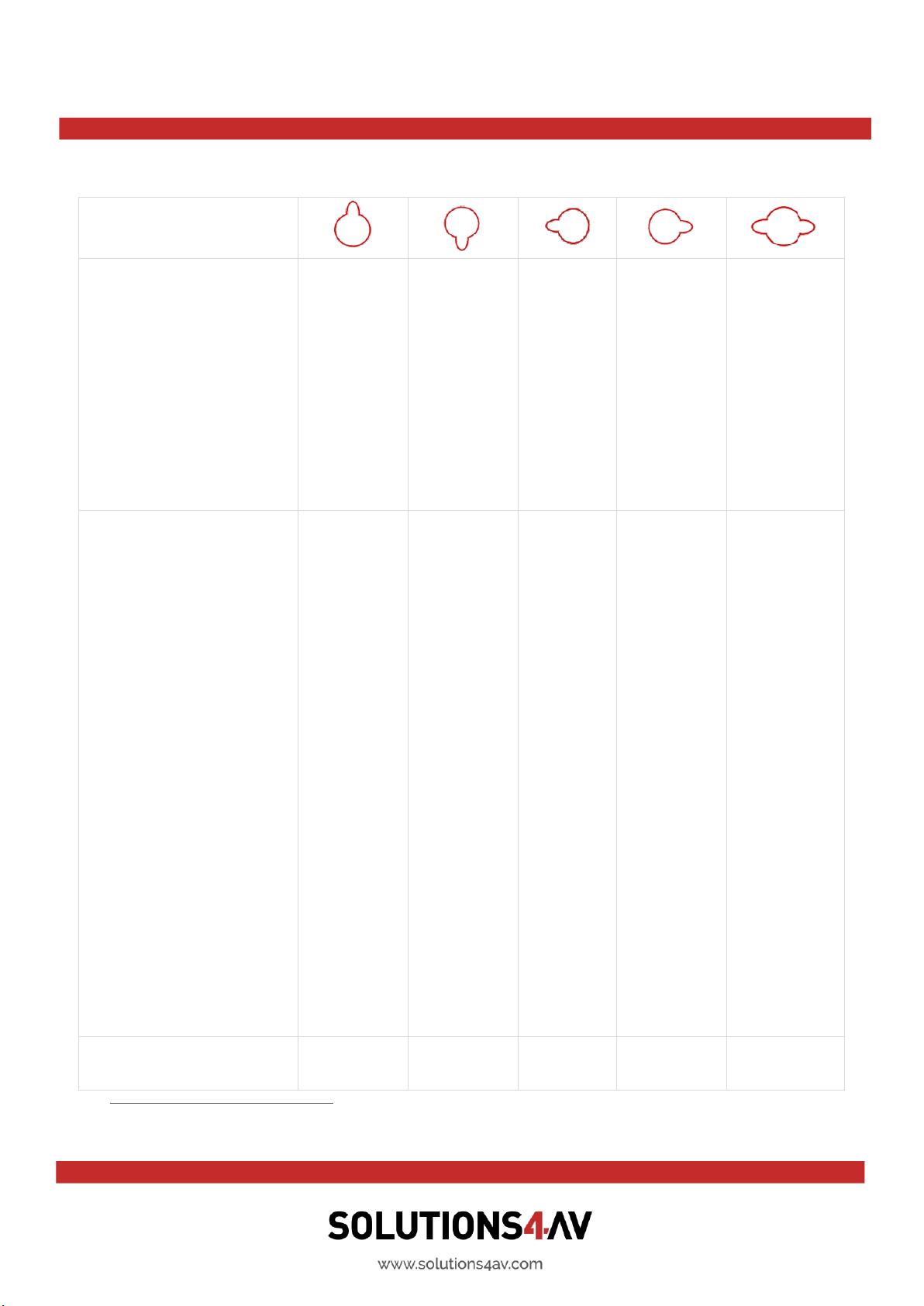
Because a smooth and easy installation of all the compatible projectors in the FRAME-EVO-
P10 / P10-US is required, the base plate was design with a variety of symbols.
A list with the corresponding symbols can be found on the following page.
Manual FRAME-EVO-P10 / P10-US
Version 1.6
02.09.2019
Page 15 of 39
Symbols on FRAME-EVO-
P10 / P10-US base plate:
3
These projector models
can be mounted with
included screws:
PT-DZ780
PT-DZ13K
PT-DS12K
PT-DW11K
PT-DZ10K
PT-DZ110XE/
PT-DZ8700U
PT-DS100XE/
PT-DS8500U
PT-DW90XE/
PT-DW8300U
PT-RZ970
PT-RZ870
PT-RZ770
PT-RZ660
PT-RZ120
PT-RW930
PT-RX110
PT-RCQ10
PT-RCQ80
PT-DZ870
PT-RZ970*
PT-RZ870*
PT-RZ770*
PT-RZ660*
PT-RZ120*
PT-RW930*
PT-RX110*
PT-DZ780*
PT-DZ870**
PT-RCQ10*
PT-RCQ80*
Please check threads
at projector side,
2 mm shorter screws
may be needed for these
projector models:
PT-DZ770
PT-DW740
PT-DX810
PT-DW730
PT-DX800
PT-DZ680
PT-DW640
PT-DX610
PT-DZ6710
PT-DZ6700
PT-DW6300
PT-D6000
PT-D5000
PT-DW750
PT-DX820
PT-DW750
PT-DZ770
PT-RW730
PT-RW620
PT-RZ670
PT-RW630
PT-DW830
PT-DX100
PT-RW730*
PT-RW620*
PT-RZ670*
PT-RW630*
PT-DZ770*
PT-DW740*
PT-DX810*
PT-DW730*
PT-DX800*
PT-DZ680*
PT-DW640*
PT-DX610*
PT-DZ6710*
PT-DZ6700*
PT-DW6300*
PT-D6000*
PT-D5000*
PT-DW750*
PT-DX820*
PT-DW750*
PT-DZ770*
PT-DW830**
PT-DX100**
Number of screws:
5
7
5
6
*5
**6
3
This symbol represents the common hole shared by two types of projectors.
Manual FRAME-EVO-P10 / P10-US
Version 1.6
02.09.2019
Page 16 of 39
Step 3: Place the recommended number of Ø6 Schnorr Washers (2) over each
corresponding hole. Secure the recommended number of M6x20 ISO 7380 screws (1) into
each hole with 4 Nm torque. Ensure each screw runs through the plate and catches into the
corresponding M6 hole in the projector surface. Please make sure to use only the
correspondent screw holes when installing a projector!
Do not forget to use the Ø6 Schnorr Washers (2) as they are preventing the screws to loose
themselves!
In case you removed the upper ring during Step 1 please now refer to chapter
“7. Reinstalling the Upper Ring”and attach the upper ring back to the base.
Step 4: The lens can be attached back to the projector.
Torque: 4±0.5 Nm
1
2

Manual FRAME-EVO-P10 / P10-US
Version 1.6
02.09.2019
Page 17 of 39
6. Removing the Upper Ring - Installation Version
The purpose of the Installation Version is to have a quick, simple and tool free possibility to
install the ET-D75LE90 or ET-D75LE95 ultra-short throw lens, or any other short throw
lenses, without any limitation regarding the frame.
Step 1: Remove the 4 x spring clips as presented in the above picture. Because the spring of
the spring clip is strong, please be careful not to clamp your fingers between the spring and
the attachment nut

Manual FRAME-EVO-P10 / P10-US
Version 1.6
02.09.2019
Page 18 of 39
Step 2: Unscrew the 4 x attachment nuts (as presented in the above picture) until they are
completely loose and can be move up and down freely.
Step 3: Remove the Upper Ring and you will have the Installation Version of the frame

Manual FRAME-EVO-P10 / P10-US
Version 1.6
02.09.2019
Page 19 of 39
Step 4: Now the ET-D75LE90 or ET-D75LE95 ultra-short throw lens can be attached to the
projector
This manual suits for next models
3
Table of contents
Other Solutions4AV Projector Accessories manuals


Popular Projector Accessories manuals by other brands


Navitar
Navitar 585MCZ500 installation instructions

Navitar
Navitar 641MCL1028 installation instructions

Da-Lite
Da-Lite Dual Masking Electrol Instruction book

QualGear
QualGear QG-PRO-PM-CA-B installation manual

Christie
Christie 140-133108 Series instruction sheet

Key Digital
Key Digital FATCAT Series operating instructions


