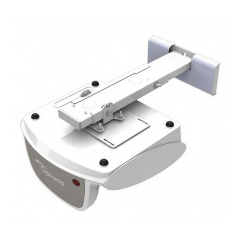
Optoma OWM3000 User manual

OWM3000
Ultra short throw
projector mount

English............2-6
Deutsch...........7-11
Français..........12-16
Italiano............17-21
1
Contents

B
NO
C
D
E
A
5
5
1
F
4
1
4
Support Arm x 1
Wall Plate x 1
Projector Mounting
Plate x 1
Wall Cover x 1
Wall Plate Cover x 1
diagrammatic
presentation
quantity
Screw(M6x55)
Αnchor bolt
L5 Allen key
L3 Allen key
Screw(M4x8)
Screw(M6x15)
Package Overview
Step 1: Attach the wall plate to the wall
● For concrete wall mounting, thickness of the wall must be not less than 4'' (100mm). Anchor bolt and
screw (M6x55) are needed to be used for concrete wall installation.
● For Dry-wall mounting, thickness of the dry-wall must be not less than 4.5" (114mm). Only screw (M6x55)
is needed to be used for installation, and gypsum board thickness less than 0.59" (15mm).
Note: If the thickness of wall is not strong enough, reinforce it sufficiently before installation.
Specification
2
Fixing Kit
● If the board has been installed, please align the center line of the projector lens on the installation chart with
that of the screen or board to the locate the place of the mount period.
1080P(1920x1080)
Safety

≥55mm
B
≥55mm
Concrete wall mounting With anchor bolt Dry-wall mounting
Without anchor bolt
Ø10-11mm Ø3mm
C
A
C
A
The arrows up The arrows up
screw centre
When installed on the
wood stud wall, align the
center of the wall mount
plate with the center of
the stud.
Step 2: Attach the projector mount to the wall plate
D
CF
The cables The cables
The cables
Loosen the screws with L3 allen wrench,
pull out the support arm around 4'' (100mm)
and make power cable & signal cables go
through the support arm.
The cables can go through the wall plate
by three ways as shown in the pictures. Then,
tighten the screw F after locating the position
of the projector mount period.
3
● Insert Screw F(M6x15) from the fixing kit, tighten with a L5 Allen Key from fixing kit.
● Insert Screw A(M6x55) from the fixing kit, tighten with a L5 Allen Key from fixing kit.
≥100mm ≥114mm

Step 3: Attach the projector to mount plate and to the mount
4
Take off the cap
Loosen the screw
● Loosen the screw on the mount and pre-tighten the projector on the mount.
Step 4: Adjusting the image horizontally
A
A
B
B
Screen Adjustment Direction
to the projector
Tighten the screws Connect power cable and other signal cable
E
Slide the mount plate
AB
Power cable
Signal cable

5
Step 5: Adjusting the image size
To make adjustments to meet your demands, screws must be loosened in a specific
order, as shown in the above Fig① ,Fig②. (When the length of inside arm 555mm do not meet
your demands, then you should loose the screws on the outside arm to adjust the middle arm.
Under this circumstance, the number read on the middle arm is correct).
Step 6: Adjusting the image height
A
B
A
● Loosen the screws slightly to adjust the projector to the required position.
Step 7: Adjusting the vertical tilt
AB
A
B
Adjustment
Direction
Vertical tilt Knob
Screen
Note:
A
B
F
C
A
B
B
Screen
Adjustment
Direction
to see the distance from
wall to the mounting plate
Check the measuring rule
35
880mm
590mm
23in
①
970mm
38in
②
D
B
A
A
B
Screen Adjustment Direction

or
1
1
2
1
2
3
: When all adjustments are done, the wall plate covers can be used to cover the blank
area on the top of wall plate. The number of wall plate cover used depends on the size of
blank area. But the wall cover must be used in an specific order as the picture on left shows.
AB
A
B
Screen Adjustment Direction
Step 8: Adjusting the horizontal roll
AB
AB
Horizontal Roll Knob Screen Adjustment Direction
Step 9: Adjusting the horizontal rotation
Horizontal Rotation Knob
Step 10: Using the decorative covers
Finally, put the wall cover on.
Product Information
6
Net Weight
Weight Capacity
Extendable Length
Adjustment Angle
5.0kg(11lb)
15.0kg(33lb)
325mm-740mm(12.8-29in)
±
5°
Verticaltilt, Horizontal roll, Horizontal rotation
AB
AB
Note
1
2
3
4
Wall plate covers

Halterung für
Ultrakurzdistanzprojektoren
Gebrauchsanleitung

B
NO
C
D
E
A
5
5
1
F
4
1
4
Stützarm
x 1
Wandplatte x 1
Projektor
Befestigungsplatte x 1
Wandabdeckung x 1
Abdeckung
Wandplatte x 1
diagrammatic
presentation
quantity
Schraube
(M6x55)
Dübel
L5 Inbusschlüssel
L3 Inbusschlüssel
Schraube(M4x8)
Schraube(M6x15)
Lieferumfang
Schritt 1: Befestigen Sie die Wandplatte an der Wand
● Achten Sie bei der Installation an Betonwänden darauf, dass diese nicht dünner als 100mm sind und nutzen
Sie einen Dübel mit passender Schraube.
● Achten Sie bei der Installation an Trockenbauwänden darauf, dass diese nicht dünner als. 114mm sind und
bei Gipswänden nicht dünner als 15mm. In beiden Fällen reicht eine Schraube (M6x55) zur Befestigung.
Hinweis: Sollte die Wand nicht dick genug sein, verstärken Sie sie bitte entsprechend vor der Installation.
Specification
7
Befestigungsset
1080P(1920 x108 0)
Sicherheit
Lesen Sie diese Sicherheitshinweise sorgfältig durch, bevor sie mit der Installation beginnen
Installieren Sie die Halterung an einer geeigneten Stelle mit den passenden Befestigungen.
Sollten Sie an der Beschaffenheit der gewählten Wand Zweifel haben, wenden Sie sich
bitte an einen Fachmann.
Nutzen Sie alle verfügbaren Befestigungspunkte.
Versuchen Sie auf keinen Fall, die Wandhalterung oder Teile davon zu verändern oder
zu modifizieren.
Nutzen Sie die Halterung nicht, wenn Teile beschädigt oder kaputt sein können.
Ziehen Sie alle Schrauben und Befestigungen fest an
Nutzen Sie nur die mitgelieferten Befestigungen.
Befestigen Sie den Projektor nicht in der Nähe von Feuchtigkeits- oder Hitzequellen.
Installieren Sie den Projektor und die Halterung immer mindestens zu zweit
≥55mm
B
≥55mm
Befestigung an Betonwand Mit Dübel Befestigung an Trockenbauwand
ohne Dübel
Ø10-11mm Ø3mm
C
A
C
A
Pfeile nach oben
Pfeile nach oben
Bei Befestigung an einer
Holzwand mit Stütze
positionieren Sie die Mitte
der Halterung in der
Mitte der Stütze.
Schritt 2: Befestigen Sie die Projektorhalterung an der Wandplatte
D
CF
Die Kabel Die Kabel
Die Kabel
Lösen Sie die Schrauben mit einem
L3 Imbus Schlüssel, ziehen Sie den
Arm ca. 100mm heraus und führen
Sie das Strom-, sowie Signalkabel
Die Kabel können auf die drei
abgebildeten Arten geführt werden. Nach
finaler Positionierung der Halterung
ziehen Sie Schraube F fest.
8
● Schrauben Sie Schraube F (M6x15) aus dem Befestigungsset ein und ziehen
Sie sie mit Imbus Schlüssel L5 fest.
● Schrauben Sie Schraube A (M6x55) vom Befestigungsset in die Wand und ziehen
Sie sie mit einem L5 Imbus Schlüssel aus dem Befestigungsset fest.
≥100mm ≥114mm
durch den Arm.

Schritt 3: Befestigen Sie den Projektor an der Befestigungsplatte
und der Halterung
9
Abdeckung abnehmen
Lösen Sie die
Schrauben fest
● Lösen Sie die Schraube an der Halterung und befestigen Sie den Projektor an der Halterung
Schritt 4:Horizontale Anpassung des Bildes
A
A
B
B
Richtungsanpassung des Bildes
Projektor an
Ziehen Sie die Schrauben fest Schließen Sie Strom- und Signalkabel an den
E
Schieben Sie die Halterungsplatte
AB
Stromkabel
Signalkabel

10
Schritt 5: Vorwärts- und Rückwärtsbewegungen einstellen
Um die Halterung nach Ihren Ansprüchen einzustellen, müssen die Schrauben in wie in
Abb ① und ②angegeben gelöst werden. (Sollte die Länge des inneren Arms von 555mm
nicht reichen,dann sollten Sie die Schrauben am Außen Arm lösen, um den mittleren Arm
anzupassen. In diesem Fall ist die Zahl, die auf dem mittlerem Arm abzulesen ist, korrekt.).
Schritt 6: Auf- und Ab Bewegungen einstellen
A
B
A
● Lösen Sie die Schrauben leicht, um den Projektor in die gewünschte Position zu bringen.
Schritt 7: Die vertikale Neigung einstellen
AB
A
B
Bildes
vertikale Neigung einstellen
des
Richtungsanpassung
Hinweis:
A
B
F
C
A
B
B
Richtungsanpassung
des
Bildes
Maßeinheiten den Abstand von der
Wand zur Halterungsplatte
Überprüfen Sie anhand der
35
880mm
590mm
23in
①
970mm
38in
②
D
B
A
A
B
Richtungsanpassung des Bildes

1
1
2
1
2
3
:Wenn Sie mit der Installation fertig sind, können die Wandplattenabdeckungen Hinweis
an die Wandplatte angebracht werden. Die Anzahl der Abdeckungen hängt von der Größe
der abzudeckenden Fläche ab, aber die Wandabdeckung muss in einer bestimmten Folge
AB
A
B
Richtungsanpassung des Bildes
Schritt 8: Die horizontale Rollbewegung einstellen
AB
AB
horizontale Rollbewegung einstellen Richtungsanpassung des Bildes
Schritt 9: Die horizontale Rotation einstellen
horizontale Rotation einstellen
Schritt 10: Die Wandplatte abdecken
angebracht warden (siehe Abbildung).
Produktinformation
11
Netto Gewicht
Maximal Gewicht
Ausziehbare Länge
Einstellungswinkel
5.0kg
15.0kg
325mm-740mm
Vertikale Neigung, horizontale Drehung, horizontale Rotation±5 °
AB
AB
1
2
3
4
Abdeckung Wandplatte

Support
Projecteur Ultra Courte Focale
Manuel Utilisateur

Bras du Support
x 1
Plaque Mural x 1
Plaque de
fixation du projecteurx 1
Cache Mural x 1
Couvercle pour
plaque Murale x 1
Contenu de l’emballage
Etape 1: Fixer la plaque murale au mur
● Pour un montage sur un mur en béton, l’épaisseur du mur ne doit pas excéder 100mm. Vis et boulon
d’ancrage (M6x55) sont nécessaires pour une installation sur un mur en béton.
● Pour un montage sur une cloison sèche, l’épaisseur du mur ne doit pas excéder 114mm. Seulement une
vis (M6x55) est nécessaire pour l’installation. L’épaisseur du panneau de plate de doit pas
Note: SI l’épaisseur du mur n’est pas suffisante, renforcez-le suffisamment avant toute installation.
B
NO
C
D
E
A
5
5
1
F
4
1
4
diagrammatic
presentation
quantity
Vis(M6x55)
Boulon d'ancrage
Clé Allen L5
Clé Allen L3
Vis(M4x8)
Vis
(M6x15)
Specification
12
Kit de fixation
1080P(1920x1080)
Sécurité
Lisez les instructions avec précaution avant l’installation de votre matériel.
Installez le support plafond avec des fixations adaptées à la structure et au type de votre mur.
Consultez un constructeur qualifié si vous avez un doute sur la structure de votre mur.
Utilisez tous les points de fixations disponibles sur votre matériel.
Vous ne devez EN AUCUN CAS modifier ou altérer les différentes pièces du support
et ses fixations.
NE PAS utiliser le support si les pièces sont cassées ou endommagées.
Serrez tous les boulons et fixations solidement.
Vous ne devez utiliser que les fixations fournies avec votre matériel.
Votre vidéoprojecteur NE DOIT PAS être installé à proximité d’une source de chaleur ou
de moisissures.
2 personnes sont obligatoirement nécessaires pour l’installation du support mural et le projecteur
excéder 15mm.

≥55mm
B
≥55mm
Installation sur mur en béton Avec boulon d’ancrage Installation sur cloison sèche
Sans boulon d'ancrage
Ø10-11mm Ø3mm
C
A
C
A
les flèches vers le haut
Lors d’une installation sur
un mur avec des montants
en bois, alignez le centre de
la plaque murale avec
le centre du montant.
Etape 2 : Fixer le support du projecteur à la plaque murale
D
CF
les câbles les câbles
les câbles
Desserrez les vis avec la clé Allen
L3, étendre le bras d’environ
100mm et faites passer le câble
d’alimentation et les câbles de
Les câbles peuvent passer dans la plaque
de fixation de 3 manières comme montré dans
les images. Puis serrer la vis F après avoir
localiser la position du support du projecteur
correctement
13
● Insérez la vis F (M6x15) du kit de fixation, et serrez avec la clé Allen L5.
● Insérez la Vis A (M6x55) présente dans le kit de fixation, serrez avec la clé Allen L5
du kit de fixation
≥100mm ≥114mm
signal dans le bras du support

Etape 3: Fixer le projecteur à la plaque de fixation et au support
14
Retirer le capuchon
Desserrez les vis
● Desserrez les vis sur le support et pré-vissez le projecteur sur le support.
Etape 4: Ajustement de l'image horizontalement
A
A
B
B
Sens d’ajustement de l’écran
câbles vidéo au projecteur
Serrez les vis Connectez le câble d’alimentation et les autres
E
Faites glisser la plaque de fixation
AB
Câble d'alimentation
Câble signal vidéo

15
Etape 5: Ajustement vers l’avant ou l’arrière
Pour ajuster selon vos besoins, les vis doivent être desserrées dans un ordre spécifique,
comme indiqué ci-dessus Fig① ,Fig②. (Lorsque la longueur de bras interne de 555mm
n’est pas suffisante, vous devez alors desserrer les vis sur le bras externe pour ajuster le
bras du milieu. Dans ce cas, le chiffre affiché sur le bras du milieu est correct. )
Etape 6: Ajustement vers le haut ou vers le bas
A
B
A
● Desserrez les vis légèrement pour ajuster le projecteur à la position requise .
Etape 7: Ajustement de l’inclinaison verticale
AB
A
B
de l’écran
de l’inclinaison verticale
d’ajustement
Sens
Note:
A
B
F
C
A
B
B
Sens
d’ajustement
de l’écran
évaluer la distance entre le
mur et la plaque de fixation
Vérifiez la règle de mesure pour
35
880mm
590mm
23in
①
970mm
38in
②
D
B
A
A
B
Sens d’ajustement de l’écran

1
1
2
1
2
3
Lorsque tous les ajustements sont faits, les couvercles peuvent être utilisés pour Note:
couvrir la partie vide en haut de la plaque murale. Le nombre de couvercles utilisés dépend
de la taille de la partie vide. Mais les couvercles doivent être utilisés dans un ordre
AB
A
B
Etape 8: Ajustement du roulement horizontal
AB
AB
du roulement horizontal
Etape 9: Regolazione della rotazione orizzontale
della rotazione orizzontale
Etape 10: Ajoutez les couvercles et caches
spécifique comme indiqué sur l’image de gauche. Enfin, ajoutez le cache mural.
Information produit
16
Poids Net
Capacité de poids
Longueur extensible
Angle d’ajustement
5.0kg
15.0kg
325mm-740mm
Inclinaison verticale, Roulement Horizontal, Rotation Horizontale ±5 °
AB
AB
1
2
3
4
Couvercle pour plaque Murale
Sens d’ajustement de l’écran

Ottica ultra corta
Kit di montaggio proiettore
Manuale utente
Table of contents
Languages:
Other Optoma Projector Accessories manuals

Optoma
Optoma BM-5001U Guide

Optoma
Optoma 3D-RF System User manual

Optoma
Optoma ALR100 Installation guide

Optoma
Optoma EP731 User manual

Optoma
Optoma Projector User manual

Optoma
Optoma BX-AL133B User manual

Optoma
Optoma BM-9005U User manual

Optoma
Optoma 3D-RF System User manual

Optoma
Optoma BX-AL133 User manual

Optoma
Optoma AKPro User manual

Optoma
Optoma OWM1000 User manual

Optoma
Optoma A16 User manual

Optoma
Optoma DS-9106MGA Manual

Optoma
Optoma BM-3300ST User manual

Optoma
Optoma ZF2100 Glasses User manual

Optoma
Optoma UHDCast Pro Quick manual

Optoma
Optoma BX-AL133B User manual

Optoma
Optoma TX778W User manual

Optoma
Optoma 3D-XL Technical manual

Optoma
Optoma 3D-XL User manual