Soluzione Solare Litemeter Pro User manual

Litemeter Pro configuration
Best Practice Installation Manual
Issue 01
Date 11-01-2023
1

Index & About this document
Index
1.Recommended to do during the installation……………………………………………………..3
1.1 Mechanical……………………………………………………………………………………..3
1.2 Electrical……………………………………………………………………………………….4
1.3 Firmware……………………………………………………………………………………….5
2. Not recommended to do during the installation…………………………………………………7
3. MO BUS troubleshooting………………………………………………………………………8
About This Document
Purpose
This document introduces the best installation practices for the configuration set up of Soluzione
Solare sensor – Litemeter 485 PRO by briefly mentioning the recommended and not recommended
practices during the field installation. This document also gives clear instructions related to
troubleshooting of MO BUS 485 configurations.
Intended Audience
This document is intended for consumers of Soluzione Solare sensors and qualified electricians.
2
1.Recommended to do during the installation- Mechanical
1. Recommended to do during the installation
1.1 Mechanical
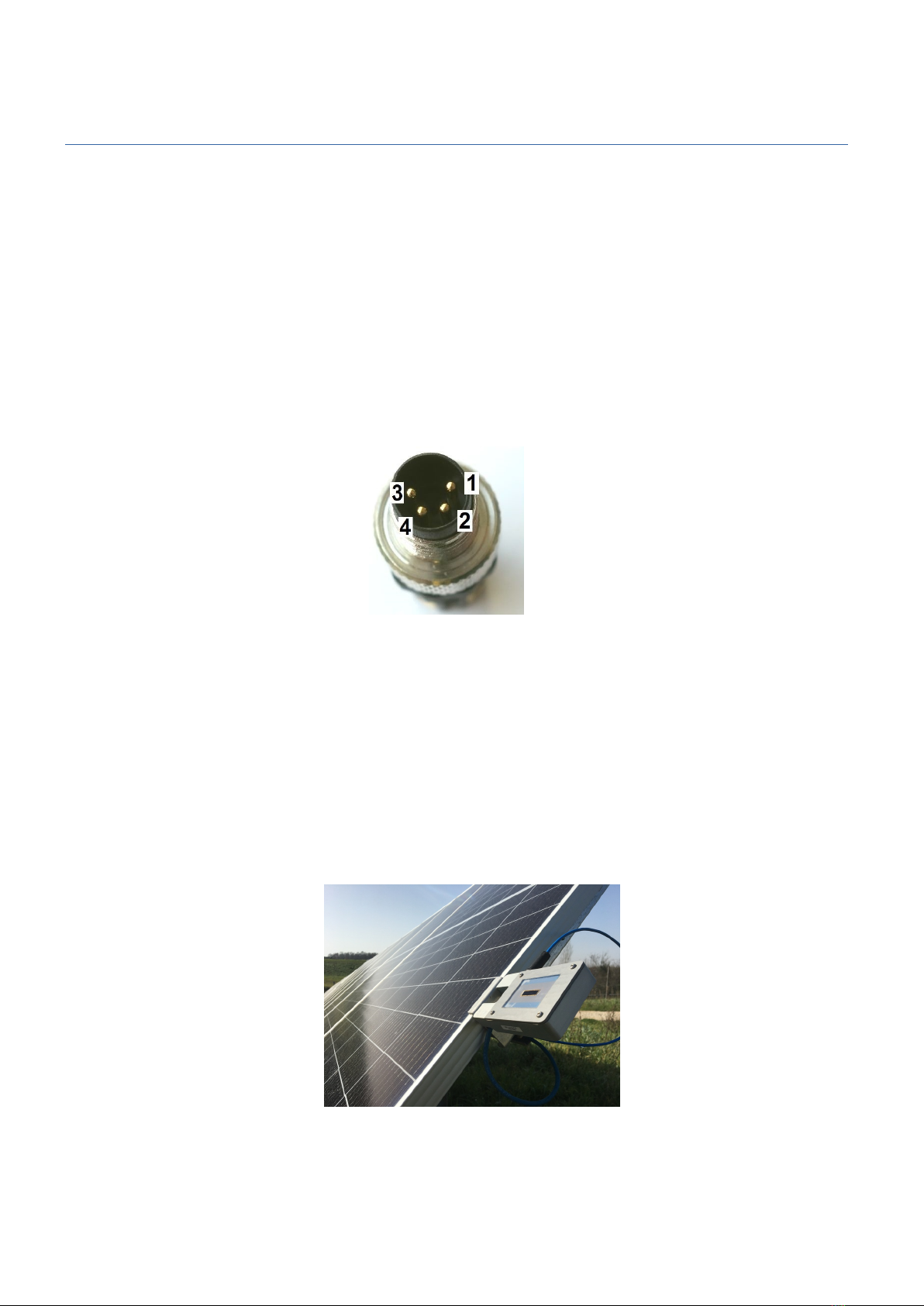
(1) The Litemeter Pro 485 usually comes with a loose pin ends. User can specifically request if
they require a Litemeter Pro 485 manufactured with a male connector end.
(2) In order to get the right fit of male and female side of the connector pin, turn the male side
of the connector less than 360° for finding the right position.
(3) After finding the right position, tighten the connection only by rotating the steel ring and
make sure you do not rotate the connector.
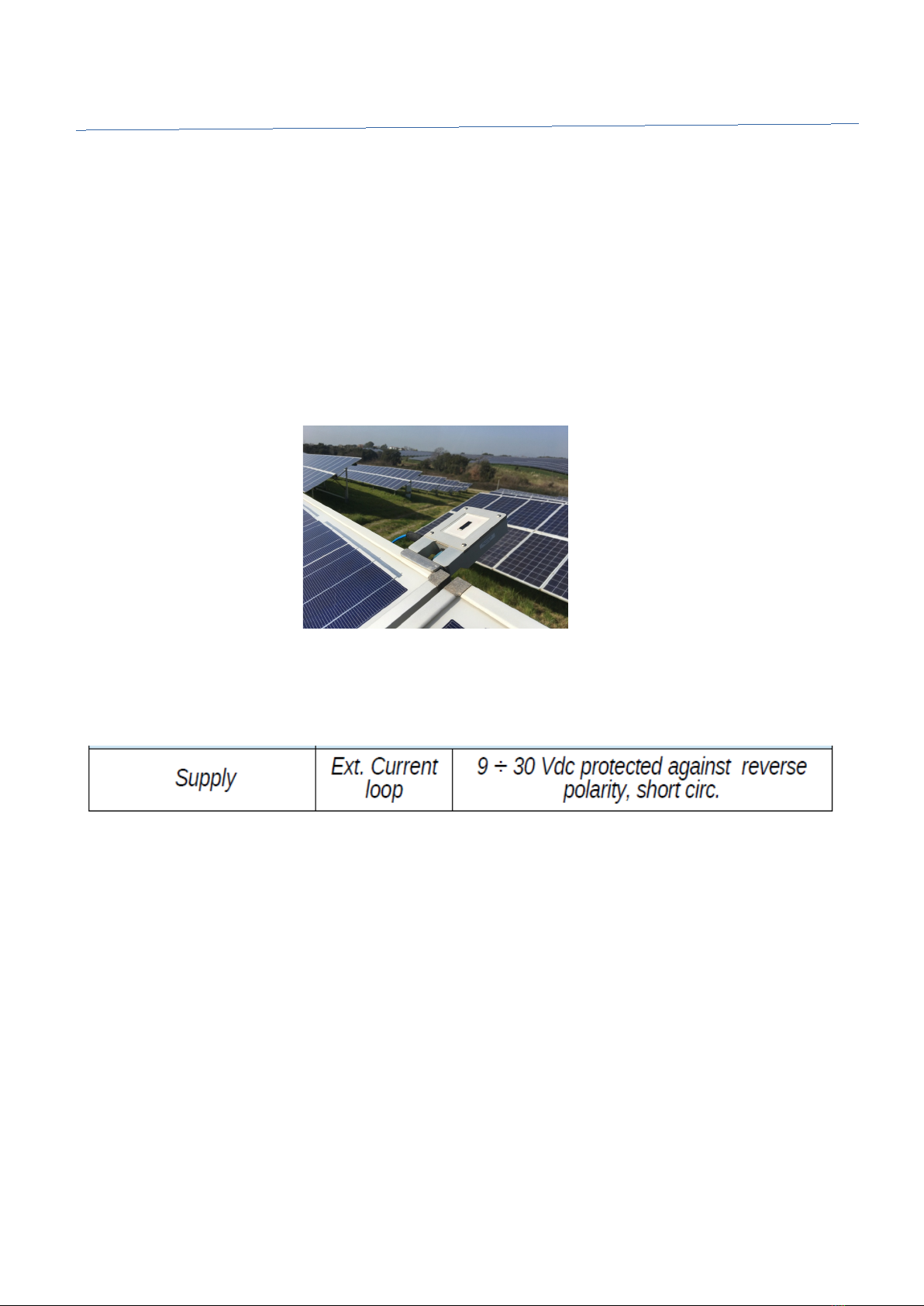
(4) Always clamp the Litemeter Pro sensor on parallel side of the PV module in order to avoid
casting of the shadow on the PV module behind it.
(5) Make sure the sensor is placed on the same plane and angle as of the PV module array for
optimal measurements.
3

1.Recommended to do during the installation- Electrical
1.2 Electrical
(1) For proper cable connections, please refer to the instruction manual that comes along with
the Litemeter Pro device and also you can find it in this following link:
(https://soluzionesolare.com/wp-content/uploads/2 22/12/Manu_LM5-485-PRO_22.pdf)
(2) Power supply should be connected with the exact pins as the manual indicates and the
suitable voltage to be supplied is 9-30 Vdc.
(3) For the connections, we suggest you to use twisted cables which are shielded.
(4) Always connect the shield to the ground.
(5) If there is no signal received from the RS485 port, try to swap the cables A and B and check
again if the signal is received.
4
1.Recommended to do during the installation- Firmware
1.3 irmware
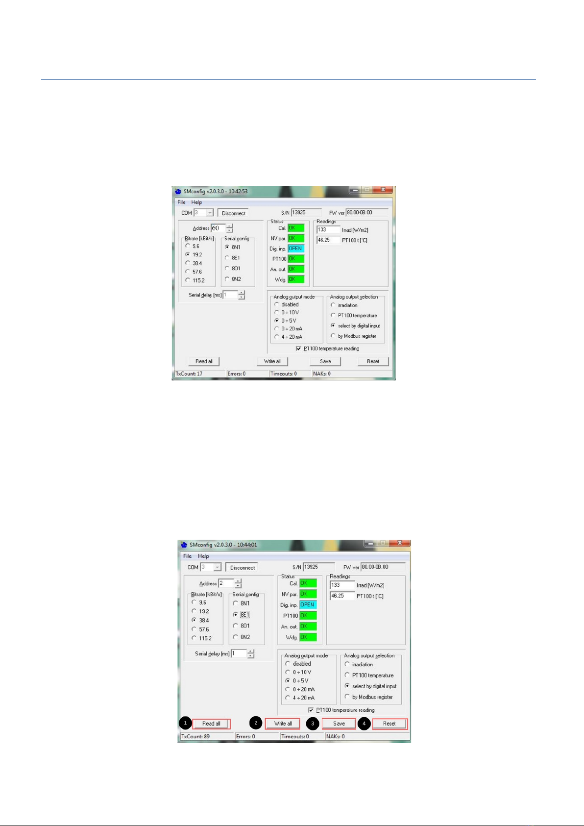
(1) For the first time after unboxing the Litemeter Pro, connect it using the default settings
(Address = 60,Baud rate =19200 and Serial configuration = 8N1).
(2) After turning on the Litemeter Pro, please wait for 5 seconds before connecting it to the SM
config software in order to achieve a proper configuration.
(3) In case, if you need to change the default settings value, use the SM config software by first
connecting the device with the default setting values mentioned in point 1 and then change
them to the required values.
(4) After changing the values click these buttons in the sequence as mentioned i)Read all
ii)Write all iii)Save and iv)Reset
5

1.Recommended to do during the installation- Firmware
(5) Please ensure you leave a time gap of 2 seconds in between clicking each buttons.
(6) We recommend you to place a label on the Litemeter Pro with the new settings in order to
remember the modified new settings.
(7) Bit rate should be set low in case of long wire connections and environment with more
electrical noises.
6
2.Not recommended to do during the installation
2. Not recommended to do during the installation
1. It is not recommended to connect the Litemeter Pro at the bottom side of the PV module,
since there will be casting of shadows on the sensor which could modify the readings and
also sensor could get affected in case of rain water flow. Always clamp the sensor on the
parallel side of the PV module in order to avoid casting of shadow on the PV module behind
it. Alternately in rare cases, Litemeter Pro sensor can be clamped on top of the PV module
when there is an optimal distance between the two rows of the PV modules.
2. o not supply voltage which is very low or very high from the recommended values
mentioned in the user manual.
3. o not let the PINs get exposed to water and humidity. It is recommended to use a sealed
box to place the wires in order to protect it from water and humidity.
4. o not bend the connectors or cables and it is not recommended to place it on sharp edges.
5. It is not recommended to use dusty sensors which could show a deviated readings. Always
clean the sensors for optimal readings.
7
3.MO BUS troubleshooting
3.MODBUS troubleshooting
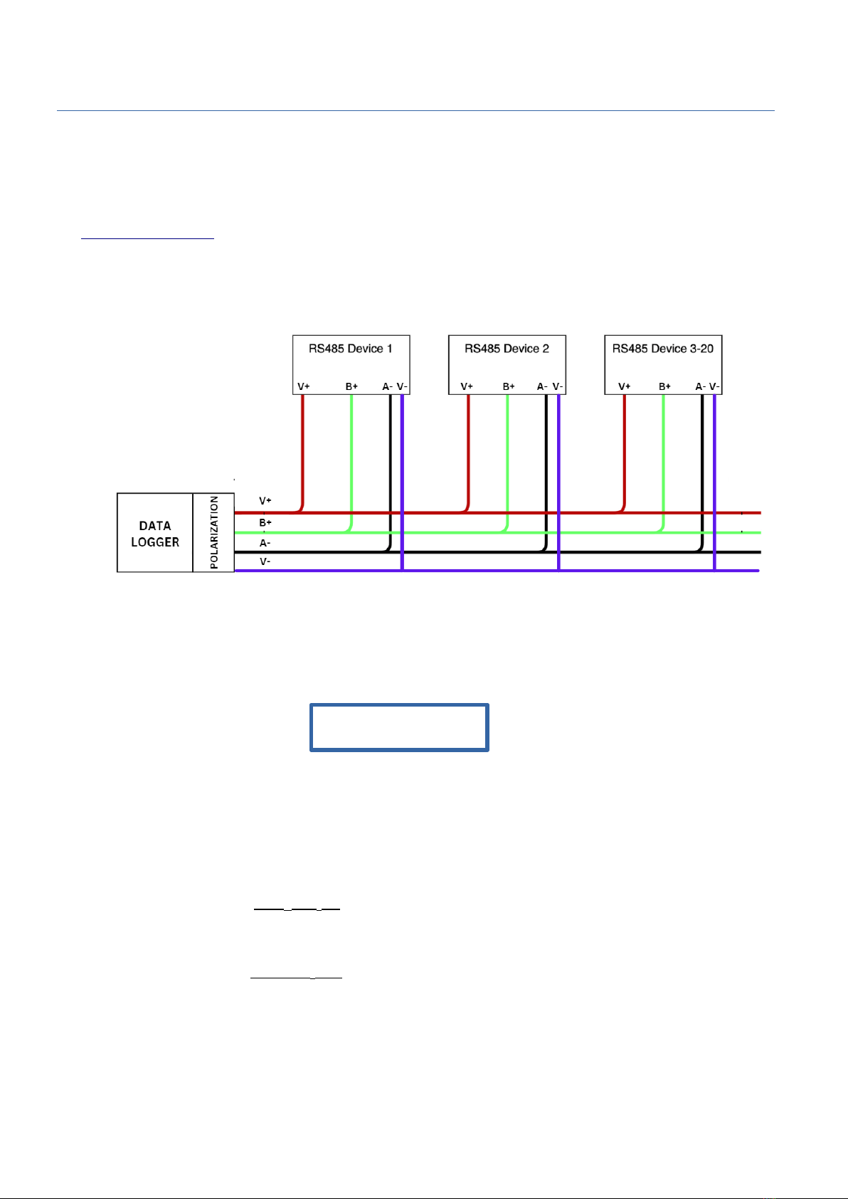
(1) For troubleshooting and information about MO BUS protocol kindly visit
https://modbus.org/ even for recommendations on polarization. Kindly check the general schema of
the MO BUS RS485 protocol given below.
In case if you have a bad communication and in order to have a right polarization, follow this
formula for calculating the voltages between B+ and A- for finding out if the connections satisfy the
condition
VB+ - VA- ≥ 0.2 V
Polarization network
If the above condition is not satisfied, please refer to the polarization network to be inserted on the
bus
Voltage in B+ is equal to (R2 + R3) * (V+)
(R1+ R2 + R3)
Voltage in A- is equal to ( R3) * (V+)
(R1+ R2 + R3)
Where R1, R2 and R3 are the three resistors.(refer to the example images)
V+ is the supply voltage
8

3.MO BUS troubleshooting
If the Datalogger does not have this RS485 net, the user has to do the proxy from
input/output.
If the lines are longer user could implement the polari ation and if the line is more longer
it is suggested to provide with a local power supply which should be polari ed.
Examples of local power supply for less than 5 devices connected is given below.
Example for 12V
Example for 24V
9
R1
R2
R3
R1
R2
R3
3.MO BUS troubleshooting
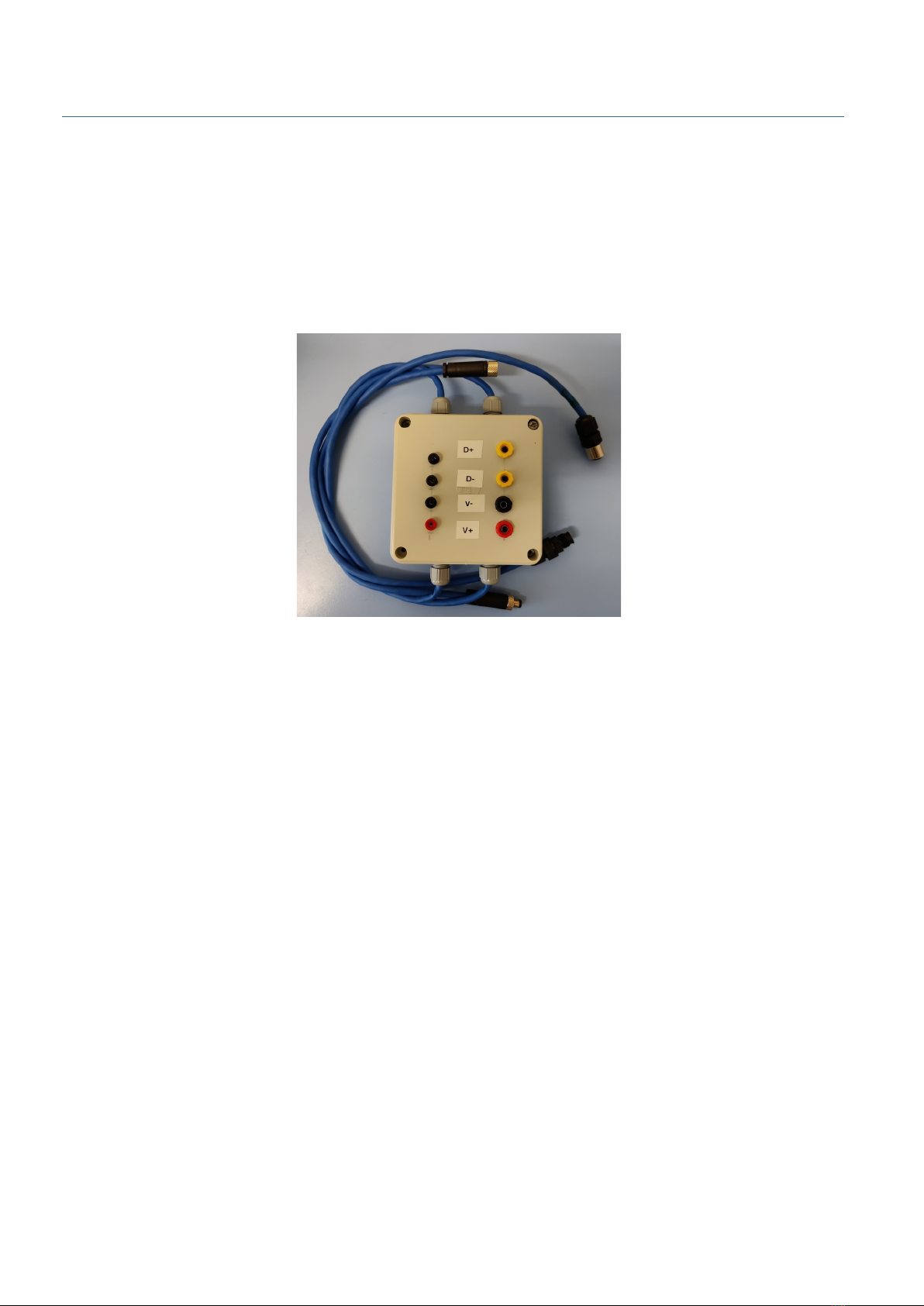
(4) If you have troubles with MO BUS connection which can happen if you have more than a
couple of devices from different manufacturers connected in the same RS485 line, it is suggested to
test the values along the RS485 cable. If you find it difficult to test the values along the line,
MO BUS test box can be used. Please check the output voltage levels and impedance of each
terminal using the MO BUS test box.
1

4.Contact and Customer support
Contact and Customer support
Soluzione Solare S.r.l.
Email: tecnico@solu ionesolare.it
Phone: +39 0444 530234
In case of technical support,
In the email please include the below mentioned information:
• Mention the evice model
• Mention the evice serial number
• Mention the information about the fault or problem
• Attach some pictures which represents the fault or problem
11
Table of contents


