ALFAMATIC Visual Point User manual

Sep. 26, 2019
Visual Point
Version with VP2STEP1 card
Installation manual

2

3
1 Introduction..................................................................................................................................4
1.1 Important notes for installation ...................................................................................................... 4
1.2 Dimensions ........................................................................................................................................ 5
2 Implementing VISUAL POINT...................................................................................................7
2.1 Operating of the instrument ............................................................................................................ 7
2.2 Information for connection to an external controller (PLC) ........................................................ 8
2.3 Wiring instructions........................................................................................................................... 9
2.4 Typical connection.......................................................................................................................... 14
2.5 Instructions for assembling the instrument with cabinet............................................................ 15
2.6 Switching on the instrument .......................................................................................................... 15
2.7 Aligning the encoder....................................................................................................................... 15
2.8 SETPOINT output.......................................................................................................................... 16
2.9 Work selection by inputs................................................................................................................ 16

4
1 Introduction
This manual describes the operations necessary to connect the machine to VISUAL POINT.
There are two versions of VISUAL POINT: for external mounting and for panel mounting.
The panel version is only available with 24VDC power.
The external mounting version is available in versions: 24VDC or 100-240VAC.
Before connecting the instrument, check carefully the supply voltage.
Picture 1
1.1 Important notes for installation
Read this notes, please:
Always check the supply voltage before proceeding with its wiring.
This instrument is not (and could not be) a safety device: the descent of the press must be
entrusted to elements outside the instrument. The instrument only synchronizes the
descent of the press in order for it to work.
It is very important for the load cell wire terminal, which is not sheathed, to be as short as
possible.
When the machine has electric motors, these must be equipped with an anti-interference
filter and be controlled using semiconductor devices.
Always connect the container of the instrument to the earth conductor.

5
1.2 Dimensions
All dimensions in millimeters.
Panel mounting
To the depth indicated, you have to add the
dimension of the teminal blocks and of cables whith
minimum lenght of 55mm
Hole dimensions:

6
External mounting
To the depth indicated, you have to add the
dimension of cables whith minimum lenght of
80mm

7
2 Implementing VISUAL POINT
The VISUAL POINT is divided into two sections with each other opto-isolated. The first section
features the control logic and electronics interface to transducers. The second section features the
electronics for digital inputs and outputs.
The two sections have separate power supplies, both at 24VDC.
Both sections can be supplied with a common power source.
The internal power supplier (Picture 2) allows the direct connection of the instrument to the net
electrical supply.
Tensions accepted range from 100VAC up to 240VAC both 50Hz and 60Hz.
Picture 2
2.1 Operating of the instrument
Attention: the VISUAL POINT is not (and could not be) a safety device: the descent of the press
must be entrusted to external elements. The VISUAL POINT synchronises the descent for its
operation. The GO Output is usually connected serially to the chain of the cylinder descent. In
short, if the CSQ-Visual activates the GO enabling output, the cylinder must not descend if it is not
safe
Operation takes place as follows: when the START input is activated by an external command, the
VISUAL POINT, if ready, activates the protection descent output (PROTECTION) where present
and enables the cylinder descent (GO). When the protection is closed, a safety device must activate
the cylinder until the VISUAL POINT removes the cylinder descent enabling signal (GO). The
VISUAL POINT then commands the arrest of the press, removing the GO signal, controls the
curve until the force begins to diminish or is activated by way of the T.D.C. input (withdraw
cylinder signal). Only then does it indicate whether or not the piece is good or a reject.
If the piece is good, the GOOD output is activated and the PROTECTION output, where present, is
deactivated. If the piece is a reject, the REJECTED output is activated intermittently and the
PROTECTION output, where present, is left active. When the operator presses the reset button,
which can be external or always active, the instrument maintains the REJECTED output as fixed
and removes the PROTECTION output.
The RESET input can be connected directly to +24 V and left always active, so that the instrument
is always ready to execute a new cycle.

8
The START input has to be held active throughout the cycle, otherwise the instrument
communicates "cycle interrupted" and the piece is rejected.
You can connect a sensor piece presence (ENABLE) that enables the start only when the
appropriate input is active. To use this signal is necessary to activate the option in the configuration
of the instrument.
The proper “setting to zero” of the encoder is done using the zero mark and the signal the press ram
is back to the TDC. The reset is executed by the instrument when the TDC switch is activated the
encoder goes through the zero notch. So for the proper zeroing it needs to be ensured the presence
of the zero mark in the interval where the TDC switch is active.
There is an exit SETPOINT that is activated when the starting point is measured or when you reach
a preset value (see paragraph 2.9).
The work (or recipe, or program) that the instrument must use, can be selected with some inputs:
see Chapter 2.10. The work selected changes every time you change the input selection status.
After the start signal, the work selected is maintained until the end of the cycle.
2.2 Information for connection to an external controller (PLC)
To connect the VISUAL POINT to a PLC, the latter must have PNP positive logic. The inputs and
outputs of the instrument are opto-isolated from the instrument’s control electronics. The power
supply of the instrument’s inputs and outputs must be the same that powers the inputs and outputs
of the PLC. We recommend the use of at least one output (START signal) and three inputs of the
PLC (GO, GOOD and REJECTED). If necessary, with the press controlled directly by the
instrument, it is possible to use a single input to know whether the piece is good (GOOD output)
and a single output to control the start of the pressing cycle (START input).
Remember that, in all cases, it is always necessary too connect the T.D.C. input of the VISUAL
POINT. The T.D.C. signal can be acquired directly by a limit switch activated with the press in the
resting position. However, the signal indicating that the press is in the resting position is almost
always used by the PLC. In this case the signal to be given to the instrument may be taken parallel
to that delivered to the PLC.

9
2.3 Wiring instructions
The VISUAL POINT features several input and output options.
As inputs: load cell, position transducer and command signals.
As outputs: signals for controlling the valve that enables the descent of the press ram, the valve for
closing the safety guard and protection flags.
The input signals can be: simple contact or 24Vdc positive logic, with PNP transistor output.
The outputs of VISUAL POINT, when activated, provide a voltage of 24Vdc. The maximum load
of each output is 15 watts. For higher loads is necessary to use relays support. The total maximum
load supported by the instrument, when equipped with the internal power supplier, is 50 watts.
The wiring is supported by removable terminal blocks (X3, X4...). Every terminal on every
terminal block is numbered (Errore. L'origine riferimento non è stata trovata.). For example,
when terminal X4.7 is indicated, reference is made to the seventh terminal of terminal block X4.
The numbers are also printed on the printed circuit of the card.
2.3.1 Main power terminal block (X1)
The electronics of the VISUAL POINT and the transducers are powered at 24VDC via the X1
three-pole terminal block.
Name Function Terminal
0VDC Negative power X1.1
PE Earth connection
X1.2
+24VDC
Positive power X1.3
If the internal power feeder is fitted, the switch behind the instrument has to interrupt the phase and
neutral before reaching the power feeder. The power feeder output must be connected to terminal
block X1.
This terminal is not feeding the input and output section, which is separated by opto-isolators from
the electronics of the instrument. To feed the section of input and output, connect to the power
supplier the terminal blocks X3.11 and X3.12.
2.3.2 Serial port terminal (CONN1)
Only present in version with cabinet for external mounting.
On the back of the VISUAL POINT is a D-Sub 9-male for the RS232 serial connection. The
connector pin-out is as follows:
Pin 2: RX input line of Visual Point.
Pin 3: TX output line from Visual Point.
Pin 5: GND Mass signals

10
2.3.3 Serial Port terminal (X2)
Only present in version for panel mounting.
On the back of VISUAL POINT for panel mounting is the X9 terminal block to connect serial
RS232. The connector pin-out is as follows:
Name Terminal Function
X9.1 Do not use
TX X9.2 Output – signal toward the computer RX, connect to pin nr 2 of the male D-SUB 9
connector on the PC
RX X9.3 Input – signal coming from computer TX, connect to pin nr 3 of male connector DSUB 9
of PC
A+ X9.4 RS485 A+
B- X9.5 RS485 B-
0V X9.6 Signal ground, connect to nr. 5 pin connector D-SUB 9 male of computer
2.3.4 Inputs terminal block (X3)
The inputs are optoinsulated and compatible with clean contact signals or 24 VDC PNP transistor
outputs.
Name Function Terminal Note
IN0 START X3.1
IN1 T.D.C. X3.2
IN2 RESET
RED BASKET
X3.3
IN3 ENABLE
JOB SELECTOR E
X3.4
IN4 EMERGENCE OK
JOB SELECTOR D
X3.5
IN5 GREEN BASKET
JOB SELECTOR C
X3.6
IN6 JOB SELECTOR B X3.7
IN7 JOB SELECTOR A X3.8
IN8 Do not use X3.9 Do not use
IN9 Do not use X3.10 Do not use
0VP Power I/O ports X3.11 Negative power supply for inputs and outputs
+24P Power I/O ports X3.12 Positive power supply for inputs and outputs
Maximum current of each input 10 mA

11
Input functions:
Function Description
START Request for new cycle start
T.D.C. “Top dead point” signal, used to reset for a new cycle and in AND with the zero notch
of the encoder for the zero of the absolute positions
RESET Re-enables the instrument after a reject (rejects basket)
ENABLE Start enable
EMERGENCE OK Safety device OK
JOB SELECTOR Work selection
RED BASKET Bad pieces basket sensor
GREEN BASKET Good pieces basket sensor
2.3.5 Outputs terminal block (X4)
Outputs for 24VDC loads. For inductive loads such as valves and relays, it is necessary to have a
diode parallel to the coils to eliminate peaks in voltage.
Name Function Terminal Note
OUT0 GOOD X4.1
OUT1 REJECTED X4.2
OUT2 GO X4.3
OUT3 PROTECTION
BUZZER
X4.4
OUT4 CONTACT/BOOSTER
SETPOINT
PULLUP
X4.5
OUT5 TANK
RETURN
X4.6
OUT6 X4.7
OUT7 X4.8
NU X4.9 Do not use
0VP Power outlet X4.10 This terminal can be used as the return of the utilities connected
to the outputs. It is connected internally to terminal X3.11.
Nominal current of each output 1 A

12
Output functions:
Function Description
GOOD Good piece signal. Active after the return of the cylinder until the next start.
REJECTED Rejected piece signal. Active after the return of the cylinder until the next start. The
output is intermittent until the reset signal.
GO Enables the press. Active after the start if the instrument is ready and deactivated
upon reaching the stoppage value.
PROTECTION Command for the closure of the protection.
BUZZER Command for acoustic signal.
CONTACT/BOOSTER Conctact signal or start work stroke signal.
SETPOINT Force or position trigger. See Chapter 2.8
PULLUP Command for return cylinder.
TANK Segnale chiusura serbatoio del cilindro Alfamatic tipo PK
RETURN Enable return of cyinder
2.3.6 Encoder and 0-10V input terminal block (X12)
An incremental encoder and a 0-10V signal can be connected to the X12 terminal block. A 12VDC
power supply is available for the encoder. A very high-precision 10VDC power supply is available
for the potentiometer.
Name Terminal Function
Phase Z X12.1 Encoder zero signal
Phase B X12.2 Encoder phase B signal
Phase A X12.3 Encoder phase A signal
+12V X12.4 12 V encoder power (200mA max)
0V X12.5 Screened wire sheath
0V X12.6 0V of the encoder and potentiometer
+10V X12.7 10 V potentiometer power (10mA max)
POT X12.8 0-10V input.
Electrical features of terminals X12.1, X12.2 and X12.3
2.3.7 Load cell terminal block (X6)
Input for load cell with resistive jumper with a sensitivity of 2mV/V. The power for supply the load
cell is also available on this terminal block.

13
Name Terminal Function
IN+ X11.1 Positive input
IN- X11.2 Negative input
0VL X11.3 Screened wire sheath
0V X11.4 0V
+10V X11.5 Power (60mA max)
It is extremely important for the end of the wire of the load cell which is not covered by a
sheath to be as short as possible.
2.3.8 Analog output terminal block (X10)
Name Terminal Function
NU X10.1 Do not use
NU X10.2 Do not use
NU X10.3 Do not use
NU X10.4 Do not use
NU X10.5 Do not use
NU X10.6 Do not use
NU X10.7 Do not use
0V X10.8 REF analog outputs
ANA1 X10.9 0-10V output 1
ANA2 X10.10 0-10V output 2

14
2.4 Typical connection
Wiring an encoder ELCIS and a load cell AEP:
picture 3

15
2.5 Instructions for assembling the instrument with cabinet
picture 4
To open the container with VISUAL POINT unscrew the four screws in the corners of the back and
front panel.
Dismantle the groups of terminal blocks.
Pull out the electronic boards from the front (Figure 10).
Mount the cable and plugs needed (Pg 9).
Put the wires in the cable and start wiring as the wiring diagram.
To know the number of groups of terminal blocks, you can look at the Figure 5.
After the wiring insert the card.
Insert the terminal groups respecting their length and their sense of inclusion.
2.6 Switching on the instrument
After the wiring is possible to feed the tool and follow the following steps:
Turn on the instrument. The display lights up.
Go to the menu Configurazione > Information > Show advanced settings.
Go to the menu Configurazione > Machine and activate the right options (see user manual).
Proceed with the calibration of the instrument (see user manual).
Verify that the sensors and related utilities, are working properly, through the Diagnostics
menu (see user manual).
2.7 Aligning the encoder
If it is replaced or if the encoder is shifted TDC is necessary to reposition the way the encoder. To
do that, there is a clear share of the offset as described in the user manual to see and follow the
instructions below.
2.7.1 For standard presses Alfamatic
First press the mushroom emergency press, turn on the instrument and open the top cover of the
rack lock, which is closed by two self-tapping screws with head a cross. Inside you can see the
pinion the encoder. Unscrew the two screws that secure the encoder and move upwards in this way,
the display of the instrument will change the share that at some point, will come to zero. This is the
exact position of the rear of the encoder zero. Move now the encoder of about one inch at the
bottom so that the display indicates -1 mm. Pulling back the encoder is able to release the pinion by
the rack, so you can set the encoder to its original position without the change the quota. In practice
you should be able to fix the encoder and see how to share a value between -3 and -1 mm.
To verify the correct positioning, turn off and on the instrument at this point, the share should be

16
zero. Starting the press and make it back to the TDC: At this point the tool has a negative view of a
few millimeters.
2.8 SETPOINT output
The VISUAL POINT SETPOINT has an exit which is normally activated when the share is
measured starting (see user manual) and is off when the value of arrest. This can be used to start the
phase of work, after the phase approach.
Changing the configuration can be done so that the output SETPOINT be activated when you reach
a strength or a set.
Always changing the configuration can be done so that the output SETPOINT not be turned off to
the arrest of the cylinder, but only when the press is completely backwards session (TDC active
input) and, with the scrap piece, not because of the reset . In practice, this configuration allows you
to connect to the SETPOINT a decelerator or force that keeps the piece into place.
Notes:
SETPOINT output is activated only when the input TDC is not active.
The exit is on SETPOINT without signal START.
2.9 Work selection by inputs
The VISUAL POINT supports the automatic selection of work using the combination of the inputs.
This selection can be useful for automatically recognising the piece or the tool fitted.
The work number is obtained from the binary combination of the inputs. The binary code of the
first work is zero, i.e.: no input active. The maximum number of selectable works, if enough inputs
are available, is 16 (with binary codes from 0 to 15).
The wiring is connected to a terminal block inside the instrument marked X3.
The highest inputs must be used for selection.
The sensors are connected to the inputs WORKSEL reported in paragraph 2.3.2. The entrance
WORKSEL A is the least significant.
After the wiring it it necessary to instruct the instrument on how many works can be selected; to do
this you must change the configuration value.
Other manuals for Visual Point
1
Table of contents
Other ALFAMATIC Measuring Instrument manuals
ALFAMATIC
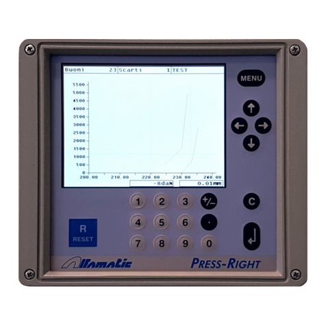
ALFAMATIC Press-Right User manual

ALFAMATIC
ALFAMATIC Press-Right User manual

ALFAMATIC
ALFAMATIC CSQ-Visual User manual

ALFAMATIC
ALFAMATIC PRESS -RIGHT User manual

ALFAMATIC
ALFAMATIC Press-Right User manual

ALFAMATIC
ALFAMATIC Press-Right User manual

ALFAMATIC
ALFAMATIC CSQ-Visual User manual

ALFAMATIC
ALFAMATIC CSQVIO8 User manual
Popular Measuring Instrument manuals by other brands

Endress+Hauser
Endress+Hauser Prosonic M FMU40 operating instructions

ALPA
ALPA MEGAtower Use and maintenance manual

ATIM
ATIM Cloud Wireless ACW/SF8-LVL user guide

Fema Electronica
Fema Electronica S Series user manual

Seneca
Seneca S203TA-D user manual

Gossen MetraWatt
Gossen MetraWatt lunasix Operating instructions manual