Solwise L201 Instructions for use

2
T
a
b
l
eo
f
C
on
t
en
t
s
T
A
B
L
E
O
F
C
O
NTEN
TS
2
I
N
T
R
O
D
U
CE
3
I
N
ST
ALL
I
N
G
V
O
I
C
E
B
R
O
A
D
B
A
N
D
G
A
TE
W
AY
3
1.
C
ONNECT
I
NG
THE
P
OWER
A
DA
P
TER
3
2.
C
ONNECT
I
NG
TO
A
PC
3
3. C
ONNECTING TO A
D
SL
/C
ABLE
M
ODEM
3
4.
SETTING
U
P A
M
ANAGEMENT
PC
3
C
O
N
F
I
GU
R
I
NG
T
H
E
V
O
I
C
E
B
R
O
A
D
B
A
N
D
G
A
TE
W
AY
4
1 C
ONNECTING TO THE
W
EB
C
ONFIGURATOR VIA A
W
EB
B
ROWSER
4
2.
SETUP
W
IZARD FOR
Q
UICK START
:
5
2.1 WAN S
ETUP
: (
REQUIRED FOR
I
NTERNET ACCESS
) : 5
2.2 DHCP S
ETTING
: 5
2.3
F
IXED
IP S
ETTING
:
5
2.4
PPP
O
ES
ETTING
:
6
2.5 N
AT S
ETUP
:
6
2.6
V
O
IP
C
ALL
S
ETUP
:
7
S
C
EN
A
R
I
O
AP
P
L
I
C
A
T
I
ON
9
A
PP
EN
D
IX
9
D
IRECT CALL
(P
EER TO PEER
)
SETUP
9

33
I
n
tr
o
d
u
ction
This manual is teaching you how to quick install and setup your gateway. If you
want to know more detail information about this gateway, please see the user
manual.
Getting started with Web browser for VoIP Gateway involves the following
general procedures:
Installing VoIP Gateway
Configuring VoIP Gateway
Scenario Application
I
n
s
ta
ll
i
n
g
V
o
i
c
e
B
r
o
ad
b
and
G
at
e
w
a
y
1.
Conn
ec
t
i
ng
t
h
e
P
owe
r
A
d
a
p
t
er
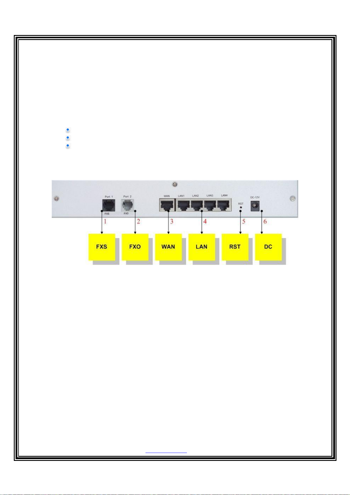
1.1 Connect the power adapter to the power outlet and to the PWR power jack on the rear
panel of the Gateway.
2.2 The Power LED should be lighting.
2.
Connecting to a PC
2.1 Using an Ethernet cable to the LAN 1 port or to anyLAN1 ~ LAN4 port.
2.2 Connect the other end of the Ethernet cable to your PC’s installed network interface card
(NIC).
2.3 The LED indicators at both the Ethernet port and the NIC should be ON.
3. Connecting to a DSL/Cable Modem
The VoIP Broadband Gateway supports connection of a DSL modem via an Ethernet
interface.
3.1 Locate your Ethernet cable (should be provided by your ISP or telecom).The hardware
installation is now complete.
3.2 Using a Ethernet cable to the Ethernet port of the DSL/Cable modem.
3.3 Plug the other end of the cable into the WAN port of Gateway.
4. Setting Up a Management PC
The Gateway has a built-in HTTP (Web) server for configuration. Before you use the
Gateway to access the Internet, you should set up a management PC to log into the
Gateway for further configuration by connecting to LAN port. The management PC may be
configured with a fixed IP address.
For a fixed IP address, use an IP address from a 222.222.222.xnetwork, such as
222.222.222.2.Or use DHCP form Lan port of gateway.

4
C
on
f
i
g
ur
i
n
g
t
he
V
o
i
c
e
B
r
o
adband
G
at
e
w
a
y
1 Connecting to the Web Configurator via a Web Browser
1. Launch the Web browser. Enter http://222.222.222.1 into the browser Address window
and press the Enter key.
2. An authentication dialog boxwill open.
3. If this is a first time setup of the Gateway, type admin as the User Name and admin as the
Password field. Click OK.
4. The Web Configurator Setup Main Menu will open as below :

5
5. Please Click on “Setup Wizard” to enter Quick Start procedure:
2. Setup Wizard for Quick Start :
This Wizard will take you to complete the Basic Setting step by step:
2.1
W
AN Se
t
up
:
(
r
e
qu
i
r
e
d
fo
r
I
n
t
e
r
n
e
t
a
ccess)
:
You could select one of three WAN types for access internet.
2.2 DHCP Setting :
While you click on “DHCP – Cable Modem”, you enable DHCPClient. Please Click on “Next “,
then you enter the “NAT Setting” (Please go to 2.5 NAT Setting)
2.3 Fixed IP Setting :
When you select “Fixed IP“ option, you could see the Fixed IP setting menu to key in “IP address”,
“Default Router IP Address” and “Subnet Mask”. Please Click on “Next “, then you enter the “NAT
Setting” (Please go to 2.5 NAT Setting)

6
2.4 PPPoE Setting:
When you select “PPPoE - ADSL“ option, you could see the PPPoE setting menu. Please filled in
Username and Password gotten from (Internet Service Provider) ISP. Please Click on “Next “,
then you enter the “NAT Setting” (Please go to 2.5 NAT Setting)
2.5 NAT Setup:
2.5.1 After completing the WAN Type Setting , you would enter
“
NAT Setting
”
menu. VoIP Broadband
Gateway Provide two modes, one is Bridge Mode, the other one is NAT Mode:
2.5.2 Setting LAN IP address to provide a C-class subnet
2.5.3
Please Click on “Next “, then you enter the “NAT Setting” (Please go to 2.6 VoIP Call Setup)

7
2.6 VoIP Call Setup:
VoIP Setup menu provide user a Basic Function Setting
When you use H.323 Protocol:
1 Port Setting : Configuring the port number. The maximum characters is 20
2 Register Gatekeeper: You need key in
“
Gatekeeper IP address
”
for Gateway to register if needing.
3. Direct Call Plan Setting: if you don
’
t register Gatekeeper and want to use Peer to Peer call, you must
setting the dial plan. When you use the peer to peer mode, please setting the gatekeeper field to
“
0.0.0.0
”
.
(About Dial plan setting, please see the Appendix Dialing Plan.)

8
When you use the SIP protocol:
1 Port Setting : Configuring the port number. The maximum characters is 20
2 Register SIP Proxy Server: You need key in
“
SIP Proxy Server IP address
”
for Gateway to register if
needing.
3. Direct Call Plan Setting: if you don
’
t register SIP Proxy Server and want to use Peer to Peer call, you must
setting the dial plan. When you use the peer to peer mode, please setting the SIP Proxy Server IP field to
“
0.0.0.0
”
. (About Dial plan setting, please see the Appendix Dialing Plan.)

9
S
c
en
ar
i
o
Ap
p
l
i
c
at
i
on
A
pp
en
d
ix
Direct call (Peer to Peer) setup
If you don’t registered Gatekeeper or SIP proxy server, you can make call by Peer to Peer. For
SIP or H.323, setting the dialing plan, and can make direct call.
Overview of the Dialing Plan
The “Dialing plan” need setting when the user use the method of Peer-to-Peer H.323 (SIP)
VoIP call or registering H.323 Gatekeeper (SIP Proxy Server) Mode. The H.323(SIP) Dialing Plan
has two kinds of directions: Outgoing (call out) and Incoming (call in).
1. Outgoing Dial Plan:
Peer-to-Peer Call Mode: Effective
Registering to H.323 Gatekeeper (SIP Proxy Server) Mode: Effective

10
2. Incoming Dial Plan:
Peer-to-Peer Call Mode: Effective
Registering to H.323 Gatekeeper (SIP Proxy Server) Mode:
The leading number would register to H.323 Gatekeeper (SIP Proxy Server)
When you use direct call, you must setting your VoIP protocol firstly. Use direct call, you should
setting the same protocol both of UA. Both of UA must support dial plan function. Some ATA don’t
support Dialing plan, it maybe let direct call failed.
In the “Outgoing Dial Plan Configurations” settings: Maximum Entries : 50
“Outbound number” is the leading digits of the call out dialing number.
“Length of Number” has two text fields need filled: “Min Length” and “Max Length” is the
min/max allowed length you can dial.
“Delete Length” is the number of digits that will be stripped from beginning of the dialed
number.
“Add Digit Number” is the digits that will be added to the beginning of the dialed number.
“Destination IP Address / Domain Name” is the IP address / Domain Name of the
destination Gateway that owns this phone number.
“Destination Port” is port of the destination gateway use.(Default is 5060)
Example1: Normally Dial
1.001x leading call out, call to Destination IP address: 211.22.3.14
2.002x leading call out, call to Destination Domain Name: h.323.gw.net

11
Example2: Speed Dial
1. If user dial “401”,
Gateway automatically dial “1334588712” to Destination IP address: 211.22.3.14
2. If user dial “402”,
Gateway automatically dial “2212345612” to Destination IP address: 211.21.2.76
In the “Incoming Dial Plan Configurations” settings: Maximum Entries : 50
“Inbound number” is the leading digits of the dialing number.
“Length of Number“ has two text fields need filled: “Min Length” and “Max Length” is the
min/max allowed length you can dial.
“Delete Length” is the number of digits that will be stripped from beginning of the dialed
number.
“Add Digit Number” is the digits that will be added to the beginning of the dialed number.
“Destination Tele port” is “Tel-port”; this is for local dial plan setting phone number.
Example1: Hunting for FXS Port
Port 1: FXS
Port 2: FXS
Port 3: FXS
Port 4: FXS
H.323 (SIP) number “123”call incoming, Port 1 will be ringing.
If Port 1 is busy, Port will be ringing.
If Port 1 and 2 are busy, Port 3 will be ringing.
If Port 1, Port 2 and Port 3 are busy, Port 4 will be ringing.

12
Example2: Hunting for FXO Port
Port 1: FXO was connected to PSTN.
Port 2: FXO was connected to PSTN.
Port 3: FXO was connected to PSTN.
Port 4: FXO was connected to PSTN.
H.323 (SIP) number “123”call incoming, Port 1 will be off-hook and hear the Dial Tone from
PSTN.
If Port 1 is busy, Port will be will be off-hook and hear the DialTone from PSTN.
If Port 1 and 2 are busy, Port 3 will be off-hook and hear the Dial Tone from PSTN.
If Port 1, Port 2 and Port 3 are busy, Port 4 will be off-hook and hear the Dial Tone from
PSTN.
Example3: Termination Call to FXO for One-Shoot Call
Port 1: FXO was connected to PSTN (area code is 81xxxxxxxx).
H.323 (SIP) leading number “081x”incoming, and delete the first one digit “0”, and call to
PSTN number.
Example4: Termination Call to FXO
Port 1: FXS
Port 1: FXO was connected to PSTN (area code is 92xxxxxxxx).
Port 1 FXS call to “092x” to PSTN, FXO port will delete the first one digit “0” and call to
PSTN number.
( [x]: mean wild card, 0~9.Speed dial: When you dial over the number, input “#” keycan speed dial
call, or you key in number as the length as the “length of number” )
Table of contents
Other Solwise Gateway manuals
Popular Gateway manuals by other brands

ABB
ABB 3AUA0000235813 user manual

ZyXEL Communications
ZyXEL Communications ZyXEL Vantage VSG-1000 Specifications

Emerson
Emerson 1410S Reference manual

Enterasys
Enterasys Aurorean ANG-7000 Series Application note

THOMSON
THOMSON SpeedTouch 580 Installation and setup guide

Rath
Rath 2100-LTEGSM4 Installation & operation manual