Sonardyne 6G ROVNAV 6 User manual
QUICK START GUIDE
TYPE 8300 TRANSPONDERS
FIRMWARE UPGRADE GUIDE
To access more
information on the
firmware, download a
free QR code app on
your Smartphone and
then scan this code.
QSG-UP-8300-00-A0
11/2011
910-0001

SAFETY
It is recommended the operator complies with the Health and Safety Regulations applicable to
the vessel and the region before operating any equipment.
PRODUCT SUPPORT
Email: [email protected]
Tel: +44 (0) 1252 872288
Should you require NON-EMERGENCY product support for your firmware upgrade, email and
telephone product support is available during normal UK office hours (08:00-17:00 GMT).
Alternatively, please contact your nearest Sonardyne Office. Visit www.sonardyne.com for full
details.
In emergency situations, the Sonardyne 24 hour helpline is answered during normal office
hours - 08:00-17:00 GMT. Outside these hours, your call is automatically transferred to an
agency who will log the details of your emergency and alert the appropriate Sonardyne
personnel. Our aim is to ensure that emergency requests are dealt with immediately during
office hours and are responded to within 30 minutes at all other times.
SONARDYNE 24HR EMERGENCY HELPLINE: UK +44 (0) 1252 877600
To make sure the equipment operates correctly, make sure the correct firmware
is being installed.
Do not use the test cables to lift the equipment.
CAUTIONS
STEP 1
Make sure the equipment is clean and dry before removing the connection point
cover and connecting any test cables.
WARNING

EQUIPMENT SUPPLIED
STEP 2
This Quick Start Guide gives instruction on how to upgrade the HOST or DAS firmware
used in Type 8300 Transponders, using the Dual Test Lead.
The table below lists all transponders this Quick Start Guide is relevant to and their
identifying colour band.
To enable the firmware upgrade process, a Dual Test Lead is supplied with the equipment.
If the correct test lead is not available, please contact Sonardyne for product support.
Refer to Step 1 for details.
2NOTE
This Quick Start Guide is for the upgrade of the 8300 Series Transponders, for
the upgrade of the 8300 Transceivers (Dunker 6 and RovNav 6) please refer to
the 8300 Transceiver Quick Start Guide - QSG-UP-8300-01 A0.
Transponder Number Transponder Type Colour Band
8300
8301
8305
8307
8308
Compatt 6
DPT(i)6
AMT
Modem
SLT
Make sure all Warnings and Caution labels on the equipment are read and
understood. Refer to the equipment manual for further information and assistance.
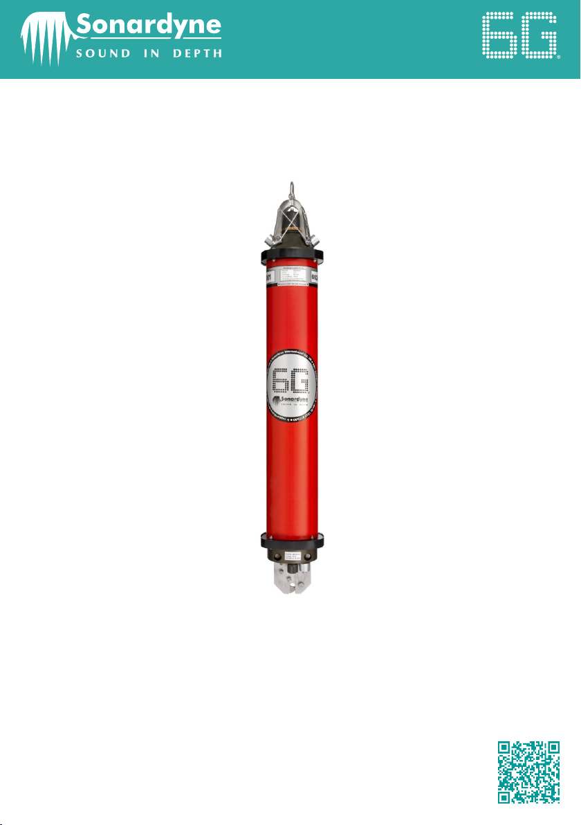
CONNECTING THE EQUIPMENT
STEP 3
1 Use the following instructions to connect the Dual Serial Cable to the Transponder.
2 Locate the round Dual Serial Cable connection point on the Transponder.
3 Using the special tool, remove the protective cover from the Dual Serial Cable
connection point .
1
1
2
3
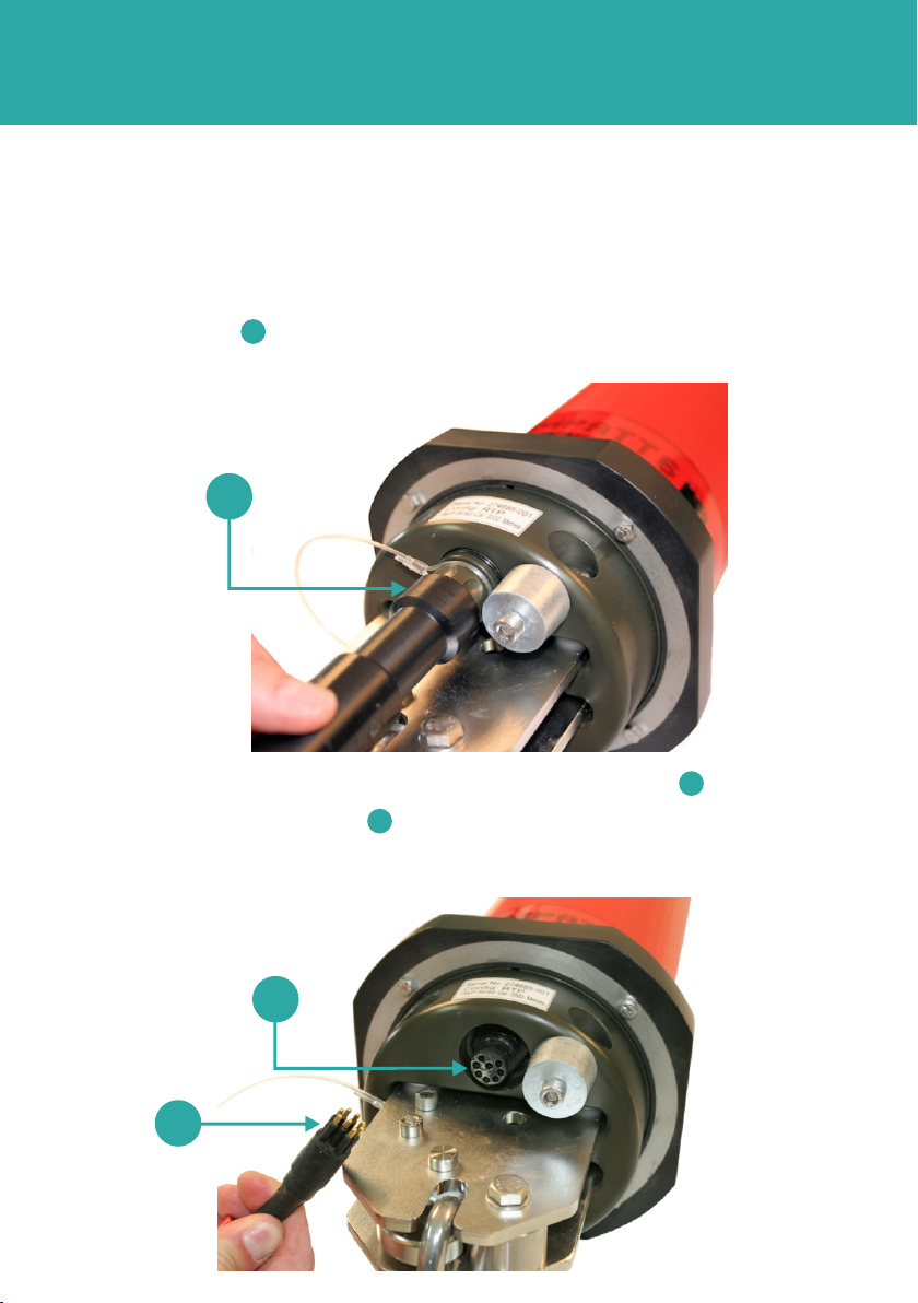
4 Check the connection points are free from obstructions and dirt .
5 Position the Dual Serial Cable in the correct orientation and insert into the
connection point.
2
3
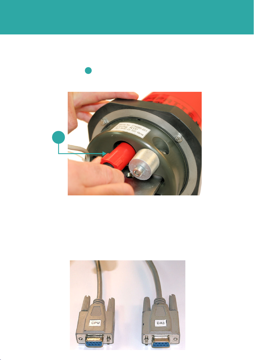
STEP 4
CONNECTING THE EQUIPMENT
7 The other end of the Dual Serial Cable has the CPU and DAS connectors for use
when requested in the instructions.
6 Make sure the Dual Serial Cable is inserted fully, and secure in place by screwing in
the red protective cover clockwise.
1
1
Other manuals for 6G ROVNAV 6
1
This manual suits for next models
1
Table of contents
Other Sonardyne Marine Radio manuals


