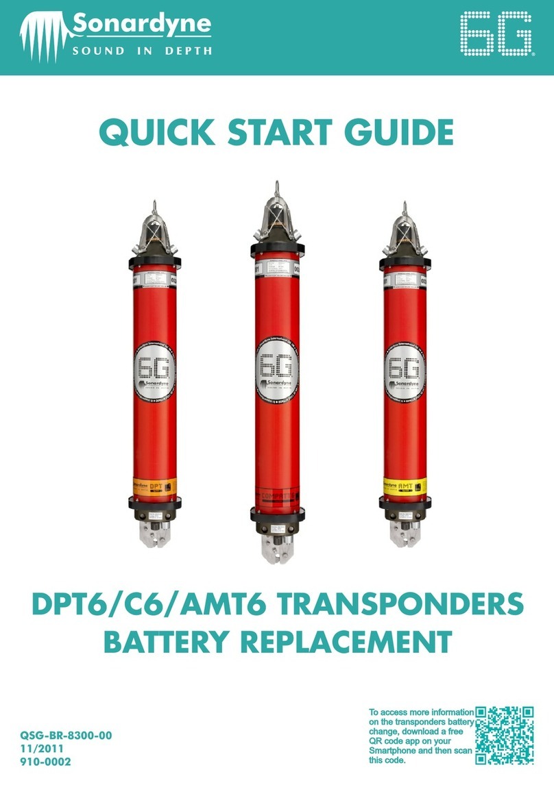
Sonardyne 8270 User manual

Head Office
Sonardyne International Limited
Blackbushe Business Park
Yateley, Hampshire
GU46 6GD United Kingdom
T. +44 (0) 1252 872288
F. +44 (0) 1252 876100
W. www.sonardyne.com
USER MANUAL 8270-000
Wideband Sub-Mini Transponder /
Responder (WSM6)
Type 8270 Directional and
Type 8271 Omni-Directional
Issue: A Rev 0
Date of issue: October 2011

WSM6 Manual
Document Ref: UM-8270-000
Issue: A Rev 0
ii October 2011
Copyright 2011 Sonardyne International Limited.
Sonardyne Wideband ® and 6 Generation® are registered trademarks.
All rights reserved. No part of this document shall be reproduced, stored in a retrieval system or
transmitted by any means, electronic, mechanical, photocopying, recording, or otherwise, or
translated into any language without the written permission of Sonardyne International Limited.

WSM6 Manual Document Ref: UM-8270-000
Issue: A Rev 0
October 2011 iii
CONTACTING THE SONARDYNE SUPPORT TEAM
24-hour Emergency Telephone Helpline: +44 (0) 1252 877600
The Sonardyne 24-hour helpline is answered during normal office hours (08:00 to 17:00 GMT).
Outside these hours, your call is automatically transferred to an agency, which logs the details of
your emergency and alerts the appropriate Sonardyne personnel.
Our aim is to make sure emergency requests are dealt with immediately during office hours, and
are responded to within 30 minutes at all other times.
Please note the helpline is for emergency use only.
If you require NON-EMERGENCY product support, please contact your nearest Sonardyne office.
Alternatively, contact the Sonardyne Head Office:
Blackbushe Business Park
Yateley
Hampshire
GU46 6GD
England
Telephone: +44 (0) 1252 872288
Fax: +44 (0) 1252 876100
Email: [email protected]
NOTE
Email and telephone support is available during normal office hours (08:00 to 17:00
GMT)

WSM6 Manual
Document Ref: UM-8270-000
Issue: A Rev 0
iv October 2011
This page is intentionally left blank

WSM6 Manual
Document Ref: UM-8270-000
Issue: A Rev 0
vOctober 2011
CONTENTS
Contacting the Sonardyne Support Team ....................................................................................iii
Contents ........................................................................................................................................v
Figures .......................................................................................................................................ix
Tables .......................................................................................................................................xi
Amendment History......................................................................................................................xiii
Section 1 – Introduction ..................................................................................................................1
1. Introduction.............................................................................................................................1
1.1 Related Publications........................................................................................................1
Section 2 – Safety ............................................................................................................................3
2. Introduction.............................................................................................................................3
2.1 Procedures ......................................................................................................................3
Section 3 – Technical description ..................................................................................................5
3. Introduction.............................................................................................................................5
3.1 Description ......................................................................................................................5
3.2 WSM6 .........................................................................................................................10
3.3 Configuration .................................................................................................................16
3.4 Battery Charging Description ........................................................................................17
3.4.1 Fast Charging.......................................................................................................18
3.4.2 Compatibility with SSM Chargers.........................................................................19
3.5 Variants .........................................................................................................................19
3.5.1 8270-000-11 WSM6 .............................................................................................19
3.5.2 8270-000-07 WSM6 .............................................................................................20
Section 4 – Installation ..................................................................................................................21
4. Pre-Use Checks ...................................................................................................................21
4.1 Check the Pressure Relief Vent Valve ..........................................................................21
4.2 Charge the Battery ........................................................................................................22
Section 5 – Operation ....................................................................................................................25
5. Operational Modes ...............................................................................................................25
5.1 Transponder Mode ........................................................................................................25
5.2 Responder Mode...........................................................................................................27
5.3 Preparing the WSM6 for Service...................................................................................27
5.3.1 Check the Pressure Relief Vent Valve .................................................................27
5.3.2 Charge the Battery ...............................................................................................28
5.3.3 Set the Interrogation Channel and Command Address .......................................28
5.3.4 Transmission Power Level ...................................................................................28
5.3.5 Receiver Gain Level.............................................................................................28
5.3.6 Enable Depth Telemetry ......................................................................................28
5.3.7 Location on ROV..................................................................................................29
5.3.8 Switch ON and Electrical Connections.................................................................29
5.3.9 Test the Transponder...........................................................................................29
5.3.10 After Use ..............................................................................................................30
5.3.11 Acoustic Command Functions .............................................................................30
5.3.12 Interrogators.........................................................................................................31
5.3.13 Wideband Interrogators........................................................................................31
5.4 Wideband Sub-Mini 6 – Pre-Deployment Checklist.......................................................33
Section 6 – Maintenance & Monitoring ........................................................................................35

WSM6 Manual
Document Ref: UM-8270-000
Issue: A Rev 0
vi October 2011
6. Maintenance.........................................................................................................................35
6.1 General Maintenance ....................................................................................................35
6.2 Inspection ......................................................................................................................35
6.3 WSM6 Battery Charging Procedure ..............................................................................35
6.4 Corrosion removal .........................................................................................................36
6.5 Dismantling....................................................................................................................37
6.5.1 Removal of the battery pack ................................................................................40
6.5.2 Removal of CPU Boards ......................................................................................40
6.5.3 End-cap connector tightening procedure .............................................................40
6.6 Lubrication.....................................................................................................................41
6.6.1 Lubrication of Subconn and Micro-Subconn Connectors.....................................41
6.7 Assembly Procedure .....................................................................................................41
Section 7 – WSM6 Functional Test...............................................................................................45
7. WSM6 Functional Test .........................................................................................................45
7.1 Serial Communications with PC software .....................................................................45
7.2 Transponder Test ..........................................................................................................46
7.3 WSM Terminal Test Software .......................................................................................46
7.3.1 Introduction ..........................................................................................................46
7.3.2 Software Installation.............................................................................................47
7.3.3 Electrical Connections .........................................................................................47
7.4 Software Operation .......................................................................................................48
7.4.1 Software Setup procedure ...................................................................................48
7.4.1.1 Serial port settings...........................................................................................49
7.4.2 General Status .....................................................................................................50
7.4.3 NAV Scheme........................................................................................................52
7.4.3.1 Quickset Wideband® 1....................................................................................52
7.4.3.2 Quickset Wideband® 2....................................................................................54
7.4.3.3 Sonardyne Tone..............................................................................................56
7.4.3.4 HPR.................................................................................................................58
7.5 Battery Status................................................................................................................59
7.6 Depth Telemetry............................................................................................................59
7.7 Transponder Settings ....................................................................................................60
7.7.1 Release................................................................................................................64
7.8 Firmware Upgrade Download........................................................................................64
7.8.1.1 Download Settings ..........................................................................................66
7.8.1.2 Downloading....................................................................................................67
7.8.1.3 Checking a successful download ....................................................................69
7.8.1.4 Downloading to an already-erased Transponder ............................................69
7.9 Transponder Testing .....................................................................................................71
7.9.1 Diagnostics – Responder Trigger (Ping) Test......................................................71
7.9.2 Diagnostics – Channel Range Test using an ANT...............................................72
7.9.2.1 Name of Test (optional)...................................................................................77
7.9.2.2 Saving .............................................................................................................78
7.9.2.3 Check Boxes ...................................................................................................78
7.9.2.4 Running the test ..............................................................................................80
7.9.3 Diagnostics – Channel Depth Test.......................................................................81
7.9.4 Diagnostics – Transponder to Transponder Test.................................................82
7.9.5 Diagnostics – Reset Transponder........................................................................83
7.9.6 About....................................................................................................................83
7.10 Programming the Acoustic Navigation Tester (ANT) ....................................................84
7.10.1 Tone Burst Sequence ..........................................................................................85
7.10.2 Responder Trigger Sequence..............................................................................86
7.10.3 HPR Channel Test ...............................................................................................87
7.10.4 Acoustic Command Test ......................................................................................88

WSM6 Manual
Document Ref: UM-8270-000
Issue: A Rev 0
October 2011 vii
Section 8 – Fault Diagnosis ..........................................................................................................89
8. Introduction...........................................................................................................................89
8.1 Test Equipment .............................................................................................................89
8.2 Quick Voltage Checks ...................................................................................................89
8.3 Diagnostic Set-up ..........................................................................................................89
8.4 Diagnostic Procedures ..................................................................................................91
8.4.1 Quiescent Checks ................................................................................................91
8.4.1.1 Quiescent Current ...........................................................................................91
8.4.1.2 18V Supply Voltage .........................................................................................91
8.4.1.3 5V Regulator Output........................................................................................91
8.4.1.4 100kHz Oscillator ............................................................................................93
8.4.1.5 CPU Operation ................................................................................................93
8.4.1.6 24V Input Test .................................................................................................93
8.5 Functional Check...........................................................................................................94
8.5.1 Transponder Mode...............................................................................................94
8.5.1.1 Pre-amplifier First Stage Output ......................................................................96
8.5.1.2 Squarer Stage Output......................................................................................97
8.5.1.3 Envelope Detector Output ...............................................................................97
8.5.1.4 IIFDET and TXPW Output ...............................................................................98
8.5.1.5 IIFDET and TXEN Output................................................................................98
8.5.1.6 Drive Amplifier Input ........................................................................................99
8.5.1.7 Drive Amplifier O/P Output ..............................................................................99
8.5.1.8 Responder Mode ...........................................................................................100
8.6 Acceptance Test..........................................................................................................101
8.6.1 Battery Off Load Voltage....................................................................................101
8.6.2 Battery Charge Circuit Function .........................................................................101
8.6.3 Serial Communications with PC Software..........................................................101
8.6.4 Transponder Test...............................................................................................101
8.6.5 Acoustic Command Test ....................................................................................102
8.6.6 Responder Trigger Test .....................................................................................102
8.6.7 Current Demand Test.........................................................................................102
8.6.8 Trickle Charge Function .....................................................................................103
8.6.9 Wideband Test ...................................................................................................103
Section 9 – Retrieval and Storage ..............................................................................................105
9. Retrieval and Storing..........................................................................................................105
Section 10 – Spares .....................................................................................................................107
10. Introduction.........................................................................................................................107
10.1 Type 8270 Wideband Sub-Mini 6G: Directional 4000 Metres .....................................107
10.2 Type 8271 Wideband Sub-Mini 6G: Omni-Directional 1000 Metres............................109
10.3 Type 8270-000-11 – Wideband Sub-Mini Directional 6G 4000m, 5-pin Female .........111
10.4 Type 8270-000-07 Wideband Sub-Mini 6G Directional 4000m 8-pin ..........................113
Section 11 – Technical Specifications .......................................................................................115
11. Technical Specification for Type 8270 / 8271 Wideband Sub-Mini 6G ..............................115
Glossary of Terms .......................................................................................................................119
Appendix A – Firmware History..................................................................................................121
Appendix B – Frequency Tables ................................................................................................122
BFrequency Tables...............................................................................................................122
B.1 HPR – 300 Frequency Table.......................................................................................122
B.2 HPR – 400 Frequency Table.......................................................................................123
B.3 Sonardyne Tone / Frequency Interrogations...............................................................124
B.4 Sonardyne Wideband Replies.....................................................................................124

WSM6 Manual
Document Ref: UM-8270-000
Issue: A Rev 0
ixOctober 2011
FIGURES
Figure 3-1 – Type 8270 Directional Wideband Sub-Mini 6G®............................................................................5
Figure 3-2 – Type 8270 Directional Wideband Sub-Mini 6G® Outline Drawing .................................................5
Figure 3-3 – Type 8271 Omni-Directional Wideband Sub-Mini 6G® ..................................................................6
Figure 3-4 – Type 8271 Omni Directional Wideband Sub-Mini 6G® Outline Drawing .......................................6
Figure 3-5 – Type 8270 Directional Wideband Sub-Mini 6G® End-Cap ............................................................6
Figure 3-6 – Type 8271 Omni Directional Wideband Sub-Mini 6G® End-cap....................................................7
Figure 3-7 – Connector End-cap .........................................................................................................................8
Figure 3-8 – Connector Pin numbering ...............................................................................................................9
Figure 3-9 – Type 8271-000-07 1000m rated Omni-Directional WSM6 with connector for remote Transducer
.......................................................................................................................................................................... 11
Figure 3-10 – Type 8271-000-07 – 1000M rated Omni-Directional WSM6 with straight remote Transducer . 12
Figure 3-11 – Type 8271-000-07 – 1000M Rated Omni-Directional WSM6 with right-angle remote Transducer
.......................................................................................................................................................................... 13
Figure 3-12 – Type 8065-120-XM 1000m rated straight remote Transducer .................................................. 14
Figure 3-13 – Type 8065-121-XM 1000m rated right-angle remote Transducer ............................................. 15
Figure 3-14 – Charger Connections ................................................................................................................. 18
Figure 3-15 – 8270-000-11 connector pin-out.................................................................................................. 19
Figure 3-16 – 8270-000-07 connector pin-out.................................................................................................. 20
Figure 4-1 – WSM6 Pressure Relief Vent Valve and Connector location........................................................ 21
Figure 4-2 – WSM6 ON/OFF switch................................................................................................................. 23
Figure 5-1 – Overall Acoustic Sequence HPR – 300 Series Channels ........................................................... 26
Figure 5-2 – Overall Acoustic Sequence HPR – 400 Series Channels ........................................................... 26
Figure 5-3 – HPR Responder Sequence.......................................................................................................... 27
Figure 5-4 – Connector Pin-Out and Mating Tail ............................................................................................. 32
Figure 5-5 – Mating In-line female connector (Part No. 820-5163).................................................................. 32
Figure 6-1 – Retaining Rod .............................................................................................................................. 38
Figure 6-2 – Type 8270 / 8271 Wideband Sub-Mini 6 Assembly..................................................................... 43
Figure 6-3 – Circuit Block Diagram .................................................................................................................. 44
Figure 7-1 – WSM Terminal Software Get Status ............................................................................................ 45
Figure 7-2 – Transponder connection configuration for software installation .................................................. 47
Figure 7-3 – Software operation....................................................................................................................... 48
Figure 7-4 – Serial Port Settings ...................................................................................................................... 49
Figure 7-5 – Get Status current configuration .................................................................................................. 50
Figure 7-6 – Quickset Wideband setting .......................................................................................................... 52
Figure 7-7 – Quickset Wideband Configuration ............................................................................................... 53
Figure 7-8 – Quickset Wideband® 2 setting .................................................................................................... 54
Figure 7-9 – Quickset Wideband® 2 Configuration.......................................................................................... 55
Figure 7-10 – Sonardyne Tone Setting ............................................................................................................ 56
Figure 7-11 – Mouse prompt display................................................................................................................ 57
Figure 7-12 – HPR set up................................................................................................................................. 58
Figure 7-13 – Depth Settings............................................................................................................................ 59
Figure 7-14 – Depth On/Off Settings................................................................................................................ 60
Figure 7-15 – General Settings – HPR............................................................................................................. 61
Figure 7-16 – General Settings - Address........................................................................................................ 62
Figure 7-17 – General Settings Sonardyne Interrogate ................................................................................... 63
Figure 7-18 – Download Password prompt...................................................................................................... 64
Figure 7-19 – Firmware Download ................................................................................................................... 65
Figure 7-20 – Firmware Download file selection .............................................................................................. 66
Figure 7-21 – Download settings...................................................................................................................... 67
Figure 7-22 – Firmware downloading status .................................................................................................... 68
Figure 7-23 – Firmware download complete.................................................................................................... 68
Figure 7-24 – Listening for Transponder message .......................................................................................... 70
Figure 7-25 – Listening for Transponder download ......................................................................................... 71
Figure 7-26 – Ping Test .................................................................................................................................... 72
Figure 7-27 – Channel Range Test using ANT ................................................................................................ 72
Figure 7-28 – Select Channel(s) to test............................................................................................................ 73

WSM6 Manual
Document Ref: UM-8270-000
Issue: A Rev 0
x October 2011
Figure 7-29 – New Test Channel File............................................................................................................... 74
Figure 7-30 – Before setting path and file name .............................................................................................. 74
Figure 7-31 – With path and file name set ....................................................................................................... 75
Figure 7-32 – Select Channel(s) to test after entering desired channel file .....................................................75
Figure 7-33 – Saving File and resulting screens.............................................................................................. 76
Figure 7-34 – Saved Channel results............................................................................................................... 76
Figure 7-35 – Highlighting a channel to delete from Channel(s) to test list .....................................................77
Figure 7-36 – Saving File already exists prompt .............................................................................................. 78
Figure 7-37 – Test Title dialog box................................................................................................................... 78
Figure 7-38 – Setting ANT Parameters ............................................................................................................ 79
Figure 7-39 – ANT Parameters ........................................................................................................................ 79
Figure 7-40 – Channel Testing Range ............................................................................................................. 80
Figure 7-41 – Channel Depth Test range......................................................................................................... 81
Figure 7-42 – Failure to turn on Depth Sensor................................................................................................. 82
Figure 7-43 – Transponder not supported window .......................................................................................... 82
Figure 7-44 – Write HPR Channel.................................................................................................................... 83
Figure 7-45 – HPR Channel written ................................................................................................................. 83
Figure 7-46 – Sonardyne About screen ........................................................................................................... 83
Figure 7-47 – Products Supported ................................................................................................................... 84
Figure 8-1 – Test configuration......................................................................................................................... 90
Figure 8-2 – Tx/Rx Board 8270-035................................................................................................................. 92
Figure 8-3 – CPU Board 8270-036................................................................................................................... 93
Figure 8-4 – Functional Test Configuration ...................................................................................................... 94
Figure 8-5 – Pre-Amp 1st Stage Waveform ...................................................................................................... 96
Figure 8-6 – Pre-Amp 2nd Stage Waveform ..................................................................................................... 97
Figure 8-7 – Comparator O/P Waveform ......................................................................................................... 97
Figure 8-8 – IIFDET and TXPW Waveform...................................................................................................... 98
Figure 8-9 – IIFDET and TXEN Waveform....................................................................................................... 98
Figure 8-10 – Drive Amp I/P Waveform ........................................................................................................... 99
Figure 8-11 – Drive Amp O/P Waveform.......................................................................................................... 99
Figure 8-12 – O/P from Coupling Loop .......................................................................................................... 100
Figure 11-1 – Connector Pin numbering ........................................................................................................ 117

WSM6 Manual
Document Ref: UM-8270-000
Issue: A Rev 0
October 2011 xi
TABLES
Table 1-1 – Related Publications ........................................................................................................................1
Table 3-1 – Type 8270 WSM6 Configuration Table......................................................................................... 16
Table 3-2 – Type 8271 WSM6 Configuration Table......................................................................................... 16
Table 5-1 – Wideband Sub-Mini 6 – Pre-Deployment Checklist......................................................................33
Table 7-1 – WSM Terminal General Status Meanings..................................................................................... 51
Table 7-2 – ANT Keypad sequence of operation ............................................................................................. 85
Table 7-3 – Responder Trigger Sequence....................................................................................................... 86
Table 7-4 – HPR Channel Test ........................................................................................................................ 87
Table 7-5 – Acoustic Command Test ............................................................................................................... 88
Table 10-1 – Type 8270 WSM6 Component Identification Table .................................................................. 107
Table 10-2 – Type 8271 Wideband Sub-Mini 6G: Omni-Directional 1000M.................................................. 109
Table 10-3 - TYPE 8270-000-11 Wideband SUB-MINI Directional 6G 4000M, 5-pin FEMALE Spares and
Accessories .................................................................................................................................................... 111
Table 10-4 – Type 8270-000-07 Wideband Sub-Mini 6 Directional 6G 4000m 8-pin Spares and Accessories
........................................................................................................................................................................ 113
Table 11-1 – Firmware History ....................................................................................................................... 121

WSM6 Manual
Document Ref: UM-8270-000
Issue: A Rev 0
xii October 2011
This page is intentionally left blank

WSM6 Manual
Document Ref: UM-8270-000
Issue: A Rev 0
October 2011 xiii
AMENDMENT HISTORY
All amendments and additions will be issued with a new copy of this sheet, recording the history of
amendments
Issue Revision Date Comments Section Page

WSM6 Manual
Document Ref: UM-8270-000
Issue: A Rev 0
xiv October 2011
This page is intentionally left blank

WSM6 Manual
Document Ref: UM-8270-000
Issue: A Rev 0
Section 1
October 2011 1
SECTION 1 – INTRODUCTION
1. Introduction
This User Manual describes the safe installation and operation of the Wideband Sub-Mini 6
(WSM6) Transponder / Responder. The information and procedures within this manual are based
on Sonardyne’s experience and knowledge.
To make sure the safety of the installer and operator is maintained it is important that all Warnings,
Cautions and Safety Section in this manual, and the Warnings, Cautions and Safety Section of any
additional manuals are read and understood.
1.1 Related Publications
To make sure the system is operated safely, a Safety Manual is supplied with this User Manual. It
is important the Safety Manual is read and understood before proceeding with any activity on the
equipment.
The related publications are:
Table 1-1 – Related Publications
Publication Title
Safety Manual Safety Manual

WSM6 Manual
Document Ref: UM-8270-000
Issue: A Rev 0
Section 1
2 October 2011
This page is intentionally left blank

WSM6 Manual Document Ref: UM-8270-000
Issue: A Rev 0
Section 2
October 2011 3
SECTION 2 – SAFETY
2. Introduction
Before any activity is carried out on this WSM6 system, it is recommended that included Safety
Manual and all Warnings and Cautions in this manual are read and understood.
It is recommended the operator complies with the Health and Safety Regulations applicable to the
vessel and the region before operating this equipment.
Operators and service personnel must be familiar with the normal operating and safety procedures
for Subsea Equipment.
Documentation must be consulted whenever a Warning symbol is found on the equipment, in order
to determine the nature of the potential hazard and any actions which must be taken.
If the equipment is used in a manner not specified by the manufacturer, the protection provided by
the equipment may be impaired.
2.1 Procedures
Before carrying out any procedure on the WSM6 make sure all the following Warnings and
Cautions are read and understood.
WARNINGS
High pressure risk when dismantling the equipment. Dismantling the Sub-Sea
equipment must only be carried out by trained personnel.
Electric shock hazard risk is present when dismantling the equipment. High voltages are
present inside the WSM6. Dismantling the equipment must only be carried out by trained
personnel.
Do not stand in direct line with the end of the WSM6 when operating the Pressure Relief
Vent Valve. Sudden release of high pressure gases from the WSM6 could cause injury to
personnel. Wear Personal Protective Equipment such as goggles when operating the
Pressure Relief Vent Valve.
Make sure the work environment is well ventilated. Toxic gases may be released from
the WSM6 when operating the Pressure Relief Vent Valve.
Molykote 44 is a mild irritant. When lubricating the connector faces, personal protective
equipment such as gloves and goggles must be worn.
Do not stand directly inline with the WSM6 connector end-cap when operating the
Pressure Relief Vent Valve. Toxic gases or corrosive liquids may be forcibly expelled due to
serious battery failure.

WSM6 Manual Document Ref: UM-8270-000
Issue: A Rev 0
Section 2
4
CAUTIONS
Do not charge the battery packs in any way other than is outlined in this manual. Failure
to follow instructions may result in a loss of battery pack life or damage the battery pack.
Do not allow the WSM6 transponder to be cooled or heated during the charging process
as the over-current protection component characteristics may change adversely.
Do not fast charge/discharge the WSM6 battery pack other then when using the Type
7972-000-0 WSM6 comms/charger and WSM6 charger PSU.
Do not repeatedly connect the Fast Charger to the transponder when the battery is fully
charged.
Do not damage the WSM6 housing when attempting to remove the retaining rod.
Damage to the protective coating will result in corrosion.
When extracting the connector end-cap from the main housing do not twist as this will
prevent the end-cap from being removed.
Make sure the ‘O’ ring seals do not become damaged during the extraction process
The Subconn and Micro-Subconn connectors must not be mated without lubrication as
this will lead to delamination of the rubber from the connection pins and connector failure.
Failure to clean sand or silt from the connectors could result in the splaying of the
female contact and damage to the ‘O’ ring seals.
Do not over apply grease to the connector faces as a build up of grease in the female
connector will affect connector integrity.
Do not operate multiple beacons on the same Quickset Wideband settings in the water
at the same time. The address must be unique to any on e beacon operating in the same
acoustic area.
To avoid damage to the circuitry during testing, make sure the ON/OFF switch on the
end-cap is set to OFF and only set to ON for the duration of the test.
October 2011

WSM6 Manual Document Ref: UM-8270-000
Issue: A Rev 0
Section 3
5
SECTION 3 – TECHNICAL DESCRIPTION
3. Introduction
The Wideband Sub-Mini 6 (WSM6) transponder/responder is designed for use with Sonardyne
Wideband Navigation Systems, SIMRAD “HPR” and Sonardyne LUSBL families of range-bearing
acoustic navigation systems, including the High Frequency Scout system. By means of the supplied
PC software “WSM Terminal”, it may be configured to any interrogation and reply setting, and its
command address can also be changed easily.
Despite its high power output and its small size and weight, it has an operating life (at 1
pulse/second) of up to 20 hours when powered from the Nickel Metal Hydride rechargeable battery
pack. A typical application is for marking a small ROV. Alternatively, the WSM6 can be powered by
an external DC supply for continuous operation as a Transponder or Responder.
In addition to these features, the WSM6 can be fitted with a depth sensor option to report the depth
by sending dual, time-coded reply pulses to each interrogation.
3.1 Description
Two types of WSM6 are available. Type 8270 – Directional (Figure 3-1) has a maximum operating
depth rated for 4000m, but this may be limited by the full scale depth of the pressure sensor. Type
8271 – Omni-Directional (Figure 3-3) has an operating depth rated at 1000m.
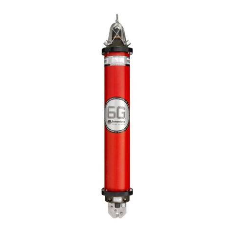
Figure 3-1 – Type 8270 Directional Wideband Sub-Mini 6G®
Figure 3-2 – Type 8270 Directional Wideband Sub-Mini 6G® Outline Drawing
October 2011

WSM6 Manual Document Ref: UM-8270-000
Issue: A Rev 0
Section 3
6
Figure 3-3 – Type 8271 Omni-Directional Wideband Sub-Mini 6G®
Figure 3-4 – Type 8271 Omni Directional Wideband Sub-Mini 6G® Outline Drawing
The connector end-cap shields the electrical charging socket and ON/OFF switch (refer to Figure
3-5 and Figure 3-6). When not in use, the unit should be switched OFF to preserve battery charge.
It should be noted, however, that Nickel Metal Hydride batteries do self-discharge over a number of
weeks so the WSM6 should always be fully charged before use.
Figure 3-5 – Type 8270 Directional Wideband Sub-Mini 6G® End-Cap
October 2011
This manual suits for next models
1
Table of contents
Other Sonardyne Marine Radio manuals

