Sonardyne UM-8300-Compatt 6 User manual

UM-8300-Compatt 6
User Manual for the Type 8300 Compatt 6 (and
Variants)
Issue B, Rev 3
Date of Issue:24th April 2019
Sonardyne International Limited
Blackbushe Business Park
Yateley, Hampshire
GU46 6GD, United Kingdom
920-0026
T. +44 (0) 1252 872288
F. +44 (0) 1252 876100
E. support@sonardyne.com
www.sonardyne.com

© 2016–2019 Sonardyne International Limited. All rights reserved.
This user manual is the copyright and intellectual property right of Sonardyne International Limited
(“Sonardyne”) and is provided solely for the customer’s use of the Sonardyne equipment as described
in this user manual and in accordance with Sonardyne’s then prevailing terms and conditions of sale.
This user manual has been compiled to the best of Sonardyne’s knowledge and belief, but no
representation, warranty (whether express or implied) or guarantee is made to any persons or legal
entities as to the accuracy, reliability or completeness of the information contained in this user manual.
This user manual contains the proprietary, confidential information of Sonardyne and other third parties
and as such may not be used, disclosed or placed in the public domain (by whatever means) by the
customer except expressly in accordance with and subject to the above referenced terms and
conditions of sale.
The copyright and any and all intellectual property rights of any and all third parties which may be
referenced in this user manual or which may have provided proprietary products and/or software
and/or documentation (in whatever format) to Sonardyne in respect of the Sonardyne equipment as
described in this user manual are hereby duly acknowledged. The provision of any and all such
products and/or software and/or documentation by Sonardyne shall be subject to and in accordance
with the relevant third parties’ terms and conditions or the Sonardyne then prevailing conditions of sale,
as appropriate.
The Sonardyne equipment described in this user manual is protected by various UK and US Patents
and other patents internationally and registered trademarks of Sonardyne International Limited.
User Manual for the Type 8300 Compatt 6
(and Variants)
UM-8300-Compatt 6
Issue B3
i

Contacting the Sonardyne Support Team
24-hour Emergency Telephone Helpline: +44 (0) 1252 877600
The Sonardyne 24-hour helpline is answered at the UK Headquarters during normal office hours
(08:00 to 17:00). Outside these hours, your call is automatically transferred to an agency, which logs
the details of your emergency and alerts the appropriate Sonardyne personnel.
Our aim is to make sure emergency requests are dealt with immediately during office hours, and are
responded to within 30 minutes at all other times.
Please note the helpline is for emergency use only.
If you require NON-EMERGENCY product support, please contact your nearest Sonardyne office.
Alternatively, contact the Sonardyne Head Office:
Sonardyne International Ltd
Blackbushe Business Park
Yateley
Hampshire
GU46 6GD
United Kingdom
Telephone: +44 (0) 1252 872288
Fax: +44 (0) 1252 876100
Email: support@sonardyne.com
Note
Email and telephone support is available during normal UK office hours (08:00 to 17:00).
User Manual for the Type 8300 Compatt 6
(and Variants)
UM-8300-Compatt 6
Issue B3
ii

Contents
Contacting the Sonardyne Support Team ii
Amendment History x
Section 1 – Introduction 1
1.1 Scope of this Manual 1
1.2 Purpose of this Manual 1
1.3 Related Publications 1
1.4 Conventions 1
Section 2 – Safety 2
2.1 Introduction 2
2.2 Safety Procedures 2
2.2.1 Warnings 2
2.2.2 Cautions 3
2.2.3 Handling Procedures for CMOS Devices and Circuit Boards 4
Section 3 – Technical Description 5
3.1 Introduction 5
3.2 Compatt 6 Series (Type 8300) 5
3.2.1 Compatt 6 5
3.2.2 Midi Compatt 6 6
3.2.3 Mini Compatt 6 6
3.2.4 Maxi Compatt 6 7
3.3 Type 8300 Variants 7
3.3.1 Dynamic Positioning Transponder 6 (Type 8301) 7
3.3.2 Pressure Inverted Echo Sounder (Type 8302) 8
3.3.3 Autonomous Monitoring Transponder (Type 8305) 8
3.3.4 Modem 6 Transponder (Type 8307) 9
3.3.5 Sensor Logging Transponder (Type 8308) 9
3.4 Housing Labelling 10
3.4.1 Top Label 10
3.4.2 Bottom Label 10
3.5 Endcaps 12
3.5.1 Transducer Endcap 12
3.5.2 Sensor Endcap 13
3.6 Connector 14
3.7 Battery 14
3.7.1 Battery Type 14
3.7.2 Battery Disconnect Fob 15
3.7.3 Battery Replacement 15
Section 4 – Installation 17
4.1 Introduction 17
4.2 Pre-Use Checks 17
4.2.1 Check the Pressure Relief Vent Valve 17
4.2.2 Floatation 17
User Manual for the Type 8300 Compatt 6
(and Variants)
UM-8300-Compatt 6
Issue B3
iii

4.2.3 Anchor Weights 17
4.2.4 Strops 18
4.2.5 Mounting Guidelines for Endcaps with an Inclinometer 18
Section 5 – Deployment 22
5.1 Introduction 22
5.2 Lifting 22
5.3 Deployment from Ship 22
5.3.1 Recommended Method 22
5.3.2 Additional Deployment methods 22
Section 6 – Operation 26
6.1 Introduction 26
6.2 Operational Modes 26
6.2.1 Responder Mode 26
6.2.2 Operating Notes for External Power Out 26
6.2.3 Modem 6 27
6.2.4 Operating Notes for Inclinometer Variants 27
Section 7 – Retrieval and Storage 28
7.1 Introduction 28
7.2 Retrieval Planning 28
7.3 Retrieval from the Water 28
7.4 After Retrieval 28
7.5 Storage 29
Section 8 – Maintenance 30
8.1 Introduction 30
8.2 Retrieval from the Water 30
8.3 Cleaning 30
8.4 Inspection 30
8.5 Lubrication 31
8.5.1 Subconn Connectors 31
8.5.2 Endcap O-Rings 31
8.6 Scheduled Maintenance and Recalibration 32
8.6.1 Pressure Sensor Oil Top-Up 33
8.6.2 Depth Sensor (Digiquartz®) Recalibration 33
8.7 Pressure Relief Vent Valve 34
8.7.1 Operating the Pressure Relief Vent Valve 34
8.8 Battery Maintenance 35
8.8.1 Checking the Battery Condition 35
8.8.2 Disconnecting and Replacing the Battery 35
8.9 Removal and Fitment of a Directional Transducer Endcap 39
8.9.1 Directional Transducer Endcap Removal 39
8.9.2 Fitment of the Directional Transducer Endcap 41
8.10 Removal and Fitment of Omni-Directional Transducer Endcap 43
8.10.1 Omni-Directional Transducer Endcap Removal 43
8.10.2 Fitment of the Omni-Directional Transducer Endcap 46
User Manual for the Type 8300 Compatt 6
(and Variants)
UM-8300-Compatt 6
Issue B3
iv

8.11 Removal and Fitment of the Sensor Endcap 47
8.11.1 Sensor Endcap Removal 47
8.11.2 Sensor Endcap Fitment 52
8.12 Corrosion Removal 58
Section 9 – Functional Test 59
9.1 Introduction 59
9.2 Test Equipment 59
9.2.1 6G Terminal Lite 59
9.2.2 iWAND Hand Test Device 59
9.3 Operational Testing 60
9.3.1 Connecting the Dual Serial Cable 61
9.3.2 Checking the Wideband Acoustics 63
9.3.3 Checking the Sensor Measurements 67
9.3.4 Checking the Release Mechanism 69
9.3.5 Creating a Test Report 74
Section 10 – Firmware Update 77
10.1 Introduction 77
10.2 Firmware Update Procedure 77
10.3 DAS Firmware Update 80
Section 11 – Fault Diagnosis 84
11.1 Introduction 84
11.2 Fault Types 84
Section 12 – Spares 86
12.1 Introduction 86
12.2 Recommended Spares 86
12.2.1 Batteries 86
12.2.2 Sonardyne Upgrades 86
12.2.3 Miscellaneous Parts 86
12.2.4 Cables 87
Section 13 – Technical Specifications 88
13.1 Mechanical – Compatt 6 Type 3111 with Release Endcap 88
13.2 Mechanical – Mini Compatt 6 Type 3131 88
13.3 Mechanical – Midi Compatt 6 Type 3141 with Release Endcap 88
13.4 Mechanical – Maxi Compatt 6 Type 3141 with Release Endcap 89
13.5 Battery Life 89
13.6 6G Battery Life Estimator 90
13.7 Communication Port 91
13.8 Acoustic 91
13.9 Environmental 91
13.10 Sensors 91
13.11 Responder Input Trigger (Sync Input) 92
13.12 Nett Upthrust 93
13.13 Outline Drawings 93
User Manual for the Type 8300 Compatt 6
(and Variants)
UM-8300-Compatt 6
Issue B3
v

13.13.1 3,000 m Omni-Directional 93
13.13.2 3,000 m MF Omni-Directional Aluminium Housings 93
13.13.3 3,000 m MF Directional Aluminium Housings 98
13.13.4 3,000 m LMF Omni-Directional Aluminium Housings 102
13.13.5 3,000 m LMF Directional Aluminium Housings 106
13.13.6 3,000 m MF Omni-Directional Super Duplex Housings 109
13.13.7 3,000 m LMF Omni-Directional Super Duplex Housings 111
13.13.8 5,000 m MF Omni-Directional Aluminium Housings 113
13.13.9 5,000 m MF Directional Aluminium Housings 116
Appendix A – Acoustic Positioning Methods 119
A.1 Long Baseline (LBL) 119
A.1.1 Hardware 119
A.1.2 Principles 119
A.1.3 Beacon Numbers 120
A.1.4 Baseline Distance 120
A.1.5 Calibration 120
A.2 Short Baseline (SBL) 120
A.2.1 Hardware 120
A.2.2 Baseline Distances 121
A.2.3 Principles 121
A.3 Ultra-short Baseline (USBL) 122
A.3.1 Hardware 122
A.3.2 Principles 122
A.4 Long / Ultra-short Baseline (L/USBL) 123
A.4.1 Hardware 123
A.4.2 Principles 123
A.4.3 Non-Critical Operations 123
A.4.4 Critical Operations 123
A.4.5 Dual Operation 124
A.5 Long-short USBL (LSUSBL) 124
A.5.1 Hardware 124
A.5.2 Principles 124
Appendix A – Basic Principles of Transponder Interrogation and Reply 125
A.1 Transceivers 126
A.2 Command and Telemetry Functions 126
A.3 Communicating via RS232 126
A.4 Acoustic Navigation System Principles 127
Definitions 128
Figures
Figure 3–1 Compatt 6 Transponder – Omni-Directional 6
Figure 3–2 Compatt 6 Transponder – Directional 6
Figure 3–3 Midi Compatt 6 6
User Manual for the Type 8300 Compatt 6
(and Variants)
UM-8300-Compatt 6
Issue B3
vi

Figure 3–4 Mini Compatt 6 7
Figure 3–5 Maxi Compatt 6 7
Figure 3–6 Dynamic Positioning Transponder 6 Transponder 8
Figure 3–7 Pressure Inverted Echo Sounder Transponder 8
Figure 3–8 Autonomous Monitoring Transponder 9
Figure 3–9 Sensor Logging Transponder 10
Figure 3–10 Transducer Endcap Internal Connectors 12
Figure 3–11 Example of a Sensor Endcap 13
Figure 3–12 Subconn MCBH8F Connector 14
Figure 3–13 Battery Disconnect Fob 15
Figure 4–1 Example of Inclinometer Mounting Kit 19
Figure 4–2 Example of Stab Mounting Kit 20
Figure 4–3 Recommended Specification for Inclinometer Endcap Mounting Plate 21
Figure 5–1 Rolling the Transponder off the Deck 22
Figure 5–2 Lowered by Vessel Crane or A-Frame – Single Transponder Installation 23
Figure 5–3 Lowered by Vessel Crane or A-Frame – Multiple Transponder Installation 23
Figure 5–4 Acoustic Release used as a Crane Hook 24
Figure 5–5 Slip Hook with Integral Swivel 25
Figure 5–6 ROV grabs one metre loop of Rope 25
Figure 6–1 Responder Input 26
Figure 8–1 Fitting the Bulkhead Plate 38
Figure 8–2 Inspecting the Transducer Endcap 38
Figure 8–3 Removing the Protective Guard 39
Figure 8–4 Removing the Guard and Bump Stop 40
Figure 8–5 Removing Transducer Housing using the Opening Tools (Omni-Directional shown for
Reference) 40
Figure 8–6 Cleaning the O-ring Seals (Omni-Directional shown for Reference) 41
Figure 8–7 Refitting the Guard and Bump Stop 42
Figure 8–8 Securing the Bump Stop and Guard 43
Figure 8–9 Removing the Clamp Rings 44
Figure 8–10 Removing the Rubber Bump Stop 44
Figure 8–11 Removing Transducer Housing using the Opening Tools 45
Figure 8–12 Cleaning the O-ring Seals 45
Figure 8–13 Fitting Clamp Rings and Bumper Stop 47
Figure 8–14 Securing Bump Stop to Clamp Rings 47
Figure 8–15 Figure 0-13 Remove the Sensor Endcap 48
Figure 8–16 Removing the Sensor Endcap 49
Figure 8–17 Sensor Endcap and Chassis 49
Figure 8–18 Disconnecting PL1 Connection from the Interface PCB Assembly 50
Figure 8–19 Disconnecting PL2 Connection from the Interface PCB Assembly 50
Figure 8–20 Disconnecting the Ribbon Cable from the Interface PCB Assembly 51
Figure 8–21 Disconnecting the Sensor Endcap from the Main Chassis 51
Figure 8–22 Abutting Chassis and Sensor Endcap 53
Figure 8–23 Securing the Sensor Endcap to the Chassis 53
Figure 8–24 Interface PCB Connections 54
Figure 8–25 Inserting the Chassis into the Housing 54
Figure 8–26 Fitting the Bulkhead Plate over the Pins 57
Figure 9–1 Compatt 6 Connected to the PC using the Dual Serial Cable 60
Figure 9–2 Dual Serial Cable 61
User Manual for the Type 8300 Compatt 6
(and Variants)
UM-8300-Compatt 6
Issue B3
vii

Figure 9–3 Release Mechanism Fully Open 70
Figure 9–4 Release Mechanism Fully Closed 70
Figure 9–5 Release Mechanism Rotating Lock 70
Figure 9–6 Release Test 71
Figure 9–7 Manually Closing the Release Mechanism 73
Figure 9–8 Transponder Test Report pdf 76
Figure 13–1 Estimated Battery Life (Alkaline) 89
Figure 13–2 Estimated Battery Life (Standard Lithium) 90
Figure 13–3 6G Battery Life Estimator App. 90
Figure 13–4 6G Battery Life Estimator App. QR Code 90
Figure 13–5 Type 830x-3111 (Standard Length 3,000 m MF Omni-Directional) 94
Figure 13–6 Type 830x-3121 (Maxi 3,000 m MF Omni-Directional) 95
Figure 13–7 Type 830x-3131 (Mini 3,000 m MF Omni-Directional) 96
Figure 13–8 Type 830x-3141 (Midi 3,000 m MF Omni-Directional) 97
Figure 13–9 Type 830x-3113 (Standard Length 3,000 m MF Directional) 98
Figure 13–10 Figure 0-10 Type 830x-3123 (Maxi 3,000 m MF Directional) 99
Figure 13–11 Type 830x-3133 (Mini 3,000 m MF Directional) 100
Figure 13–12 Type 830x-3143 (Midi 3,000 m MF Directional) 101
Figure 13–13 Type 830x-3115 (Standard Length 3,000 m LMF Omni-Directional) 102
Figure 13–14 Type 830x-3125 (Maxi 3,000 m LMF Omni-Directional) 103
Figure 13–15 Type 830x-3135 (Mini 3,000 m LMF Omni-Directional) 104
Figure 13–16 Type 830x-3145 (Midi 3,000 m LMF Omni-Directional) 105
Figure 13–17 Type 830x-3116 (Standard Length 3,000 m LMF Directional) 106
Figure 13–18 Type 830x-3126 (Maxi 3,000 m LMF Directional) 107
Figure 13–19 Type 830x-3146 (Midi 3,000 m LMF Directional) 108
Figure 13–20 Type 830x-3311 (Standard Length 3,000 m MF Omni-Directional) 109
Figure 13–21 Type 830x-3321 (Maxi 3,000 m MF Omni-Directional) 110
Figure 13–22 Type 830x-3315 (Standard Length 3,000 m LMF Omni-Directional) 111
Figure 13–23 Type 830x-3325 (Maxi 3,000 m LMF Omni-Directional) 112
Figure 13–24 Type 830x-5211 (Standard Length 5,000 m MF Omni-Directional) 113
Figure 13–25 Type 830x-5221 (Maxi 5,000 m MF Omni-Directional) 114
Figure 13–26 Type 830x-5241 (Midi 5,000 m MF Omni-Directional) 115
Figure 13–27 Type 830x-5213 (Standard Length 5,000 m MF Directional) 116
Figure 13–28 Type 830x-5223 (Maxi 5,000 m MF Directional) 117
Figure 13–29 Type 830x-5243 (Midi 5,000 m MF Directional) 118
Figure A–1 Typical LBL System 119
Figure A–2 Typical SBL System 121
Figure A–3 Typical USBL System 122
Figure A–4 Typical L/USBL system 123
Tables
Table 1–1 Related Publications 1
Table 1–2 Conventions used in this Manual 1
Table 3–1 Type Number Identification 11
Table 3–2 Address Range 12
Table 7–1 Storage Conditions 29
Table 8–1 Lubricants 31
Table 8–2 Maintenance and Recalibration Schedule 33
User Manual for the Type 8300 Compatt 6
(and Variants)
UM-8300-Compatt 6
Issue B3
viii


Amendment History
The amendment history records all amendments and additions made to this manual.
Issue Revision Date Comments Section Page
A 0 30/09/2010 First Issue All All
A 1 30/11/2010 Minor Changes All -
A 2 07/12/2010 Removed Section 4.2 – changing the
inclinometer scaling range as this no longer
applies for 6th Generation Transponders. Other
minor typographical changes.
4.2 -
A 3 17/01/2011 Improved drawing resolution and details in
Section 15. Section 4.1 inclinometer endcap
drawing and mounting instructions clarified.
4.1, 15 -
A 4 21/01/2011 Improved the wording consistency. 2 -
B 0 18/02/2013 Reformatted the manual. Improved overall
construction and consistency. Include new 6G
Terminal Lite Software.
All All
B 1 19/08/2013 ECN12238
Stock code for PCBs in recommended spares
listing changed.
Section 6.3 External Connector Pin-Out.
12
6.3
111
29
B 2 25/10/2016 OB11543/11657
Maintenance Section updated.
Storage details added.
References to iWAND added.
References to battery disconnect fob added.
Outline Drawings updated.
Sections re-organised and general update.
7
7.5
8
All
13.13
All
All
24
All
All
88–110
All
B 3 24/04/2019 General update All All
User Manual for the Type 8300 Compatt 6
(and Variants)
UM-8300-Compatt 6
Issue B3
x

User Manual for the Type 8300 Compatt 6
(and Variants)
UM-8300-Compatt 6
Issue B3
Section 1 – Introduction
1.1 Scope of this Manual
This User Manual describes the safe installation, operation and maintenance of the Type 8300 (and
variants) wideband transponder. The information and procedures within this manual are based on
Sonardyne’s experience and knowledge.
1.2 Purpose of this Manual
This user manual contains information for anyone involved with installing, operating and maintaining
the Type 8300 (and variants) wideband transponder.
This manual may be printed in part or whole but cannot be copied or changed. Copyright of this
manual remains with Sonardyne International Limited at all times.
To ensure the safety of the installer and operator is maintained it is important that all warnings and
cautions in Section 2 "Safety" of this manual and in any related manuals are read and fully understood.
1.3 Related Publications
To ensure the equipment is operated safely, a Sonardyne Safety Manual is supplied with this user
manual. It is important that the Sonardyne Safety Manual is read and fully understood before
proceeding with any activity on the equipment.
Publication Title
Sonardyne Safety Manual Operational and Safety Precautions
UM-8300-099 User Manual for 6G Terminal Lite (included on the 6G Utilities media)
UM-8315 User Manual for the Type 8315 iWAND (included with the iWAND)
IM-Modem 6 Modem 6 Integration Manual
Table 1–1 Related Publications
1.4 Conventions
Format Convention
Boldface Type User Input, Menu Options, Keys, e.g. Click OK
Arrow (>) Selection of an additional menu item e.g. File>Save
Italic Type References to Figures, Tables, Sections and internal/external source
Table 1–2 Conventions used in this Manual
Section 1 – Introduction 1

User Manual for the Type 8300 Compatt 6
(and Variants)
UM-8300-Compatt 6
Issue B3
Section 2 – Safety
2.1 Introduction
Before any activity is carried out on the equipment, it is recommended that the included Sonardyne
Safety Manual and all warnings and cautions in this manual are read and fully understood.
It is recommended that the operator complies with the Health and Safety Regulations applicable to the
vessel and the region before operating this equipment.
Operators and service personnel must be familiar with the normal operating and safety procedures for
the subsea equipment being operated.
Documentation must be consulted whenever a or warning symbol is found on the equipment,
in order to determine the nature of the potential hazard and any actions which must be taken.
If any additional equipment is used, any warnings and cautions in the equipment user manual must be
read and fully understood and the equipment must only be used as specified by the manufacturer.
If the equipment is used in a manner not specified by the manufacturer, the protection provided by the
equipment may be impaired.
The safety of any system incorporating this equipment is the responsibility of the assembler of the
system.
2.2 Safety Procedures
Warning and Caution terms used in this manual are described below:
lWarning: indicates potential for property damage, personal injury or death.
lCaution: indicates either potential damage to hardware, malfunction or loss of data.
2.2.1 Warnings
Personal protection. Appropriate protective equipment such as protective footwear, hard hat and
gloves must be worn when handling or carrying out any procedures involving Sonardyne and other
equipment.
Heavy equipment. Many Sonardyne products and equipment types, such as transponders,
transceivers, cable drums etc. require Manual Handling Equipment (MHE) for lifting due to their heavy
weight. If MHE is not available, it is the responsibility of the operator to perform a manual handling risk
assessment prior to carrying out manual lifting/handling. See the individual equipment documentation
for weight specifications.
Electric shock. Electric shock hazard risk is present when dismantling or assembling the
equipment. High voltages are present inside the transponder. Dismantling or assembling the
equipment must only be carried out by trained personnel.
High Internal Pressures Risk. Due to the high internal pressure risk, dismantling the sub-sea
equipment must only be carried out by trained personnel.
High Internal Pressures Risk. Make sure the pressure relief vent valve is manually operated to
release any internal pressure before attempting to dismantle the equipment.
Section 2 – Safety 2

User Manual for the Type 8300 Compatt 6
(and Variants)
UM-8300-Compatt 6
Issue B3
Risk of toxic gases and corrosive liquids. Do not stand in direct line with the end of the transponder
when operating the pressure relief vent valve. Sudden release of high pressure gases could cause
injury to personnel. Wear Personal Protective Equipment such as goggles when operating the
pressure relief vent valve.
Risk of burns. If the battery pack has been exposed to flooding, corrosive liquids may be present.
Personal protective equipment, such as gloves and goggles, must be worn to handle the battery pack.
Risk of burns. Do not carry out maintenance on the transponder if the housing is hot. Lower the
transponder into cold water and wait for the housing to cool. Wear Personal Protective Equipment
such as gloves.
Risk of impact injury. Do not stand in line with the endcap when removing from the transponder.
Any internal pressure could rapidly force the endcap from the transponder like a projectile.
Risk of Explosion. Do not fit unauthorised battery pack types into the transponder.
Risk of Explosion. For lithium and lithium Ion battery packs, Class D fire extinguishers should be
used. Do not use any other type of extinguisher.
Crush Risk. Do not place hands near the Release Mechanism when in operation. The mechanism
is opened with a high pressure spring which could trap fingers.
2.2.2 Cautions
Risk of equipment damage. All instruments must be maintained according to their individual
operating manuals. Failure to follow recommended procedures could result in instrument failure, and
loss of system integrity.
Irritant chemicals. Molykote 44 is a mild irritant. When lubricating the connector faces, personal
protective equipment such as gloves and goggles must be worn.
Battery Power Failure. Do not charge the battery packs in any way not outlined in this manual.
Failure to follow instructions may result in a loss of battery pack life or damage to the battery packs.
Dispose of batteries in accordance with local health and safety and environmental regulations.
Loss of Current Protection. Do not allow the transponder to be cooled or heated during the
charging process as the over current protection component characteristics may change adversely.
Damage to Sealing. Make sure the O-ring seals do not become damaged during removal of the
endcaps.
Damage to Connectors. Failure to clean sand or silt correctly could result in damage to the
connectors and O-ring seals.
Multiple beacon address conflict. Do not operate multiple beacons on the same Quickset
Wideband settings in the water at the same time. The address must be unique to any one beacon
operating in the same acoustic area.
Loss of Connector Integrity. Do not over apply grease to the female connector. Grease build up
will affect connector integrity.
Section 2 – Safety 3

User Manual for the Type 8300 Compatt 6
(and Variants)
UM-8300-Compatt 6
Issue B3
Equipment Damage. Only use the authorised battery packs in the transponder. Failure to use the
correct batteries could cause damage to the equipment.
Protective coating failure. Do not use any abrasive brushes or sharp tools to remove marine
growth when cleaning the instrument as this will damage the protective coating and increase the risk
of corrosion.
2.2.3 Handling Procedures for CMOS Devices and Circuit Boards
Complementary Metal Oxide Semi-Conductor (CMOS) devices have diode input protection against
adverse electrical environments such as electrostatic discharge.
Severe electrical transient voltages can be generated during handling.
Static voltages generated by a person walking across a common waxed floor have been measured in
the 4 to 15 kilovolt range. These static high voltages are potentially dangerous when discharged into a
CMOS electronic device, due to the energy stored in the capacity (~300 pF) of the human body at
these voltage levels.
Present CMOS gate protection structures can generally protect against over-voltages. This is usually
sufficient except in the severe cases.
All CMOS devices should be stored and transported in materials that are anti-static. CMOS devices
must not be inserted into conventional plastic “snow”, Styrofoam or plastic trays, but should be left in
their original container until ready for use.
Operators must comply with safety precautions.
Completed assemblies should be placed in anti-static containers before being moved to stations.
All low impedance equipment (pulse generators, etc.) should be connected to CMOS inputs only after
the CMOS is powered up. This type of equipment should be disconnected before power is turned off.
A circuit board containing CMOS devices is an extension of the device and the same handling
precautions apply. Unprotected handling of any board containing edge connectors wired directly to
CMOS device inputs can cause damage.
Do not insert or remove CMOS devices from their original or test sockets with power applied. Check
all power supplies to be used for testing CMOS devices to ensure there are no voltage transients
present.
All CMOS devices should be placed on a grounded bench surface and operators should ground
themselves prior to handling devices, since a person can be statically charged with respect to the
bench surface. Wrist straps in contact with skin are strongly recommended.
Nylon or other static generating materials should not come in contact with CMOS circuits.
When lead straightening or hand soldering is necessary, provide ground straps for the apparatus used
and ensure the soldering irons are grounded.
Section 2 – Safety 4

User Manual for the Type 8300 Compatt 6
(and Variants)
UM-8300-Compatt 6
Issue B3
Section 3 – Technical Description
3.1 Introduction
The Type 8300 (and variants) series Wideband®2 Transponders are designed for positioning, data
telemetry, data logging functions and remote monitoring of subsea instrumentation.
The Wideband®2 technology uses a correlation reception technique with phase encoded signals over
a wide range of carrier frequencies. Signal coding allows for hundreds of channels enabling multiple
users to work in the same area without interference.
The 8300 (and variants) series Wideband®2 transponders can be fully integrated with other
Sonardyne products from the 6G®range.
This manual covers the following Wideband®2 Transponders:
lType 8300 – Compatt 6 Transponder, including:
oStandard length
oMini
oMidi
oMaxi
lVariants, including:
oType 8301 – Dynamic Positioning Transponder 6 (DPT 6)
oType 8302 – Pressure Inverted Echo Sounder (PIES)
oType 8305 – Autonomous Monitoring Transponder 6 (AMT)
oType 8307 – Modem
oType 8308 – Sensor Logging Transponder (SLT)
3.2 Compatt 6 Series (Type 8300)
The Compatt 6 transponder is designed specifically for full Long Baseline (LBL) subsea deployments.
The standard transducer housing is hard anodised aluminium but it is also available in aluminium
bronze and super duplex stainless steel as well as standard, mini, midi and maxi lengths, depending
on the operational requirements.
The Compatt 6 has a depth rating of 3,000 to 7,000 metres and is available as an omni-directional and
directional transducer. The transponders are available with different sensor options and release
mechanisms. The Compatt 6 is identified by a red coloured housing label.
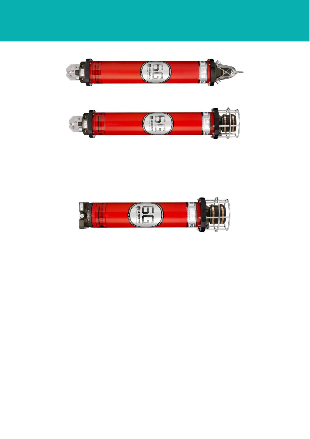
3.2.1 Compatt 6
The Compatt 6 is approximately 1035 mm overall length (depending on transducer type and sensor
options) with a hard anodised pressure housing approximately 135 mm diameter, protected by a red
sleeve. The sensor endcap can contain a stainless steel release mechanism for releasing an anchor
weight. The Compatt 6 can be fitted with either a lithium or alkaline battery.
Section 3 – Technical Description 5
User Manual for the Type 8300 Compatt 6
(and Variants)
UM-8300-Compatt 6
Issue B3
Figure 3–1 Compatt 6 Transponder – Omni-Directional
Figure 3–2 Compatt 6 Transponder – Directional
3.2.2 Midi Compatt 6
The Midi is approximately 784 mm overall length (depending on transducer type and sensor options).
The hard-anodised pressure housing is approximately 135 mm diameter. The lithium battery has
approximately 30% of the capacity of the standard lithium battery with the same functionality.
Figure 3–3 Midi Compatt 6
3.2.3 Mini Compatt 6
The Mini is approximately 570 mm overall length (depending on transducer type) and is basically the
same as the Midi Compatt 6 but without any sensor options. The hard-anodised pressure housing is
approximately 135 mm diameter. The lithium battery has approximately 30% of the capacity of the
standard lithium battery with the same functionality.
Section 3 – Technical Description 6
User Manual for the Type 8300 Compatt 6
(and Variants)
UM-8300-Compatt 6
Issue B3
Figure 3–4 Mini Compatt 6
3.2.4 Maxi Compatt 6
The Maxi is approximately 1604 mm overall length (depending on transducer type and sensor options)
and is designed for long life and/or high intensity applications. The hard-anodised pressure housing is
approximately 135 mm diameter. The lithium battery has twice the capacity of the standard lithium
battery with the same functionality.
Figure 3–5 Maxi Compatt 6
3.3 Type 8300 Variants
Many of the Type 8300 variants shown below are also available in mini, midi and maxi lengths.
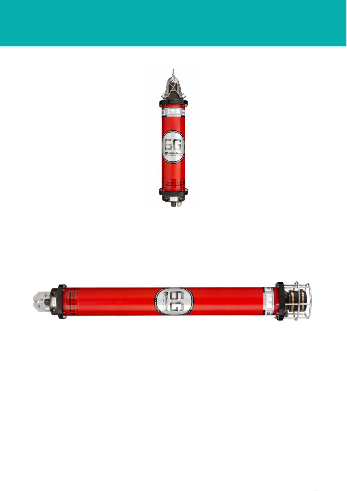
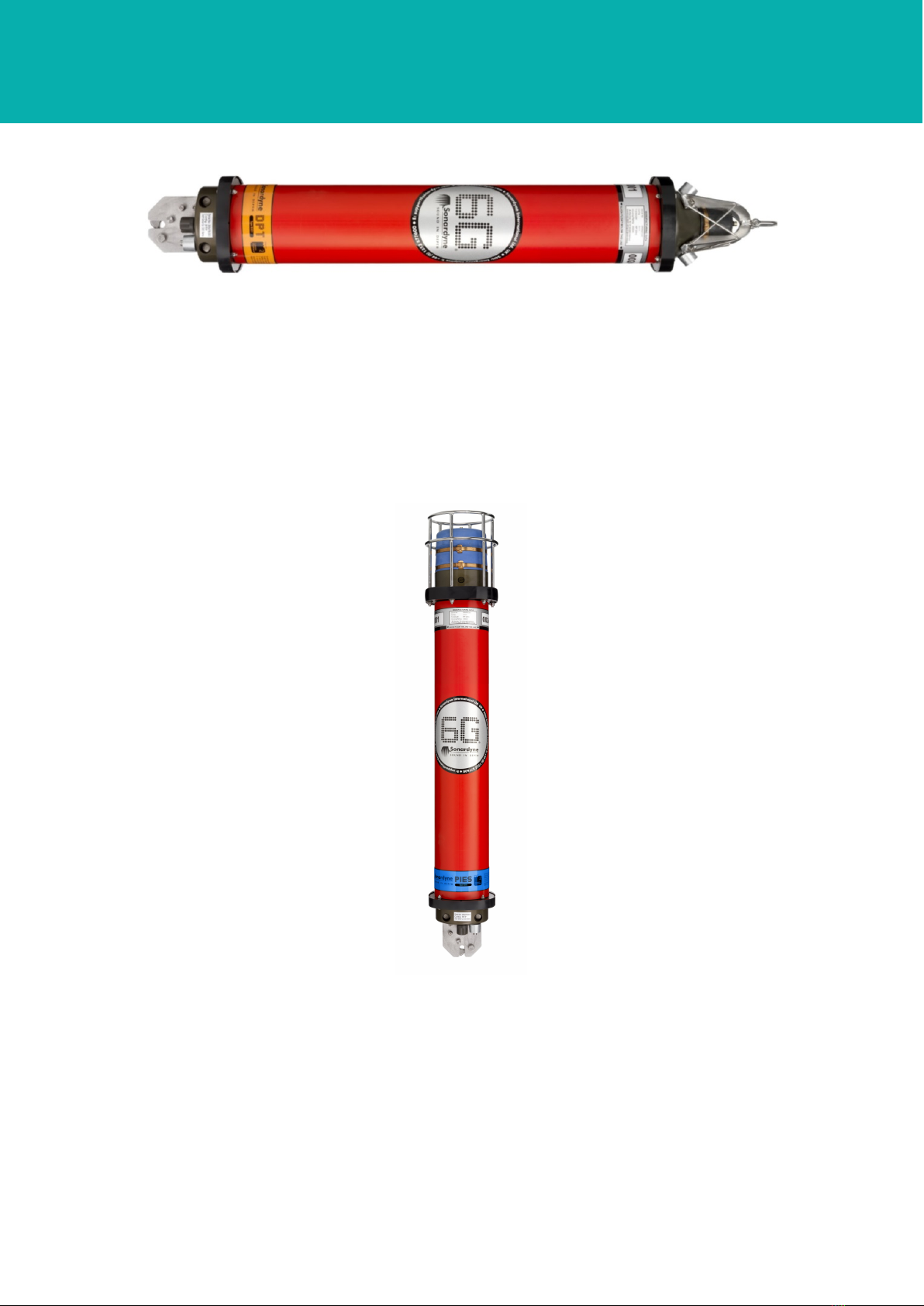
3.3.1 Dynamic Positioning Transponder 6 (Type 8301)
The Dynamic Positioning Transponder 6 (DPT 6) is a USBL focused beacon designed specifically for
dynamic positioning applications where structure tracking and baseline measurements are not
required. The transducer is available as an omni-directional and directional, with a depth rating of
3000 and 5000 metres. The transponder’s pressure housing is hard anodised and protected by a red
sleeve. The sensor endcap can contain a stainless steel release mechanism for releasing an anchor
weight. The DPT 6 is identified by an orange coloured housing label.
Section 3 – Technical Description 7
User Manual for the Type 8300 Compatt 6
(and Variants)
UM-8300-Compatt 6
Issue B3
Figure 3–6 Dynamic Positioning Transponder 6 Transponder
3.3.2 Pressure Inverted Echo Sounder (Type 8302)
The Pressure Inverted Echo Sounder (PIES) is a long-life sensor logging node that measures the
average sound velocity through a column of water from the seabed to the sea surface. The transducer
is LMF directional, with a depth rating of 3000 and 6000 metres. The transponder’s pressure housing
is hard anodised and protected by a red sleeve. The sensor endcap can contain a stainless steel
release mechanism for releasing an anchor weight. The PIES is identified by a blue coloured housing
label.
Figure 3–7 Pressure Inverted Echo Sounder Transponder
3.3.3 Autonomous Monitoring Transponder (Type 8305)
The Autonomous Monitoring Transponder (AMT) has the same capabilities as the Compatt 6 with
additional capabilities to periodically log sensor readings and make acoustic baseline measurements.
The AMT has a depth rating of 3000 metres and is available as an omni-directional and directional
transducer. The transponder’s pressure housing is hard anodised and protected by a red sleeve. The
sensor endcap can contain a stainless steel release mechanism for releasing an anchor weight. The
AMT is identified by a yellow coloured housing label.
Section 3 – Technical Description 8

User Manual for the Type 8300 Compatt 6
(and Variants)
UM-8300-Compatt 6
Issue B3
Figure 3–8 Autonomous Monitoring Transponder
3.3.4 Modem 6 Transponder (Type 8307)
The Modem 6 Transponder has the same capabilities and mechanical specification as the Compatt 6
but operates as a modem only. The Modem is identified by a green coloured label.
A Modem 6 Integration Manual (IM-Modem 6) is available for configuring the Modem 6 for operational
use.
3.3.5 Sensor Logging Transponder (Type 8308)
The Sensor Logging Transponder (SLT) has the same capabilities as the Compatt 6 with additional
capabilities of autonomously acquiring sensor data without surface control. The SLT has a depth
rating of 3000 metres and is available as an omni-directional and directional transducer. The
transponder’s pressure housing is hard anodised and protected by a red sleeve. The sensor endcap
can contain a stainless steel release mechanism for releasing an anchor weight. The SLT is identified
by a blue coloured housing label.
Section 3 – Technical Description 9
This manual suits for next models
4
Table of contents
Other Sonardyne Marine Radio manuals


Popular Marine Radio manuals by other brands

West Marine
West Marine VHF 150 owner's manual

Uniden
Uniden MC 1020 operating guide

Garmin
Garmin WORKFORCE 320 installation manual

Enrock Marine
Enrock Marine EMC56W Installation & owner's manual
uAvionix
uAvionix tailBeaconX STC Instructions for Continued Airworthiness and Maintenance Manual

Icom
Icom IC-M802 Programming instructions


