Sonardyne 8300 User manual

QUICK START GUIDE
TYPE 8300 TRANSPONDERS
FIRMWARE UPGRADE GUIDE
To access more
information on the
firmware, download a
free QR code app on
your Smartphone and
then scan this code.
QSG-UP-8300-00-A2
07/2013
910-0001

SAFETY
PRODUCT SUPPORT
Email: [email protected]
Tel: +44 (0) 1252 872288
Should you require NON-EMERGENCY product support for your firmware upgrade, email and
telephone product support is available during normal UK office hours (08:00-17:00).
Alternatively, please contact your nearest Sonardyne Office. Visit www.sonardyne.com for full
details.
In emergency situations, the Sonardyne 24 hour helpline is answered during normal office
hours - 08:00-17:00. Outside these hours, your call is automatically transferred to an agency
who will log the details of your emergency and alert the appropriate Sonardyne personnel.
Our aim is to ensure that emergency requests are dealt with immediately during office hours
and are responded to within 30 minutes at all other times.
SONARDYNE 24HR EMERGENCY HELPLINE: UK +44 (0) 1252 877600
To make sure the equipment operates correctly, make sure the correct firmware
is being installed.
Do not use the test cables to lift the equipment.
CAUTIONS
STEP 1
Heavy equipment. The Type 8300 Series of transponders, when out of water, weigh
between 22.8 kg and 35 kg (depending on type). Manual handling Equipment (MHE)
must be used to move the transponders. If MHE is not available, then a manual
handling assessment must be carried out prior to carrying out manual lifting /
handling. Personal Protective Equipment such as protective footwear and gloves must
be worn before lifting the equipment.
Make sure the equipment is clean and dry before removing the connection point
cover and connecting any test cables.
WARNING
It is recommended the operator complies with the Health and Safety Regulations applicable to the
vessel and the region before operating this equipment.
If the equipment is used in a manner not specified by the manufacturer, the protection provided by
the equipment may be impaired.
Documentation must be consulted whenever the warning symbol is found on the equipment, in
order to find out the nature of the potential hazard and any actions which must be taken.
EQUIPMENT SUPPLIED
STEP 2
This Quick Start Guide gives instructions on how to upgrade the HOST or DAS firmware
used in the Type 8300 Transponders using the Dual Test Cable.
The table below lists all transponders this Quick Start Guide is relevant to and their
identifying colour band.
To enable the firmware upgrade process, a Dual Test Cable is supplied with the
equipment.
If the correct test lead is not available, please contact Sonardyne for product support.
Refer to Step 1 for details.
Transponder Number Transponder Type Colour Band
8300
8301
8305
8307
8308
Compatt 6
DPT(i)6
AMT
Modem
SLT
Make sure all Warnings and Caution labels on the equipment are read and
understood. Refer to the equipment manual for further information and assistance.

CONNECTING THE EQUIPMENT
STEP 3
Use the following instructions to connect the Dual Serial Cable to the Transponder.
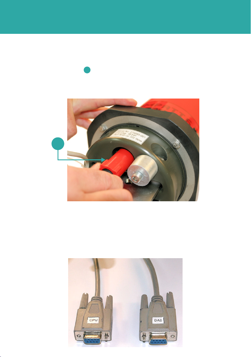
1 Locate the round Dual Serial Cable connection point on the Transponder.
2 Using the special tool, remove the protective cover from the Dual Serial Cable
connection point .
1
1
2
3
3 Check the connection points are free from obstructions and dirt .
4 Position the Dual Serial Cable in the correct orientation and insert into the
connection point.
2
3
STEP 4
CONNECTING THE EQUIPMENT
6 The other end of the Dual Serial Cable has the CPU and DAS connectors for use
when requested in the instructions.
5 Make sure the Dual Serial Cable is inserted fully, and secure in place by screwing in
the red protective cover clockwise.
1
1
OPERATING THE EQUIPMENT
Use the following procedure to upgrade the HOST firmware. To upgrade the DAS
firmware refer to Step 8.
1 Using the Dual Test Cable, connect the CPU connector to a comms port on the PC.
Make note of which comms port is used.
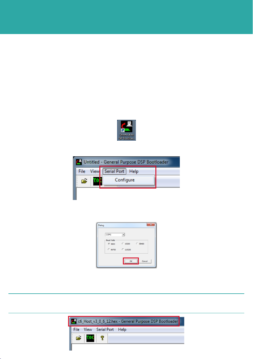
2 Double click on the GP Bootloader.exe icon to open the program.
STEP 5
3 From the menu toolbar select Serial Port, then Configure.
5 Select File, then Open.
6 Browse to the location where the new firmware is stored. Select the new firmware.
4 In the Dialog screen select the correct COM port and Baud Rate 38400, 56700
or 115200. Click OK.
2NOTE
The new firmware version will appear in the Bootloader title bar.
HOST FIRMWARE UPGRADE PROCEDURE
OPERATING THE EQUIPMENT
STEP 6
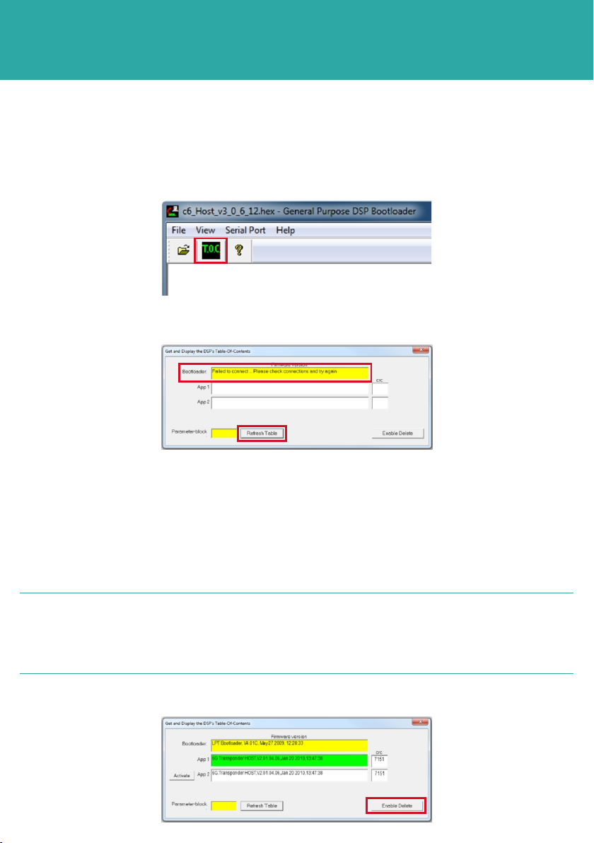
8 If connections are not made successfully, an error message will appear.
7 On the main screen, select TOC.
9 Check all cables are connected correctly to the PC.
10 Go to the Device Manager facility on the PC and check the CPU cable is
connected to the correct Comms Port.
11 Click Refresh after checking the connections.
12 If all the cable connections have been made, the window will refresh.
2 NOTES
Two spaces are available on the hardware for firmware. If all spaces are full,
then one must be deleted to accommodate the firmware upgrade.
The green highlighted App indicates the currently active firmware.
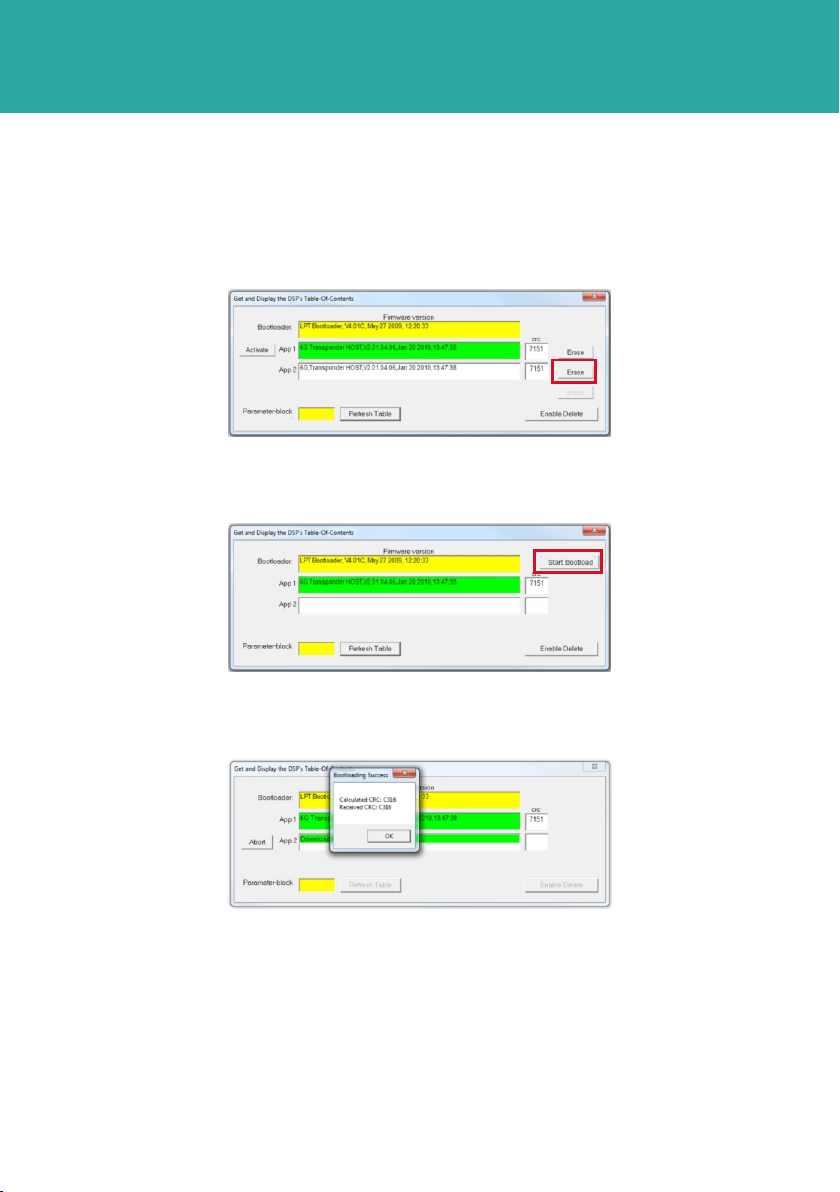
13 To erase an application, click Enable Delete.
HOST FIRMWARE UPGRADE PROCEDURE
OPERATING THE EQUIPMENT
HOST FIRMWARE UPGRADE PROCEDURE
STEP 7
14 Click Erase next to the app to be deleted.
16 A percentage uploading bar will scroll across the App.
15 Click Start Bootload to start uploading the new firmware.
17 When the upload is complete a Bootloading Success window will appear.
18 Click OK.
19 The new uploaded program will appear in the selected App window.
20 Close the Get and Display the DSP’s Table of Content window.
21 To confirm the new firmware is working, click on TOC and the new firmware should
be displayed highlighted in green.
22 Close all windows.
OPERATING THE EQUIPMENT
STEP 8
1 A CD, installed with 6G Terminal Lite and DASCAL software is supplied to assist
with the upgrade of the DAS firmware.
2 Connect the Dual Test Cable to the Transponder as detailed in Step 3.
3 Connect the CPU and DAS connectors to comms ports on the PC.
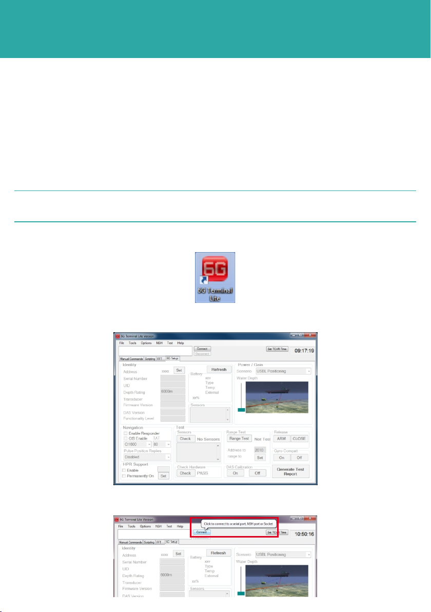
5 The 6G Terminal Lite homepage will open on a blank 6G setup tab.
Make a note of which comms port each connector is connected to.
2NOTE
4 Double click on the 6G Terminal Lite icon to open the software.
6 Click Connect to connect the transponder to the software.
DAS FIRMWARE UPGRADE PROCEDURE

OPERATING THE EQUIPMENT
STEP 9
7 In the Select Port window select the correct port the PC is connected to and the
Baud Rage from the drop down menus. Click Connect.
9 Open the DAS software by double clicking on the icon.
8 In the 6G Setup tab, select the DAS Calibration On button to upgrade the DAS
firmware.
DAS FIRMWARE UPGRADE PROCEDURE
OPERATING THE EQUIPMENT
STEP 10
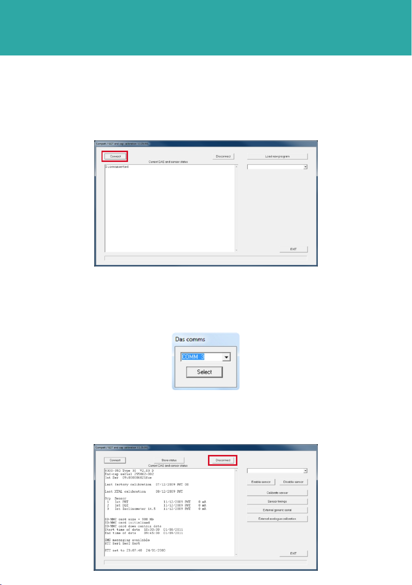
13 Click Select.
14 When the DASCAL program opens select Disconnect.
11 A DAS Comms selection window will open.
12 Choose the correct COMMS port for the DAS connection, from the drop down
selection.
10 On the DAS page click Connect.
DAS FIRMWARE UPGRADE PROCEDURE
OPERATING THE EQUIPMENT
STEP 11
18 The firmware upgrade will now commence. This process will take approximately 4-5
minutes.
19 When the new firmware upgrade has completed, a Reprogramming Succeeded
notification will be displayed in the DAS homepage main screen.
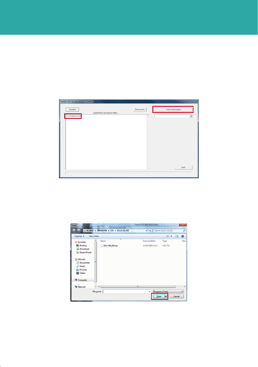
17 Navigate to the location of the new program. Click Open.
15 Disconnected will appear in the main screen.
16 Select Load New Program to load the new firmware.
DAS FIRMWARE UPGRADE PROCEDURE

OPERATING THE EQUIPMENT
DAS FIRMWARE UPGRADE PROCEDURE
STEP 12
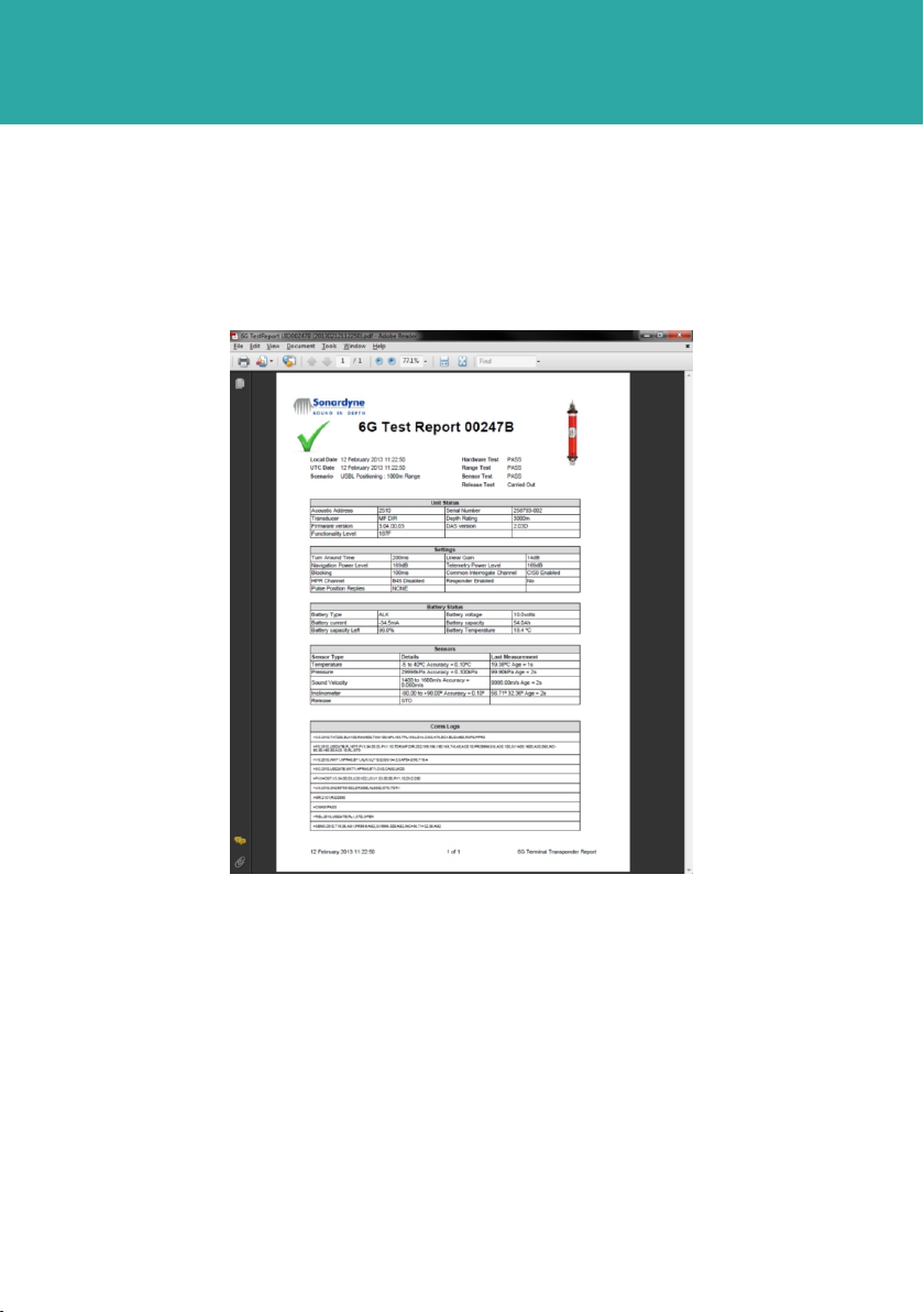
22 On completion of the firmware upgrade a test report can be created.
21 On the 6G Setup tab click the DAS Calibration Off.
If only one Comms Port connection has been used, then close the DAS program
by selecting Exit Program, disconnect the DAS connection from the Comms Port
and replace it with the CPU connection on the Dual Test Cable. Open the 6G
Terminal Lite program by double clicking the icon.
2NOTE
20 Click Exit to return to the 6G Terminal Lite homepage.

STEP 13
OPERATING THE EQUIPMENT
1 On the 6G Setup tab click Generate Test Report.
2 A file location window will open to save the created Test Report pdf.
The Test Report will list all information provided on the 6G Setup tab of the 6G Terminal
Lite software.
3 Choose a location to store the Test Report then press OK.
CREATING A TEST REPORT
RETRIEVAL & PACKING
1 On completion of the firmware upgrade make sure the HOST or DAS programmes
are closed.
2 Make sure any power supplied to the equipment is switched OFF at source.
3 Disconnect the CPU and DAS connections from the Comms Ports on the PC.
4 Disconnect the Test Cable from the Transponder.
5 Using the special tool fit the protective cover to the Test Cable attachment point.
6 Stow the Test Cable in the protective packaging supplied with the Transponder for
further use.
STEP 14
OPERATING THE EQUIPMENT
CREATING A TEST REPORT
5 On completion of the review, the 6G Terminal Lite software can be closed.
4 A pdf test report will now be created and saved in the designated location. A tick
will appear to indicate the transponder has passed all the tests.

Global Headquarters, UK
T. +44 (0) 1252 872288
F. +44 (0) 1252 876100
Houston, USA
T. +1 281 890 2120
F. +1 281 890 7047
24/7 Emergency Hotline
+44 (0) 1252 877600
Email Support
Website
www.sonardyne.com
Twitter
@sonardyne
Aberdeen, UK
T. +44 (0) 1224 707875
F. +44 (0) 1224 707876
Rio das Ostras, Brazil
T. +55 22 2123 4950
F. +55 22 2123 4951
Singapore, Asia
T. +65 6542 1911
F. +65 6542 6937
ACOUSTIC POSITIONING INERTIAL NAVIGATION
llWIRELESS COMMUNICATION lSONAR IMAGING
QSG-UP-8300-00-A2
07/2013
910-0001
Table of contents
Other Sonardyne Marine Radio manuals


Popular Marine Radio manuals by other brands

Garmin
Garmin GTX 330 pilot's guide

Garmin
Garmin VHF 315 Series owner's manual

Raymarine
Raymarine Ray 90 Installation & operating instruction

Cobra Marine
Cobra Marine MR HH600W FLT GPS BT owner's manual

Uniden
Uniden UM455 owner's manual

True Heading
True Heading AIS-CTRX CARBON Operation & installation manual


DIGITAL YACHT
DIGITAL YACHT AIT2000 Technical notes

Rhotheta
Rhotheta RT-1000 user manual

Benthos
Benthos 865-A INSTRUCTIONS FOR THE INSTALLATION, OPERATION AND MAINTENANCE

Furuno
Furuno FM-2510 Quick reference card

Uniden
Uniden UM415 owner's manual

Simons Voss Technologies
Simons Voss Technologies MobileKey manual