Sonardyne DPT6 User manual

QUICK START GUIDE
DPT6 C6
BATTERY REPLACEMENT
/ /AMT6 TRANSPONDERS
To access more information
on the transponders battery
change, download a free
QR code app on your
Smartphone and then scan
this code.
QSG-BR-8300-00
11/2011
910-0002

SAFETY
High pressure hazard risk when dismantling sub-sea equipment. Dismantling must only be
carried out by trained personnel.
Electric shock hazard risk when dismantling the equipment. Dismantling must only be carried
out by trained personnel.
Make sure the Pressure Relief Vent Valve is manually operated, in a well ventilated area, to
release any internal pressure before attempting to remove the end-cap.
Risk of burns. Do not change the battery pack if the housing is hot. Lower the transponder
overboard and wait for the housing to cool. Wear Personal Protective Equipment such as gloves.
Risk of impact injury. Do not stand in-line with the end-cap when removing from the
transponder.
Make sure the equipment is dry before dismantling.
Do not fit unauthorised battery pack types into an instrument.
For Lithium and Lithium Ion battery packs, Class D fire extinguishers should be used. Do not use
any other type of extinguisher.
The C6 and DPT transponders weigh between 23 and 29 kg. A minimum of two persons is
required to manouevre the equipment.
The AMT transponder weighs between 23 and 35 kg. A minimum of three persons is required to
manouevre the equipment weighing 35 kg, and a minimum of two persons to manouevre the
equipment weighing 23 kg.
WARNINGS
STEP 1
It is recommended the operator complies with the Health and Safety Regulations applicable to the vessel and the
region before operating this equipment.
If the equipment is used in a manner not specified by the manufacturer, the protection provided by the
equipment may be impaired.
Documentation must be consulted whenever the warning symbol is found on the equipment, in order to find
out the nature of the potential hazard and any actions which must be taken.
The batteries used in the 8300 transponders can be lithium based. Due to the high risks associated with these
types of batteries, it is important that the safety instructions in this Quick Start Guide are read and fully
understood.
Only trained and qualified personnel must carry out the battery replacement procedure detailed in this Quick
Start Guide.
Do not expose batteries to extreme temperatures, in excess of 60°C, to prevent reduction in
battery life.
CAUTION
PRODUCT SUPPORT
Email: [email protected]
Tel: +44 (0) 1252 872288
Should you require NON-EMERGENCY product support for your transponder, email and telephone product
support is available during normal UK office hours (08:00-17:00 GMT). Alternatively, please contact your
nearest Sonardyne Office. Visit www.sonardyne.com for full details.
In emergency situations, the Sonardyne 24 hour helpline is answered during normal office hours - 08:00-17:00
GMT. Outside these hours, your call is automatically transferred to an agency who will log the details of your
emergency and alert the appropriate Sonardyne personnel. Our aim is to ensure that emergency requests are
dealt with immediately during office hours and are responded to within 30 minutes at all other times.
SONARDYNE 24HR EMERGENCY HELPLINE: UK +44 (0) 1252 877600

STEP 2
PREPARING THE EQUIPMENT
This Quick Start Guide gives instructions on how to replace the battery in the 8300 series
transponders.
Before attempting to dismantle the transponder to replace the battery, the transponder
must be cleaned and thoroughly dried.
Use the following procedure to prepare the equipment.
1 Make sure the equipment has been rinsed in clean fresh water.
2 Remove any excess marine growth.
3 Dry the transponder with clean lint free cloth.
4 Inspect the transponder for any signs of damage, temperature.
5 If the transponder body is hot, lower into cold water to cool. When the body has
cooled, dry with clean lint free cloth.
6 Move the transponder to a clean dry environment.
7 Inspect the transponder around the Pressure Relief Vent Valve for deposits. This
would indicate the battery has vented due to water ingress or electronics/battery
malfunction. In these circumstances the battery pack and internal electronics may
have been severely damaged.
Risk of burns. Do not carry out any maintenance if the transponder housing is
hot. Lower the transponder overboard and wait for the housing to cool.
High pressure hazard risk when dismantling sub-sea equipment. Dismantling
must only be carried out by trained personnel.
The C6 and DPT transponders weigh between 23 and 29 kg. A minimum of two
persons is required to manouevre the equipment
The AMT transponders weigh between 23 and 35 kg. A minimum of three
persons is required to manouevre the equipment weighing 35 kg. A minimum of
two persons is required to manouevre the equipment weighing 23 kg.
WARNINGS
Before carrying out any activity on the equipment, make sure all Warnings and
Caution labels on the equipment and within this Quick Start Guide are read and
understood. Refer to the equipment manual for further information and assistance.

STEP 3
DISMANTLING THE EQUIPMENT
Use the following procedure to dismantle the equipment and remove the battery.
3 If the Pressure Relief Vent Valve is not flush, this would indicate an increase in
internal pressure.
High pressure hazard risk when dismantling the sub-sea equipment, refer to the
Safety Section. Must only be carried out by trained personnel.
Electric shock hazard risk when dismantling the equipment, refer to the Safety
Section. Must only be carried out by trained personnel.
Make sure the Pressure Relief Vent Valve is operated in a well vented area, to
remove any risk of internal pressure build up.
The C6 and DPT transponders weigh between 23 and 29 kg. A minimum of two
persons is required to manouevre the equipment
The AMT transponders weigh between 23 and 35 kg. A minimum of three
persons is required to manouevre the equipment weighing 35 kg. A minimum of
two persons is required to manouevre the equipment weighing 23 kg.
WARNINGS
1 Clean the area around the Pressure Relief Vent Valve , make sure any marine
growth is removed.
2 Check the Pressure Relief Vent Valve is flush with the housing.
1
1
1
STEP 4
DISMANTLING THE EQUIPMENT
Do not stand in directly in-line with the end-cap when removing it from the
transponder.
Do not remove the end-cap if there is a gap between the end-cap and the
housing body. Refer to the User Manual for instructions.
Do not continue to remove the end-cap if movement is felt during removal
of the clamp rings. Refer to the equipment User Manual for assistance.
WARNINGS
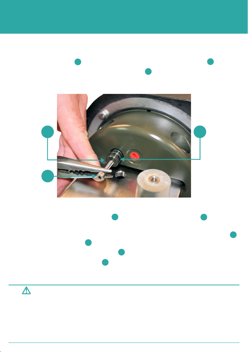
4 Screw an M4 screw ( not supplied) into the Pressure Relief Vent Valve plug.
5 Slowly pull the out the Pressure Relief Vent Valve to release any internal pressure,
and reveal the two ‘O’ rings. A pair of long nose pliers can be used to assist.
21
1
1
2
3
6 Wait for any internal pressure to be fully vented from the housing.
7 With the Pressure Relief Vent Valve pulled out, inspect the ‘O’ rings , for signs of
damage.
8 A light coating of petroleum jelly can be applied to the Pressure Relief Vent Valve
to lubricate the ‘O’ rings .
9 Release the Pressure Relief Vent Valve and allow it to reseat.
10 If the Pressure Relief Vent Valve does not fully reseat, gently apply pressure to
make sure it is flush with the end-cap.
13
1
3
1
1
Other manuals for DPT6
1
This manual suits for next models
2
Table of contents
Other Sonardyne Marine Radio manuals


