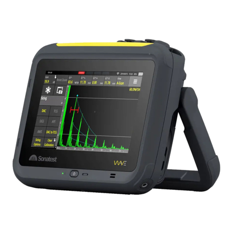
Sonatest Wave User manual

Wave
User Manual

2 Wave User Manual
Version 4

Wave User Manual 3
Version 4
Contents
1INTRODUCTION 9
1.1 WHAT IS WAVE? 9
1.2 APPLICATION CONCEPT 9
2WAVE CARRY CASE 10
3WAVE PHYSICAL CHARACTERISTICS 11
3.1 THE SCREEN 11
3.2 THE POWER BUTTON 11
3.3 LED BEHAVIOURS 12
3.3.1 THE DEVICE IS TURNED OFF 12
3.3.2 THE DEVICE IS BOOTING 12
3.4 THE UT CONNECTORS 13
3.4.1 THE UT CONNECTOR PINOUTS 13
3.5 THE GPIO CONNECTOR 14
3.5.1 GPIO CONNECTOR PINOUT 14
3.6 THE EXPANSION PORT 15
3.7 THE USB-C CONNECTOR 15
3.7.1 CHARGING THROUGH USB-C 16
3.7.2 USB-C TO ETHERNET ADAPTER 16
3.8 THE BATTERY 17
3.8.1 BATTERY ICON 17
3.9 THE UNIT’S STAND 17
4POWERING UP AND SHUTTING DOWN 19
4.1 SHUTTING DOWN THE UNIT 19
5MAIN SCREEN OVERVIEW 20
5.1 HOME SCREEN 20
5.2 APP DESCRIPTION SCREEN 20
5.2.1 PREFERRED CONFIGURATION 21
5.3 INSPECTION SCREEN 22
5.4 REPORT SCREEN 23
6THE BASICS –INSPECTION SCREEN 24
6.1 THE MENU ITEMS 24
6.2 PERMANENT ON-SCREEN ACTION BUTTONS 25
6.3 FREEZE 25
6.4 SCREEN CAPTURE 26
6.5 GATES 26
6.5.1 ENABLING A GATE 26
6.5.2 MOVING GATES AND CHANGING GATE PROPERTIES 27
6.5.3 SETTING A GATE ON A SCAN PLAN VIEW 28

4 Wave User Manual
Version 4
6.6 ALARMS 29
6.6.1 ALARM ON-SCREEN LED COLOURS 29
6.6.2 COMPLEX ALARMS 30
6.7 LAYOUT 30
6.8 TOOLBAR 31
6.8.1 FULL SCREEN MODE 32
6.8.2 SAVE A CONFIGURATION 32
6.8.3 CREATE A REPORT 33
6.8.4 QUIT AN APPLICATION 33
7MEASUREMENTS 34
7.1 MEASUREMENT DEFINITIONS 36
7.2 MEASUREMENTS REFERENCE TABLE 37
7.3 MEASUREMENT VALUES 41
7.4 MEASUREMENT COORDINATES REFERENCES 41
7.5 MEASUREMENTS UNITS 42
7.6 FSH% MEASUREMENT IN GATES 42
8ULTRASONIC PARAMETERS –ADVANCED NOTIONS 43
8.1 THE A-SCAN VIEW 43
8.1.1 REFERENCE A-SCAN 43
8.1.2 A-SCAN ZOOM 43
8.1.3 AUTO 80% FSH 44
8.2 TX/RX MENU 44
8.3 SIGNAL MENU 45
8.3.1 FILTER REFERENCE TABLE 46
8.4 GATE ADVANCED SETTINGS 47
8.4.1 GATE POLARITY 47
8.4.2 SETTING UP AN ADAPTIVE GATE IN GATE MODE 47
9THE PROBE SELECTION 48
10 THE PART WIZARD 50
10.1 PART TYPES 50
10.1.1 PART TYPE DIMENSIONS 50
10.2 WELD TYPES 51
10.2.1 WELD DIMENSIONS 54
10.3 WIZARD 55
10.3.1 PART VIEW 55
11 THE SCAN PLAN VIEW 56
11.1 SCAN PLAN MENU 56
11.2 MOVING A PROBE 57
12 AUTO CAL AND SIZING METHODS 58
12.1 AUTO CAL 58
12.2 DAC 58

Wave User Manual 5
Version 4
12.2.1 CREATE A DAC CURVE 58
12.2.2 DAC SIZING OPTIONS 60
12.2.3 ABSOLUTE AND RELATIVE DAC GAIN MODE 60
12.2.4 AMPLITUDE CORRECTED AND UNCORRECTED MEASUREMENTS 61
12.3 TCG 62
12.3.1 CREATE A TCG CURVE 62
12.3.2 TCG SIZING OPTIONS 64
12.4 DGS 64
12.4.1 PERFORMING A DGS CALIBRATION 64
12.4.2 DGS SIZING OPTIONS 66
12.5 AWS 66
12.5.1 PERFORMING AN AWS CALIBRATION 67
12.5.2 AWS SIZING OPTIONS 67
12.6 API 68
12.6.1 PERFORM AN API CALIBRATION 68
12.6.2 API SIZING OPTION 69
12.7 T-LOG 69
12.7.1 PARAMETER DESCRIPTIONS 70
12.7.2 COLOUR PALETTE 71
12.7.3 T-MIN FUNCTION 72
12.7.4 CSV FILES 72
13 REPORT 74
13.1 WORKFLOW 74
13.2 SCREENSHOT 75
13.2.1 NAME AND COMMENT 76
13.2.2 RATING AND COLOUR 76
13.2.3 CANCEL AND SAVE 76
13.3 CREATE A REPORT 77
13.3.1 FROM THE INSPECTION SCREEN 77
13.3.2 FROM THE APP DESCRIPTION SCREEN 78
13.4 REPORT CREATING SCREEN 78
13.4.1 SOURCE 78
13.4.2 GENERAL 80
13.4.3 INSPECTION SUMMARY 81
13.4.4 IMAGES 83
13.4.5 UT PARAMETERS 84
13.4.6 PROBE AND WEDGE 86
13.5 REPORT PREVIEW 86
13.5.1 NAVIGATION IN THE PDF REPORT 88
13.6 SAVE AND NAME A REPORT 88
13.7 VIEW AN EXISTING REPORT 89
13.7.1 DELETE AN EXISTING REPORT 90
13.8 RETRIEVE A REPORT 90
13.8.1 WITH WAVE COMPANION. 90
13.8.2 BY EMAIL 90
14 SETTINGS 92

6 Wave User Manual
Version 4
14.1 GENERAL 92
14.1.1 BRIGHTNESS 92
14.1.2 HIGH CONTRAST 93
14.1.3 DATE AND TIME 93
14.2 LANGUAGE 93
14.3 NETWORK 93
14.3.1 WIRED NETWORK CONNECTION 94
14.3.2 NETWORK CONNECTION VIA WI-FI95
14.4 ABOUT 96
14.5 LEGAL 96
15 UPDATES 97
15.1 INTERNET UPDATE 97
15.2 USB-C UPDATE 97
16 REMOTE CONNECTION AND VNC 98
16.1 CONNECTION TO A NETWORK 98
16.2 SHARING YOUR INTERNET CONNECTION FROM YOUR LAPTOP 98
16.3 SHARING YOUR INTERNET CONNECTION FROM YOUR MOBILE PHONE 99
17 MENUS AND PARAMETERS REFERENCE 100
18 WAVE COMPANION 106
18.1 CONNECT WAVE TO THE WAVE COMPANION 106
18.2 VERSION COMPATIBILITY 106
19 QUALITY ASSURANCE 107
20 MAINTENANCE 108
20.1 TEMPERATURES 108
20.2 SCREEN 108
20.3 CONNECTORS 108
20.4 BATTERY AND POWER SUPPLY 108
20.5 USB-C CONNECTOR 109
20.6 TRAVELLING 109
21 ADDITIONAL RESOURCES 110
21.1 PROBES 110
21.2 ACCESSORIES 110
21.3 SONATEST WEBSITE 110
22 WARRANTY AND DISCLAIMERS 111
22.1 WARRANTY 111
22.2 DISCLAIMER OF LIABILITY 111
23 TROUBLESHOOTING 112

8 Wave User Manual
Version 4
Copyright
All rights reserved. No part of this publication may be reproduced, stored in a retrieval
system or transmitted in any form or by any means, electronic, mechanical,
photocopying, recording, or otherwise, without the prior written permission of Sonatest
Limited.
Sonatest Limited or its subsidiaries provide this manual “AS IS” without warranty of any
kind, either express or implied. Included but not limited to the implied warranties or
conditions of merchantability or fitness for a particular purpose. In NO events shall
Sonatest Limited, its subsidiaries, its directors, officers, employers, or agents be liable for
indirect, special, incidental, or consequential damages, even if Sonatest Limited or its
subsidiaries have been advised of the possibility of such damages arising from any defect
or error in this manual or product.
Specifications and information contained in this manual are furnished for informational
use only, and are subject to change at any time without notice, and should not be
construed as a commitment by Sonatest Limited or its subsidiaries.

Wave User Manual 9
Version 4
1Introduction
1.1 What is Wave?
Wave is a new generation, smart flaw detector. It has been designed to simplify the work
of technicians and engineers. It is based on simple, custom-made applications that can
be tailored to meet the specific requirements of different inspection procedures.
Wave also brings new tools to make the interpretation of A-Scans easier. A scan plan and
complete 2-D view can be used to represent the part being inspected. A smart ray tracer
then displays the ultrasonic beam path travelling within the piece of material, precisely
showing the echoes, echo amplitude and gate positions.
As well, Wave allows using all the main sizing methods, including DAC and DGS to name
a few.
1.2 Application Concept
Applications are a subset of the Default application that is pre-installed on all shipped
Wave units. The Default app allows access to all functionalities and features, and you
have the flexibility of setting all parameters to any possible value.
Applications are easily created using the Wave Companion Software. Once created, these
new apps are transferred and installed on a Wave unit. They are then immediately
available to the Wave user.
A custom app will greatly simplify the instrument usage by building a much simplified
environment. This allows streamlining your task, as well as lowering the risk of misusing
the instrument.

10 Wave User Manual
Version 4
2Wave Carry Case
The Wave carry case includes:
●Wave instrument;
●Smart Li-on battery pack;
●AC/DC battery charger;
●Ethernet to USB-C adapter;
●Ethernet cable;
●Quick Start Guide booklet;
●Couplant bottle.
Figure 1 –Wave Transport Case

Wave User Manual 11
Version 4
3Wave Physical Characteristics
3.1 The Screen
The seven-inch screen of Wave occupies most of the front area of the instrument. It is
made of glass, which makes it very easy to clean, and is protected on all sides with a
rubberised contour.
Figure 2 –Wave with the touch screen, power button, and LED indicator
The unit does not present any physical button apart from the power button. Operating
the unit is done using the integrated touch panel. Using the latest projective capacitive
(P-CAP) technology, the touch panel allows multi-touch as well as drag and pinch
gestures. Using working gloves is not a problem as the touchscreen controller has been
programmed to adapt to different circumstances. Moreover, water or couplant will not
interfere or affect the behaviour of finger detection.
3.2 The Power Button
The power button is used to turn the unit on. Once the unit is turned on, it is possible to
double-click the power button and disable the touchscreen. A lock screen icon appears in
the top right corner of the screen. Double-click the power button again to enable the
touchscreen.
Figure 3 - Lock screen icon
Touchs
creenT
ouchsc
reen
LED
Power button

12 Wave User Manual
Version 4
NOTE: Disabling the touch screen can be useful for cleaning the screen.
IMPORTANT: To turn the unit off, you must use the on-screen power-
off button appearing at the bottom right of the Home screen. See
Section 4 for more details.
3.3 LED Behaviours
The LED light, next to the power button, provides information on Wave’s status.
3.3.1 The Device Is Turned off
•If Wave is not connected to the power supply, which means it is not charging, the
LED light is turned off.
•If Wave is connected to the power supply, which means the device is charging, the
LED will blink.
•If Wave is connected to the power supply and it is fully charged, a solid green LED
light is displayed.
3.3.2 The Device Is Booting
•During the booting phase, the LED will blink for 5 seconds until the Home screen
appears.

Wave User Manual 13
Version 4
3.4 The UT Connectors
The UT connectors are located on top of the unit. There is one TX/RX connector and one
RX connector. They are identified directly on the casing. These UT connectors can be
LEMO or BNC.
When using the instrument in pulse-echo mode, only the TX/RX output is used. For pitch
and catch, both TX/RX and RX must be hooked up to the probe.
Figure 4 –Wave connectors and the expansion ports
3.4.1 The UT Connector Pinouts
The following tables describe the pinouts of the UT connectors. Figure 5 and Figure 6
illustrate the localisation of the pinouts in the Lemo connector and BNC.
Table 1 –TX/RX connector pinouts
Pin number
I/O
I/O type
Description
1
In/Out
Analogue
Ultrasound pulse transmitter/receiver
2
Out
Power
Ground
Table 2 –RX connector pinouts
Pin number
I/O
I/O type
Description
1
In/Out
Analogue
Ultrasound pulse receiver
2
Out
Power
Ground
Expansion
GPIO
RX
TX/RX

14 Wave User Manual
Version 4
Figure 5 –Lemo ultrasound connector pinouts
Figure 6 –BNC ultrasound connector pinouts
3.5 The GPIO Connector
An additional connector is present just beside the UT connectors. This is the GPIO
connector for encoder inputs and digital outputs namely used for alarms.
NOTE: The UT and GPIO connectors, when not used, should always
be hidden by their protective covers. Though these connectors are
rugged and rated IP67, they can eventually become damaged by the
accumulation of dirt, which may cause some contacts to fail.
3.5.1 GPIO Connector Pinout
The following table describes the pinouts of the GPIO connector. Figure 7 illustrates the
localisation of these pinouts.
Table 3 –GPIO connector pinouts
Pin number
I/O
I/O type
Description
1
Out
Power
5V DC power supply (500 mA limit)
2
Out
Power
Ground
3
Out
TTL 5V
Alarm Output 1 / General Purpose Output 1
4
Out
TTL 5V
Alarm Output 2 / General Purpose Output 2
5
Out
TTL 5V
Alarm Output 3 / General Purpose Output 3
6
Out
TTL 5V
Alarm Output 4 / General Purpose Output 4
7
In
TTL 5V
Encoder 1 Phase A
8
In
TTL 5V
Encoder 1 Phase B
9
In
TTL 5V
Encoder 2 Phase A
10
In
TTL 5V
Encoder 2 Phase B
11
In
TTL 5V
External Trigger Input
12
In/Out
RS-485
Noninverting Receiver Input and Driver Output
13
In/Out
RS-485
Inverting Receiver Input and Driver Output
14
Out
Analogue
Proportional output
15
Out
Power
Ground
16
Out
Power
Ground

Wave User Manual 15
Version 4
Figure 7 –GPIO connector pinouts
The following table presents information regarding the part number of the GPIO.
Table 4 –GPIO part number
Type
Part number
Description
Wave connector
(Lemo)
HEG.1K.316.CLNP
K Series (1K), 16-pin, receptacle, centre key (G),
watertight
Mating connector
(Lemo)
FGG.1K.316.CLAC
K Series (1K), 16-pin, straight plug, centre key
(G)
3.6 The Expansion Port
The expansion port is a Sonatest proprietary connection that will allow adding extra
accessories. The protector cap over the expansion port must remain in place to protect
the connector. It should only be removed when attaching an accessory.
3.7 The USB-C Connector
The USB-C connector can be found on the left side (front view) of the instrument. It is
protected and lies behind a small door made of soft material.

16 Wave User Manual
Version 4
Figure 8 –Wave from the left side
3.7.1 Charging Through USB-C
Wave’s USB-C port is hence used to recharge the instrument’s battery. The AC-DC power
supply provided with the unit allows fast charging. Typically, a full recharge of a dead
battery to 100% charge level will take just over 3 hours even if the unit is turned on during
recharge.
USB-C hubs can be inserted between the power supply and the instrument, allowing extra
connections (like being hooked-up to a wired network) at the same time as the
instrument’s battery is being recharged.
IMPORTANT: Sonatest recommends a few USB-C hubs. Please follow
these recommendations as some manufacturers may not provide
fully USB-C compliant devices. Go to Sonatest’s website to view an
updated list of these pre-tested hubs.
3.7.2 USB-C to Ethernet Adapter
The unit comes with a small USB-C to wired Ethernet adapter. This is used to connect your
unit to your local network and allow you to exchange data between the instrument and
a laptop computer, for example. For more information regarding the data transfers,
including installing custom applications on your Wave unit, consult the “Wave Companion
User Manual”, where all information about creating custom apps as well as transferring
them to a Wave unit is provided.
USB-C
door

Wave User Manual 17
Version 4
3.8 The Battery
Wave is powered by a 72 W/h battery, typically capable of providing 10 hours of
continuous use. The battery compartment is located on the back of the unit, and it is
accessible just behind the battery door. Note that to remove the battery, you have to pull
on the battery tab that will push back the additional battery latch that secures the battery
in order to prevent any disconnect in the event of a shock or a drop. Pulling on the tab
will make the battery come out of its compartment.
Figure 9 –Wave battery compartment door
NOTE: Always turn off the instrument before removing the battery.
Doing differently may cause undesirable effects.
3.8.1 Battery Icon
The battery icon changes colour depending on the charge level of the device. In addition,
if the device is at10% or less, it is recommended to save the configuration, turn off the
device and replace the battery.
Figure 10 –Battery icon
3.9 The Unit’s Stand
At the back of the Wave instrument, there is a stand providing a full 180⁰ of adjustment,
without any position limitation in between 0⁰ and 180⁰. The stand, when fully extended,
can serve as a handle to carry the unit. The anti-skid material of both the handle and
around the instrument makes it easy to find a sturdy way to have the unit lay on pretty
much any surface.
Battery
compartme
nt

18 Wave User Manual
Version 4

Wave User Manual 19
Version 4
4Powering Up and Shutting Down
The instrument is powered up by pressing the power-on button located at the bottom,
just under the display.
Figure 11 –How to power up the Wave
4.1 Shutting Down the Unit
Shut down the unit from the Home screen. By pressing the red On/Off button, you will
be presented with a confirmation screen where you can select between Shutdown,
Reboot, or Cancel.
Figure 12 –Shutting down from the Home screen
Power button

20 Wave User Manual
Version 4
5Main Screen Overview
There are several screens available in Wave. This section highlights the main features of
each screen. For more details, see the corresponding sections.
5.1 Home Screen
When powering up your instrument, you will be presented with the Home screen, where
all the available applications appear. By default, Wave has seven (7) applications: Default,
Default imperial, DAC, DASH, DGS, TKY and Tlog.
Figure 13 –Wave Home screen
From this screen, you can click on an application to access the App Description screen,
Settings, Software Update. You can also close the device with the Power-off button.
5.2 App Description Screen
The App Description screen displays a short description of the app as well as a list of
configurations and reports associated with this specific app. Moreover, for a
configuration, a section to the right lists the main parameters of the highlighted
configuration, which helps you to select the right one prior to launching the app.
Settings
Software
Update
Power-off
button
Applications
Other manuals for Wave
2
Table of contents
Other Sonatest Security Sensor manuals
Popular Security Sensor manuals by other brands

Edwards
Edwards 517FH Series installation instructions

Evikon
Evikon PluraSens E2608-NH3-E user manual
Global Fire Equipment
Global Fire Equipment Vulcan 2 DS quick start guide
FAAC
FAAC HFMP1 manual
Honeywell
Honeywell Viewguard PIR AM FAI Mounting and Connection Instructions
Arlec
Arlec AM490 Installation & operating instructions

