2
30-10001669
Table of Contents
Important Warnings……………………………………………………………………………………………………...3
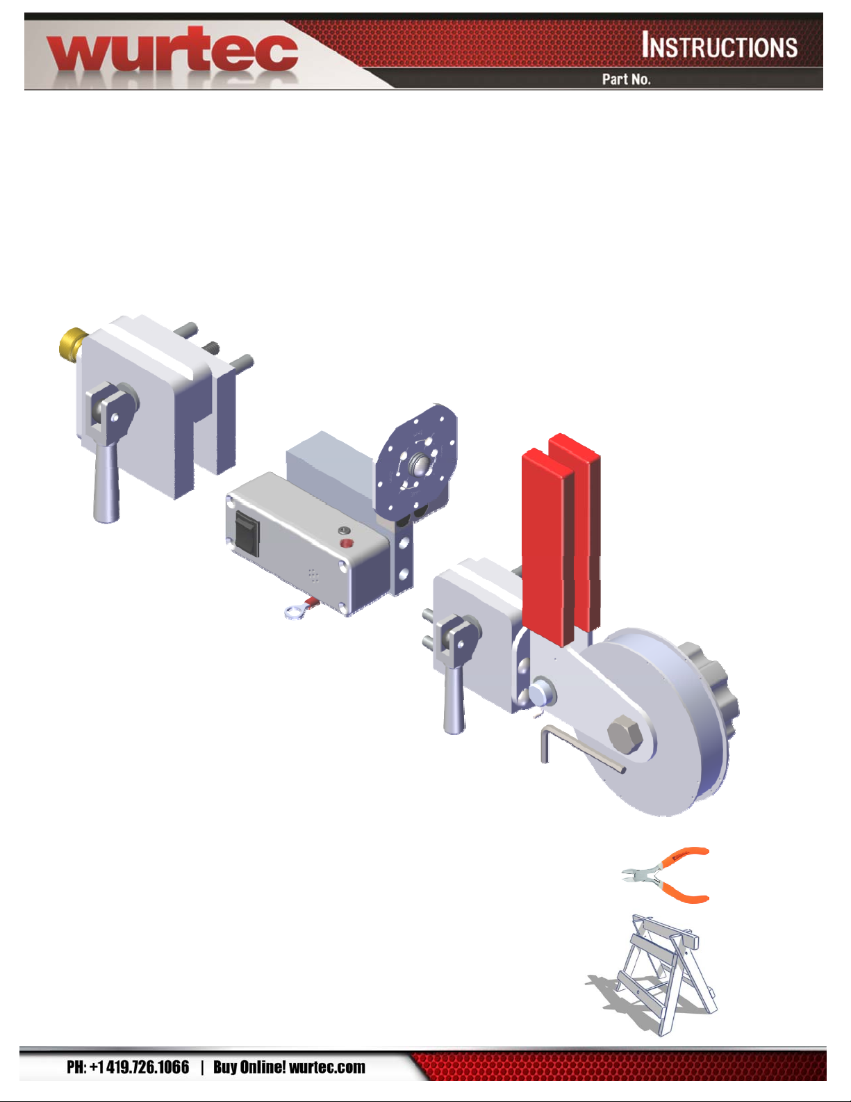
Description .........................................................................................................................................................4
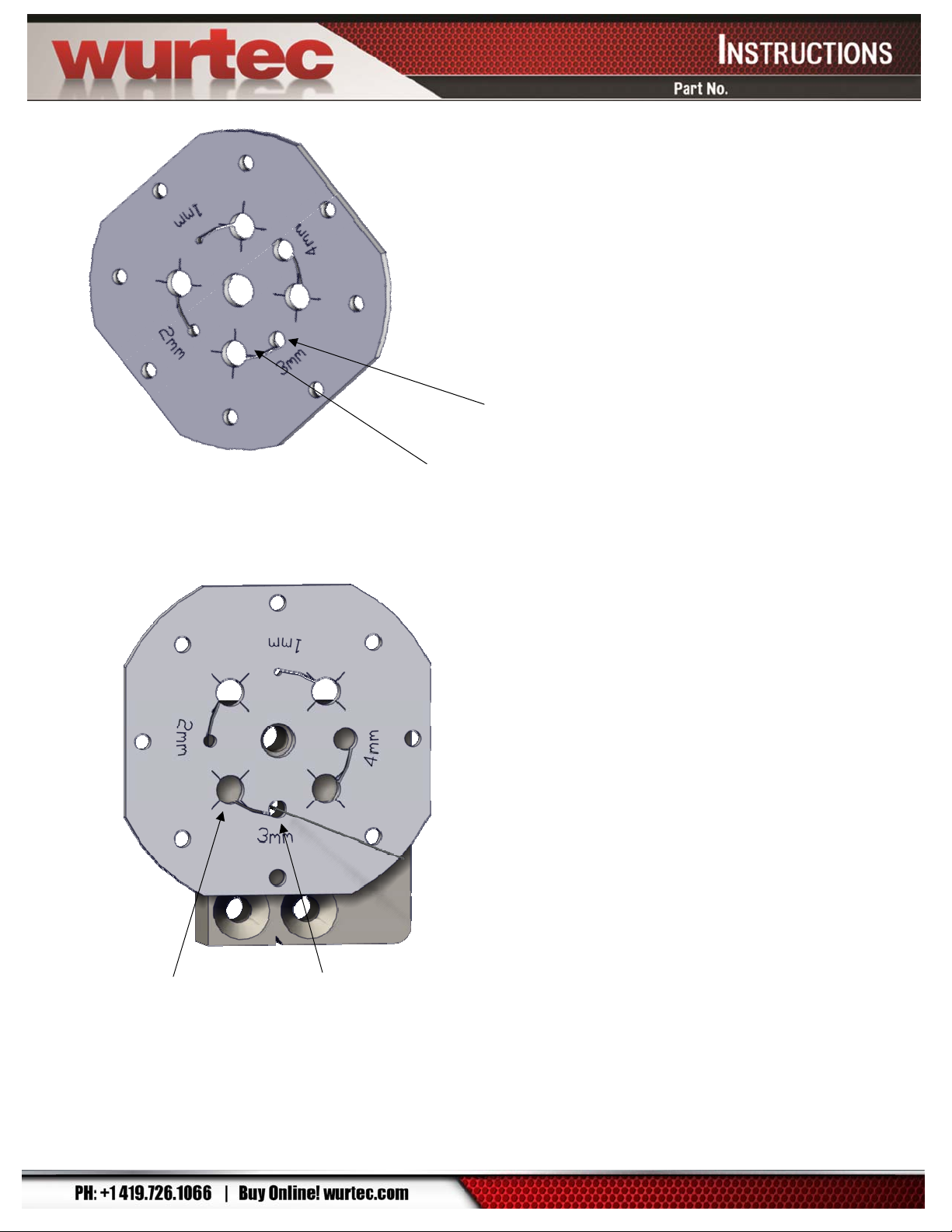
Features and Functions.....................................................................................................................................5
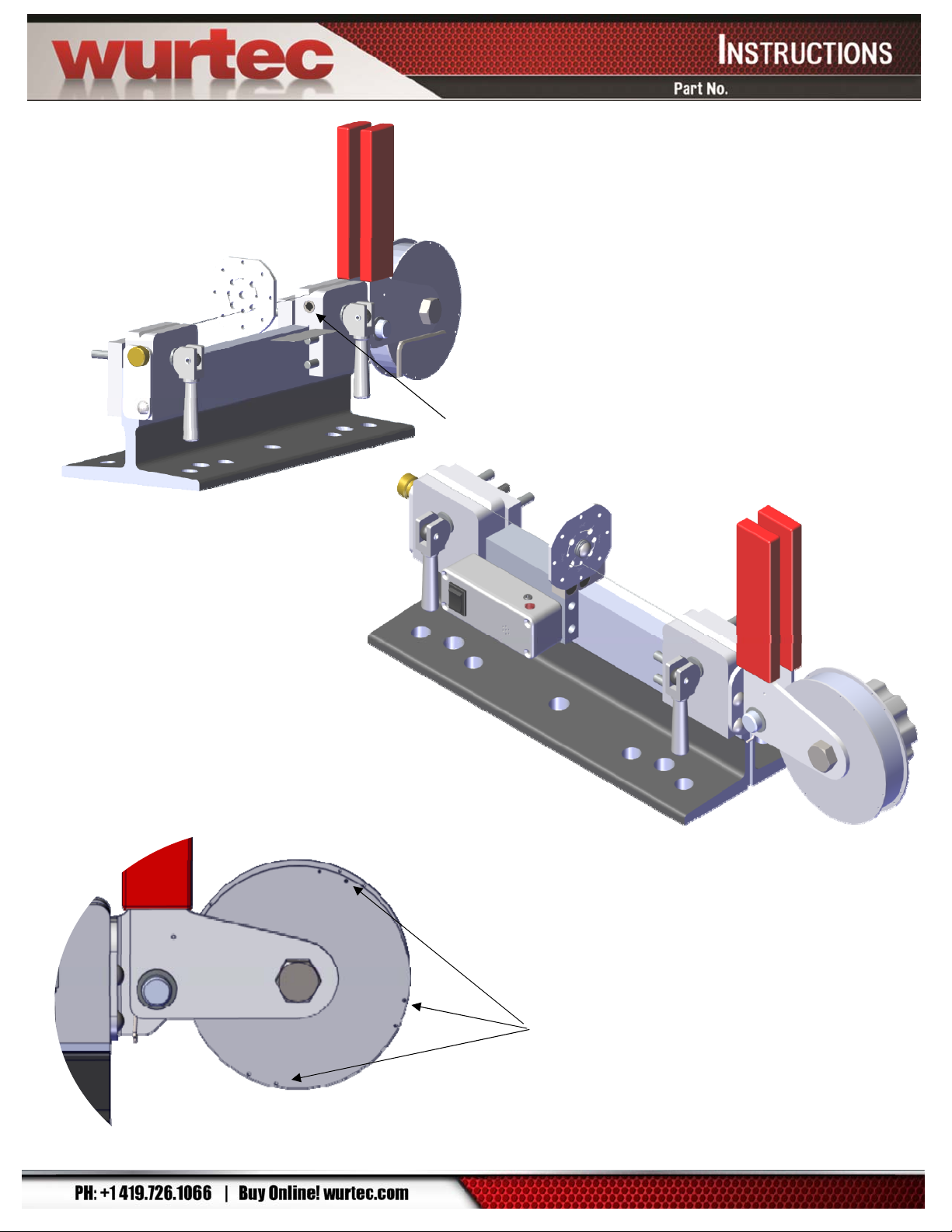
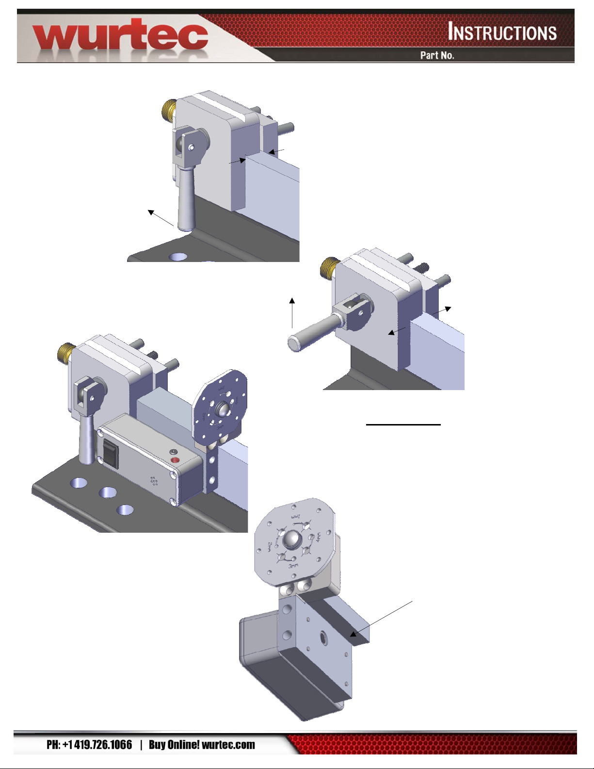
Set Up..................................................................................................................................................................9
1. Rail Set Up ...............................................................................................................................................9
2. Rail Straightness Tester Set Up.............................................................................................................9
a. Rail End Clamp...............................................................................................................................10
c. Rail End Clamp (with Spool Assembly) .......................................................................................11
d. Steel Wire Installation....................................................................................................................11
Testing and Operation.....................................................................................................................................13
Troubleshooting...............................................................................................................................................14
Replacement Parts.......................................................................................................................................14
Bill of Materials.................................................................................................................................................15
Rail End Clamp 30-10001686...........................................................................................................................15
Exploded View..........................................................................................................................................15
Parts List...................................................................................................................................................15
Sensor Block 30-10001673..............................................................................................................................16
Exploded View..........................................................................................................................................16
Parts List...................................................................................................................................................16
Rail End Clamp 30-10001698...........................................................................................................................17
Exploded View..........................................................................................................................................17
Parts List...................................................................................................................................................18