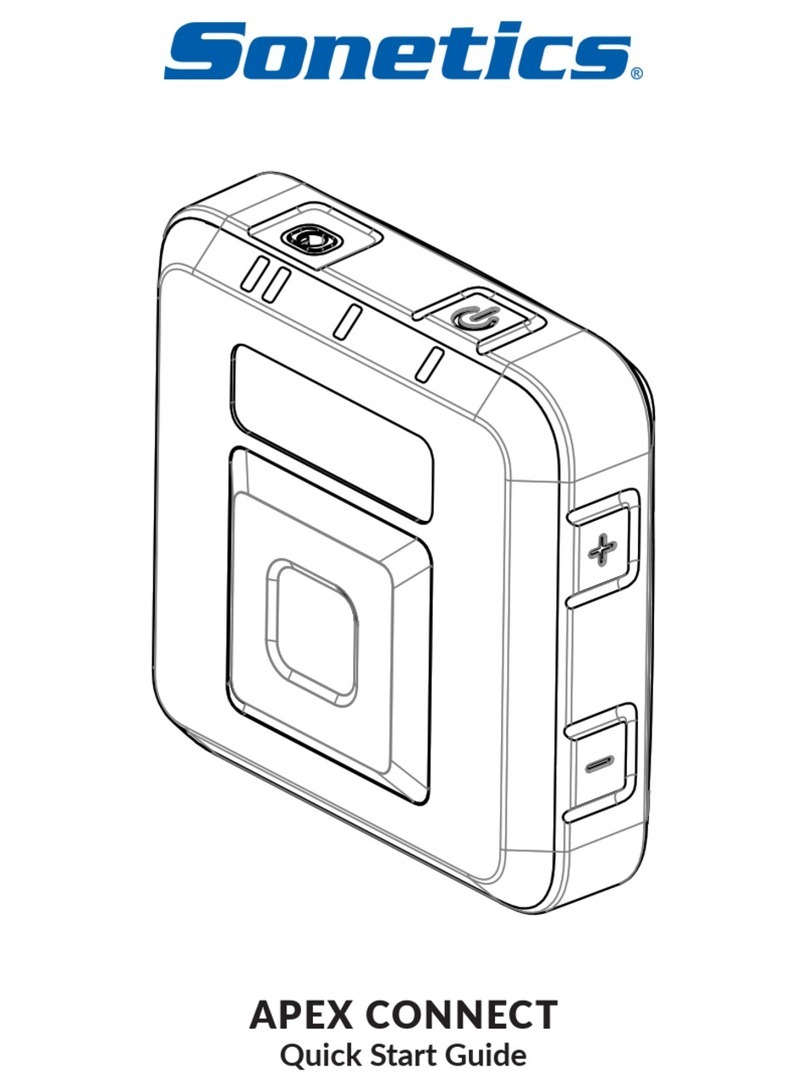
Sonetics APEX CONNECT User manual

APEX CONNECT
Manual

Table of Contents
Overview 1
Contents in Box 1
Accessories (not included) 1
Features 2
Common Features 2
Wireless Bluetooth® Technology 2
Wireless DECT7 Communications 2
Pick Your Headset (or Bluetooth Speaker) 3
Wear or Mount Your Apex Connect 3
Charging 4
LED Indications 5
Settings & Operation 5
Buttons 5
Wireless Bluetooth® Pairing 6
Wireless DECT7 6
Advanced Menu & Quick Launch 7
Quick Launch Menu Options 8
Channel Mode 9
Broadcast Only Pairing 9
Headset to Multi-Base Station 10
Firmware Updates & PC Programming 11
USB Port Location 11
Updating Firmware for your Apex Connect 11
Care and Maintenance 12
Troubleshooting 12
Service Contact 12
General Connection Issues 12
Wireless Bluetooth 12
Wireless DECT 12
Specifications 13
Important Safety Information 15
General Warning for Sensitive Electronic Devices 15
General Communication Privacy Notice 15
Industry Canada (I.C.) Notice (APX-CONNECT) 15
FCC Part 15 Information (APX-CONNECT) 16
FCC/IC RF Exposure Warning 16
Rechargeable Battery Information 16
Sonetics Standard Limited Warranty 17

1 | Page
Overview
The Sonetics Apex Connect allows users in low noise environments to connect with
their teams in high noise environments without having to wear a hearing protection
headset. Users simply leverage their existing corded wired headset or Bluetooth®
headset to plug or pair to the Sonetics Apex Connect to communicate with their team
up to 800 feet line of sight, hands-free. The Sonetics Apex Connect is rugged and
rated at IP67, so it’s waterproof and portable to different environments.
Contents in Box
APEX Connect
1 ea x Apex Connect
Manual and Reference
1 ea x Quick Start Guide
1 ea x Manual (online at: www.soneticscorp.com)
1 ea x FCC / IC / NRR compliance sheet
1 ea x Warranty Card
Charging
1 ea x AC USB Wall Adaptor
1 ea x USB-C charging cable
1 ea x DC Charging Adaptor
Accessories
1 Connect Magnetic Belt Clip
1 Round Magnet Clasp
Accessories (not included)
Wired Headset
Bluetooth Headset (or ear buds)
Bluetooth Speaker
Connect Belt Pouch
USB Charging Hub

2 | Page
Features
Common Features
Adjustable Volume Control
The Apex Connect has a user adjustable volume control. For convenience, the Apex
Connect will remember the last setting each time it is turned on.
Rugged Environmental Design
The Apex Connect has an IP-67 dust and water egress rating. Operation has been
verified to -22F / -30C for extreme cold weather environments.
Discrete Size
At a mere 3” x 3” x 1”, the Sonetics Apex Connect is discrete in size to be worn on
your belt clip, clipped to your clothing, or slipped into a pocket.
Flexible Charging
A USB-C charging cable can be used with either the supplied USB AC wall adapter or
DC charging adapter.
Portable and Light Weight
Through the use of the latest weight savings technologies Sonetics is able to deliver
a communication device weighing 5.8 ounces in a mere 3” x 3” x 1” enclosure.
Long Battery Life
With over 24 hours of battery life the Connect works whenever the user needs it.
Device Mute
Users can mute all outbound communication from the Apex Connect. With a simple
button push full communication is restored.
Auto Shutdown
To extend the life of the batteries, the Apex Connect will automatically shut down.
DECT7 Wireless Shutdown: If a DECT wireless connection has not been established
in 10 minutes, the Connect will power down.
Low Battery Alert
Your Apex Connect has a critically low battery of 5% or less when the Power LED is
flashing red.
Auto Noise Gate Setting
The Apex Connect is equipped with an Auto Noise Gate setting which automatically
sets the noise gate for you based on what is heard from the device microphone. The
Auto Noise Gate setting is continuously working to keep background noise out of the
system. If you find a specific noise gate setting is preferred, users can choose their
own fixed noise gate setting from the Advanced Menu.
USB Programmable
Using the USB port, the Apex Connect can be updated using a Windows PC. Refer to
the section on updates for details.
Voice Prompts
Voice prompts allows the user to make all adjustments without removing the headset
or device you are using. There is no need to look for lights, text, or knob positions.
Radio Push-to-Talk (PTT)
When a two-way radio is interfaced into a Sonetics ComHub and the Apex Connect
has DECT pairing, the PTT button press passes the signal to the wireless DECT7
Wireless Base Station.
Wireless Bluetooth® Technology
Apex Connect incorporates Bluetooth for users to pair their preferred device to the
Apex Connect for continuous conference call like communication with their team.
Users can pair Bluetooth headsets, ear buds, and speakers to their Connect.
Wireless DECT7 Communications
The Apex Connect enables full duplex, conference-call-like communications to others
on the same channel. The Apex Connect will pair to stand alone Sonetics Wireless
Base Stations or Sonetics IP-DECT7 wireless systems. The Apex Connect provides up
to 800ft of range (line of sight) from its wireless base with interference free, digitally
encrypted communications.
Backwards Compatibility
Apex Connect devices are backwards compatible with Sonetics first generation
wireless DECT, and DECT6 Wireless Base Stations with minimal loss in functionality.
Broadcast Mode
The Apex Connect may be paired into a listen only mode of operation, reducing
power consumption considerably. This also allows many more Apex Connects or
headsets to be connected to a Wireless Base Station simultaneously. Pressing the
Radio PTT button allows the Apex Connect or headset to momentarily talk on any

3 | Page
available slot. A tone will let the user know when they can talk. After talking, there
will be a slight delay when other users cannot be heard. Refer to the Wireless Base
Station manual for details.
Radio PTT or Intercom Only Selection
The Apex Connect may be configured to send a transmit signal to radios connected
via a DECT7 Wireless Base Station or Intercom. The user can transmit over multiple
radios depending on the configuration.
Multi-Channel System
Depending on the wireless DECT7 Wireless Base Station or IP-DECT7 system, the user
may have access to multiple channels. This allows large teams to have separate
channels for different activities and enables users to change channels and become
one communication team. Refer to the Wireless Base Station manual for
configuration details.
Out of Range Warning
The user is notified when DECT7 signal is weak, or when it goes out of range.
Proximity Pairing
To enhance security, the Wireless Base Station will only pair to wireless DECT7 units
in close proximity. This adds another layer of protection for users.
Signal Strength Reporting
The Apex Connect may be placed into a field diagnostic mode to detect signal
strength at the Apex Connect. This can be used to optimize placement of ComHubs
or Base Stations.
Wide Band Audio
Wireless DECT7 communications are transmitted in a high-definition wide band audio
format. This gives better sound quality, greater intelligibility, and improves with voice
activated control systems. The Apex Connect can also be used in narrow band if
necessary.
Multi-Base Station Mode
Allows users to pair their Apex Connect to multiple Base Stations at once so users can
switch to a different Base Station without having to perform the DECT pairing
function each time.
Configuring the Apex Connect
The Apex Connect can be used in a variety of ways including being placed on a desk,
worn on your belt with the included magnetic belt clip, clipped to your clothing with
the round magnetic clasp or simply dropped into your pocket. Already have a
magnetic mount? You can use those too. Users even have many options of what type
of device they choose to use with their Apex Connect like Bluetooth headsets,
Bluetooth ear buds, Bluetooth speakers/conference call speakers or a 3.5mm wired
headset.
Pick Your Headset (or Bluetooth Speaker)
Wear or Mount Your Apex Connect

4 | Page
WARNINGS:
Magnets can pinch and break bones. Use extreme caution when handling
magnets to avoid magnets snapping or slamming together. Do not put hands,
fingers or any other body parts between magnets.
Use caution to keep magnets at a safe distance from metals, steel and other
magnets to avoid instant impact, splintering or breakage.
Magnetic fields, especially those produced by rare earth magnets, can affect
pacemakers and other implanted medical devices. Extreme care should be
taken to keep magnets away from these devices to avoid deactivation. Please
consult a medical professional if there are any questions regarding an
implanted device and magnets.
Charging
The Sonetics Apex Connect uses a USB-C charging jack with the connections shown
below.
Note: Prior to first use, make sure to charge your Apex Connect to full charge.
Vehicle Charging
Use the supplied USB-C charging cable and DC automotive charging adapter.
Wall Adapter Charging
Only charge the Apex Connect using a regulated USB A wall adapter, 5V 1A
minimum. Apex Connect will be fully charged after 4 hours.
Charge Status
When plugged in, the color of the Power LED indicates the charge status.
Fully charged
Charging
Battery Levels
WARNING: Using unregulated wall adapters will damage the Connect and
void the warranty.

5 | Page
LED Indications
The Apex Connect uses multicolor LED indicators to give additional information on
the exterior of the device. The table below describes the behavior while charging or
in use.
LED Status Lights (blinking/solid)
DECT Pairing/reconnecting
DECT Paired
Bluetooth Pairing/reconnecting
Bluetooth Paired
Mic Device Mute ON
Mic
Radio transmit or Intercom
On/Toggle transmit
Settings & Operation
Buttons
Turn On
Apply a 1 second short Power Button press to turn ON the device.
Turn Off
Apply a 1 second short Power Button press to turn OFF the device.
Adjusting the Main Volume
Press the plus or minus –buttons on the side of the Apex Connect.
Adjustments to the volume can also be made on the device paired or plugged into
the Connect.
Device Mute
This feature blocks all outbound communication from your device.
With Apex Connect power ON and your headset plugged in or paired via Bluetooth
1. Press and hold the minus –for a 2 second long button press.

6 | Page
2. System is Muted when the Red Mic LED is alternately blinking on and off
quickly.
3. Press and hold the minus –button again or press and release the PTT
button to turn OFF the Device Mute feature.
PTT Button
The large square button on the front of the Apex Connect allows for communication
over two-way radios via PTT (and intercom operation in Intercom PTT and Intercom
Toggle modes).
Simply press and hold the PTT button on the Apex Connect to communicate over
the two-way radio frequency connected to your ComHub.
Wireless Bluetooth® Pairing
1. Turn ON your Bluetooth device.
2. Turn ON the Apex Connect.
3. Make sure your Bluetooth device is in
pairing mode (follow your
manufacturer’s instructions).
4. Put the Apex Connect into pairing mode
by simultaneously pressing PTT and
plus buttons, then hold for 2 seconds
and release. The Bluetooth LED will be
blinking blue.
5. Pairing successful when Bluetooth LED is
solid Blue.
Notes:
•Bluetooth pairing will timeout after 40 seconds.
•When a corded headset is plugged in, Bluetooth turns off.
•Bluetooth headsets (or other Bluetooth devices) will connect to other Bluetooth
devices they have previously paired to. Ensure your Bluetooth device you are
using with the Apex Connect “Forgets” these other devices. The easiest way to
achieve this is to reset the headset.
•Apex Connect only remembers the last device it was paired to.
•The pairing command clears the previous pairing
•SCH305-BT ComHubs can Bluetooth pair to Apex Connects in Bluetooth pairing
mode. Make sure your SCH305-BT ComHub is powered OFF while you are
Bluetooth pairing your Bluetooth headset to the Apex Connect.
Wireless DECT7
DECT7 Apex Connect devices have the ability to use the Sonetics DECT, DECT6, DECT7
and IP-DECT7 wireless Base Stations for communication. Protected regional
frequencies in each region ensure interference free operation.
DECT7 Pairing
DECT7 Wireless Apex Connect devices use a semi-permanent link to a DECT7 Base
Station or IP-DECT7 system. No additional steps are required once a Connect has
been paired. Each time thereafter, the Apex Connect will remember the Wireless
Base Station and automatically reconnect.
To Create a New DECT Pairing
1. Place Base Station into pairing
mode (see base station manual for
details.)
2. With the Apex Connect powered
on, simultaneously push and hold
the Power and PTT buttons
for 2 seconds, then release. The
DECT LED light will
blink green
while pairing.
3. The LED will be solid green when
connection is successful. If it does
not, repeat the pairing process.
Note:DECT paring will timeout after 40 seconds.
Out of Range Warning:
•If Apex Connect has low radio signal (RSSI) to its Base Station it will report “DECT
Radio Level Low”.
•If Apex Connect loses signal to the base station it will report “Base station
Disconnected”.
•If Apex Connect regains signal to the base station it will report “Base station
Connected”.
•If device is not connected to a base station it will power down after 10 minutes.

7 | Page
Advanced Menu & Quick Launch
The Advanced Menu is to set-up and configure the Apex Connect for use. Caution
must be taken with these adjustments, as they change the operational characteristics
of the Apex Connect.
To Enter the Advanced Menu
While the Apex Connect is ON, simultaneously press and hold the plus and
minus –and Power buttons until you hear “Advanced Menu” voice prompt.
To Adjust Advanced Menu settings
1. Enter the Advanced Menu.
2. Press either the plus or minus –to cycle through the menu setting options.
3. Once you hear the menu setting item you want to change, press the PTT
button to select the menu item
4. Again, press either the or minus –button to cycle through the settings
and press the PTT button to confirm your selection. You will hear a “Set”
voice prompt.
5. Press the Power button to go back to change a different setting or keep
pressing the Power button to exit the Advanced Menu. You will hear a
“Exiting Advanced Menu” voice prompt.
To Exit the Advanced Menu
Press the Power button until you hear the “Exiting Advanced Menu” voice prompt
or wait 15 seconds to automatically exit.
Advanced Menu Structure & Settings
•Version
•Radio / Intercom Modes
•Mic Noise Reduction (Noise Gate)
•Bluetooth Mic Gain
•Corded Mic Gain
•Corded Side Tone
•DECT Radio RSSI Reporting
•DECT Audio
•DECT Registration
•DECT Multi-Base Station
Version ("Version 1")
Indicates what firmware version your Connect is running.
From this menu item users can enter “Factory Options” settings, which allows for
the following:
•“Default Settings” – when selected Apex Connect is reset to default settings
(DECT and Bluetooth pairings remain).
•“Factory Reset” - when selected Apex Connect clears all DECT pairings,
Bluetooth pairings, and resets to default settings.
Radio / Intercom Modes
Sets the function of the PTT and Intercom.
Radio Transmit: For Radio PTT, when the Apex Connect has a DECT connection, and
a two-radio interfaced into the ComHub, the PTT may activate the DECT Radio
wireless connection.
Intercom: This configures how the PTT and Mic Noise Reduction (Noise Gate) interact
with each other while a person is talking with their local wireless team. If you can
hear yourself through the side tone, others can hear you.
Factory Setting
Options:
“Radio VOX”:
Radio Transmit
on PTT
,
Hands Free
Intercom
•“Radio VOX”: Radio Transmit on PTT
, Hands Free
Intercom
•“Radio PTT”: Radio Transmit on PTT , Push to Talk
Intercom
•“Intercom VOX”: Hands Free Intercom only
•“Intercom PTT”: Push to Talk Intercom only
•
“Intercom Toggle”:
Toggle to Talk Intercom only
Mic Noise Reduction (Noise Gate)
Factory Default: “Auto”
The Mic Noise Reduction may be configured into multiple modes of operation to
tailor to the user’s application. This setting allows adjustment of the mic attenuation.
Higher numbers reflect a more aggressive noise gate, which makes background noise
harder to be heard. The “Auto” setting works continuously to automatically select
the optimum setting for the user based on the audio level received from the mic.
However, the user can choose a “Fixed” setting (from 1 minimum to 9 maximum) if
they choose. Also, “Off” can be selected, resulting in no noise gate.

8 | Page
Notes:
•When using Bluetooth ear buds, a setting of 2 or lower is recommended.
•When the user presses the Radio PTT, any noise gate will be removed when in
Radio VOX & Radio PTT modes.
Bluetooth Mic Gain
Factory Default: “4”
Allows adjustment of the mic amplitude for your Bluetooth device. If Bluetooth
device controls separately will use those settings. Normally, adjustment is not
needed.
Available Settings: 0 – 15 (0 is minimum, 15 is maximum)
Corded Mic Gain
Factory Default: “6”
Allows adjustment of the mic amplitude of your corded device. Normally, adjustment
is not needed.
Available Settings: Minimum, 1 – 7, Maximum
Corded Side Tone
Factory Default: “ON”
Side Tone is the ability to hear yourself talking, if you can hear yourself then others
on the system can hear you too.
Available Settings: ON / OFF
DECT Radio RSSI Reporting
Factory Default Setting: “OFF”
Enabling this setting allows the Connect to read out RSSI (Received Signal Strength
Indicator) numbers that tell you how strong the connection to the Base Station or
ComHub are. This can be used to improve system installations.
To use signal strength reporting:
1. Make sure your Connect has a DECT wireless connection.
2. Enter the Advanced Menu.
3. Use the plus or minus –buttons to scroll through settings until you hear "Radio
RSSI Reporting".
4. Press the PTT button to enter the available settings
5. Use the plus or minus –buttons to change the setting to "ON" or “OFF”.
6. Press the PTT button to confirm your desired setting. You will hear the “Set”
voice prompt.
7. If the Apex Connect has a DECT connection and the Radio RSSI Reporting is set to
ON, it will announce the signal strength every 5 seconds. If no DECT connection is
present, the Apex Connect will announce “No DECT” once.
To exit, press the Power button until “Existing Advanced Menu” voice prompt is
heard.
DECT Audio
Factory Setting
Options:
“DECT Wide”
•“DECT Wide" – Better sound quality.
•
“DECT Narrow” – Better resistance to interference.
DECT Registration
Factory Default: “ON”
Allows device to be DECT paired to other base stations. Can be set to “OFF” to
prevent accidental unpairing during normal use.
DECT Multi-Base Station
Factory Default: “OFF”
Allows users to pair their Apex Connect to multiple Base Stations at once so users
can switch to a different Base Station without having to perform the DECT pairing
function each time.
Quick Launch Menu Options
Quick Launch allows for users to access some features quickly without having to go
into the Advanced Menu to make adjustments after they are enabled from the
Advanced Menu the first time. (For example, Channel selection and Multi Base

9 | Page
Station selecting can be made with having to repeatedly accessing the Advanced
Menu).
Button Press
Voice Prompt
Advanced Menu
Plus
Minus
–
Power
“Advanced Menu”
Quick Launch –
Channel Mode Quick plus & minus –“Channel”
Quick Launch –
Multi Base Mode Long plus & minus –“Multi-base[X]”
Channel Mode
The APEX Connect can be used in Channel Mode by enabling Channel Mode on the
Base Station. Up to 5 channels are available through the Wireless Base Station when
used in this configuration. Follow the steps below to configure your Base Station.
Note: The Base Station needs to be put into Channel Mode for the Apex Connect to
recognize the Quick Launch command.
Setting the number of channels on your Base Station
To enter configuration mode:
1. Unplug the Base Station (or cycle power on your ComHub, then plug it back in
while holding the position 3 pairing button on the Base Station.
2. Hold the pairing button until the green channel indicator LED turns on.
3. The Base Station is now in ComHub mode.
4. To set the number of available channels, press the pair button corresponding to
the number of channels desired (button 2 = 2 channels, etc). The current number
of channels is shown with a green LED on the associated Mode/Channel Indicator
(e.g. Port 5 = 5 channels).
5. To exit configuration mode, unplug your Base Station (or cycle power on your
ComHub) from power, then plug it back in. The Base Station is now ready to use.
Setting up the APEX Connect for Channel Mode:
Now that your Base Station is set up in Channel Mode, your APEX Connect Quick
Launch-Channel Mode function is enabled. To change between your desired Channel:
1. Quick press the plus and minus –buttons simultaneously and release. You will
hear the “Channel” voice prompt.
a. If you do not hear the “Channel” voice prompt, simply retry the step 1.
2. Use the plus or minus –buttons to select your desired channel.
3. Once you hear the desired channel voice prompt, repeat Step 1. You will hear the
“Channel Exiting” voice prompt. (Pressing Power also exits Channel Selection.)
Notes:
•To switch between the different Channels, repeat the Quick Launch-Channel
Mode steps
•If you do not Exit the Quick Launch-Channel Mode, you will not be able to adjust
your Apex Connect volume. Simply perform the Quick Launch button press and
you will Exit the Quick Launch.
Broadcast Only Pairing
Note: Broadcast Mode needs to be enabled on the Base Station first. Follow the steps
below.

10 | Page
Broadcast Only allows up to 100 devices to be paired to a Base Station. One active
full duplex pairing must exist for the Broadcast Channel to be opened. Broadcast
users never have Radio Transmit capability.
Example: Position 1 has a Full Duplex Apex Connect (or Headset) pairing. Positions 2-
4 are available for devices to share. Position 5 broadcasts back to the group.
1. Press and hold Buttons 4 & 5 on the Base Station until 4 & 5 link LEDs begin to
flash slowly.
2. Place the Apex Connect or wireless headset you wish to link into pairing mode.
3. The wireless Base Station will automatically connect showing a solid link LED on
position 5 and the device will show connected (refer to the Sonetics device
manual).
4. If the pairing was unsuccessful, repeat steps 1-3.
5. To pair additional devices, repeat steps 1-4.
Because Broadcast Only Apex Connects and headsets share communication
positions, there can be slight delays in communication. To talk, the PTT button
must be held until a position opens. After a Broadcast call is made, there will be a
pause in which incoming communications cannot be heard.
To exit Broadcast Only mode:
Press and hold 4 or 5 until the link LED flashes slowly indicating pairing mode.
Headset to Multi-Base Station
What is Headset to Multi-Base Station?
In normal operation, an Apex Connect (or headset) may only pair with a single Base
Station. The Headset to Multi-Base Station feature allows a user to pair any Apex
Connect (or APX377 or APX379 headset) DECT7 Wireless device with up to four
SON150 DECT7 Wireless Base Stations.
Before You Begin: Clear All Pairings on the Base Station
Follow these steps for each Base Station to which a Headset to Multi-Base Station
user(s) will be paired.
1. Make sure any Apex Connect (or headsets) paired to the Base Station are powered
off before you begin.
2. To clear pairings, follow these steps:
a. Power ON the Base Station or ComHub (For a SON150, connect the power
adapter to the Base Station and plug the adapter into a standard 120V wall
outlet. If the Base Station is installed in an SCH305/310/310T ComHub, press
and release the ComHub’s power button).
b. When all paired Apex Connect (or headsets) are turned off, any position on
the Base Station with an active pairing to an Apex Connect (or headset) will
display a quick flashing yellow LED above the corresponding pairing button.
If you see a steady yellow LED, the Apex Connect (or headset) paired in the
position is turned on. Turn the Apex Connect (or headset) OFF before
proceeding.
c. Press-and-hold the pairing button on the Base Station until it displays a slow
flashing yellow LED.
d. Power OFF the Base Station or ComHub.
e. Power ON the Base Station or ComHub and confirm that no yellow LED is
visible above the position button.
f. The pairing is now cleared. Repeat Steps 2a-2e to clear each additional pairing
from the Base Station. Perform this sequence for ALL Base Stations to which
they will be eventually paired to.
Enabling and Configuring the Apex Connect to Multi-Base Station Mode
To enable and configure the Apex Connect to Multi-Base Station mode, access the
Advanced Menu on your Apex Connect:
1. Refer to the Advanced Menu section in this manual for accessing the Advanced
Menu.
2. Scroll through the Advanced Menu until you hear the “DECT Multi-Base Station”
voice prompt, then press the PTT button to confirm the selection.
3. Use the plus and minus –buttons to select the number of Base Stations the
Apex Connect will pair to. For example, “2 Base Stations”.
4. Press the PTT button to confirm your selection, you will hear a “Set” voice
prompt.
5. Use the Power button to Exit the Advanced Menu.
Pairing the Apex Connect to Base Stations for Use in Multi-Base Station
Mode
1. Use the Quick Launch-Multi-Base Station command on your Apex Connect to
select the number Base Station you want to pair to by:
a. Use a long press of the plus and minus –buttons at the same time, then
release quickly. A “Multi-Base” voice prompt will be heard.
b. Use the plus and minus –buttons to select the desired Base Station
number, then press the PTT button to confirm the selection.
2. Put the selected Base Station into pairing mode by pressing and holding the
desired position pairing button until the yellow LED flashes.

11 | Page
3. Put the Apex Connect into DECT pairing mode. You will hear a voice prompt: “Base
Station 1 connecting”.
4. The DECT pairing is complete when the DECT LED on the Apex Connect changes
from blinking green to solid green.
IMPORTANT: Pair any additional Apex Connects that will use the Headset to Multi-
Base Station feature to Base Station 1 before you begin any pairings on Base
Station 2, etc. This will ensure that all Multi-Base Apex Connects recognize Base
Stations by the same number.
5. Now that you have all Apex Connect devices (or headsets) paired to Base Station
1, turn OFF the Apex Connect’s (or headsets) and Base Station 1.
6. Turn ON the next Base Station (for example, Base Station 2).
7. REPEAT Steps 1-4 for each additional base station until all are paired (up to 4 Base
Stations).
Selecting a Base Station in Multi-Base Mode
After all Base Stations have been set up, you can use the Quick Launch-Multi-Base
Station command to flip between the available Base Stations by:
1. Using the Quick Launch-Multi-Base command: Using a long press of both the plus
and minus –buttons simultaneously then releasing quickly. You will hear the
“Multi-Base” number voice prompt.
2. Use the plus and minus –buttons to select the Base Station you wish to
connect to (Voice prompts will announce “Multi-Base 1”, “Multi-Base 2” (up to
four paired Base Stations).
3. Press the PTT button confirm and exit.
The Apex Connect (or headset) will connect with the selected Base Station. When/if
you move out of range of the connected Base Station, the Headset will lose its
connection. To select a different Base Station, repeat steps 1-3 above.
Firmware Updates & PC Programming
The Apex Connect can be updated with the latest firmware via the USB port with the
following steps:
USB Port Location
Updating Firmware for your Apex Connect
Note: The firmware file will need to be downloaded and saved to your computer from
the Sonetics website prior to performing the steps below.
1. Turn Apex Connect OFF
2. Hold Power on button for approximately 10 seconds
•Power LED will red slow flash, continue holding until flashes quickly to
indicate it's in bootloader mode
3. Plug USB-C cable into Apex Connect and PC
4. In File Manager Apex Connect will appear as an extra drive (normally D :)
5. Select ALL the files in the Apex Connect D drive and delete all of them.
6. Drag and Drop or Copy and Paste ALL the update files you downloaded from
the Sonetics website onto the Apex Connect drive
•Files will copy over. Apex Connect will flash yellow as it is transferring over
files and updating its libraries.
i.Example file names (not limited to):
1. bp_490-4071-00.sonbin (firmware)
2. config_[SKU]_490-4036-01.bin (Settings (not pairing))
3. vp_490-4039-00.sonbin (Voice prompt file)

12 | Page
•If you get an “Error” message, you need to delete the existing files on the
Apex Connect, before you can add the new update files.
•Once complete the Power LED light will flash Green, and then return
to Red quick flash indicating it's waiting.
•Apex Connect will repeat for each file copied into the Apex Connect drive.
•It's important ALL update files are transferred before rebooting.
7. Once all files are updated, hold the Power button ~2 seconds until system
reboots.
8. System will come up in normal operation.
9. You can disconnect Apex Connect from your PC.
Note: When update is complete, existing settings will be reset to factory defaults.
Bluetooth and DECT pairings will remain.
Care and Maintenance
•Inspect your Apex Connect frequently for wear. If you see any defect such as
cracks on the enclosure, the Apex Connect should be immediately repaired or
replaced.
•Wipe the Apex Connect with a mild soap and water mixture or a hydrogen
peroxide-based wipe.
WARNING: Do not store the Apex Connect in high temperature environments
or direct sunlight.
Troubleshooting
If you are experiencing symptoms not covered here, or are having difficulty
troubleshooting, call us or visit our website. We’re here to help.
Service Contact
800-833-4558
General Connection Issues
1. Verify the Apex Connect is turned on.
2. Verify the battery is charged and within its useable life.
Wireless Bluetooth
Disconnects, intermittent connectivity, or difficulty finding, pairing, or
connecting.
1. Verify your Bluetooth headset model are Bluetooth compatible (Handsfree Profile
Format required).
2. Check that you are in range of the Bluetooth accessory with which you are trying
to pair your Apex Connect.
3. With multiple Apex Connects & Bluetooth headsets, ensure devices are dedicated
to each other.
4. Apex Connect deactivates Bluetooth when a corded headset is plugged in.
5. Turn on Bluetooth on your device.
6. Turn on discoverable mode on your device.
7. Make sure no previously paired devices are turned on.
8. Cycle the power on the Bluetooth headset and/or the device being connected to.
9. Fully charge both the Apex Connect and your headset.
10. Noisy RF Environments can reduce effective Bluetooth range (including walls,
microwaves ovens, Wi-Fi, etc.), ensure you remain as close as possible to your
Apex Connect.
11. While pairing, ensure the Bluetooth headset is the closest device to Apex
Connect. When pairing, your Bluetooth device must be within 1-3 feet of the
Apex Connect.
12. Restart the Bluetooth pairing mode, this will delete the Bluetooth headset from
your Apex Connect and create a new pairing.
13. Factory reset your Bluetooth headset to forget previous device pairings.
14. Update your Bluetooth device to the latest Bluetooth firmware.
15. SCH305-BT ComHubs’s can Bluetooth pair to Apex Connects in Bluetooth pairing
mode, make sure your SCH305-BT ComHub is powered OFF while you are
Bluetooth pairing your Bluetooth headset to the Apex Connect.
Wireless DECT
Disconnects, intermittent connectivity, or difficulty finding, pairing, or
connecting.
1. Check that you are in range of the DECT Wireless Base Station, and that it is
powered on.
2. Verify the Wireless Base Station and the Apex Connect are in pairing mode.
3. Verify the Apex Connect has DECT Registration enabled (Advanced Menu).
4. If DECT is not connected for 10 minutes, Apex Connect will power down to save
battery. Any button press delays the power down timer.
5. Cycle the power on the Apex Connect and/or the Wireless Base Station.
6. Fully charge both the Apex Connect and the ComHub (or ensure the Wireless Base
Station is plugged in).

13 | Page
7. Check location of the Wireless Base Station and external antenna location. The
Wireless Base Station should not be installed inside metal enclosures or any other
location closer than 4 inches to a metal object or surface.
8. When reconnecting to a Base Station, you may need to reset the DECT pairing
slot.
No audio communication and/or PTT from or to the base.
1. Ensure that power is turned on to the Wireless Headset and it is connected.
2. Ensure that the modular communication cable is connected between the Wireless
Base Station and Intercom.
3. Check the modular communication cable between the Wireless Base Station and
Intercom for continuity.
4. Ensure correct polarity of the modular plug on both ends of the modular cable.
5. Ensure the corded headset follows standard 4-pin plug (CTIA/AHJ or OMTP), or
use appropriate adapter.
6. Verify the Apex Connect radio settings, ensure you are using the correct mode
(Advanced Menu).
7. Ensure Mic Noise Reduction is set appropriate for environment (Advanced Menu).
Poor quality audio, low or distorted received or transmitted audio.
1. Make sure that the volume level is properly adjusted on the Intercom (if an
intercom is installed). For Digital Intercoms, set the volume level as high as
possible on the Intercom without causing distorted audio on the Apex Connect,
and then adjust the volume control on the Apex Connect for comfortable
listening.
2. Ensure that the proper Wireless Base Station model for your Intercom is used.
3. Power cycle the Base Station.
4. Noisy RF environments can reduce effective Bluetooth range (including walls,
microwaves ovens, wifi, etc.).
5. Bluetooth HFP (Hands Free Protocol) connections slightly increases audio latency.
6. Poor quality audio can be caused by a defective headset device. Confirm
operation with a headset known to be functioning properly.
Audible interference from portable and mobile radios.
The wireless system is tested and proven to be immune to interferences from
portable and mobile communication equipment operated anywhere in the frequency
spectrum from 30MHz to 18GHz. However, care should be taken with installation of
communication cables between the Intercom and the Wireless Base Station. These
cables should be routed away from portable and mobile radios and antenna cabling
in order to prevent RF interference from such devices.
Apex Connect unresponsive.
1. Hold down Power button for 15 seconds (this will restart the Apex Connect).
2. When Apex Connect restarts, release the power button to boot normally.
3. If inadvertently enter bootloader (rapid red flashing after releasing power), press
Power for 2 seconds for normal restart.
Specifications
DECT Specifications
COMMON DECT SPECIFICATIONS
Carrier Spacing: 1.724 MHz
Time Slots: 2 x 12 (up and down stream)
Channel Allocation: Dynamic
Encryption: DECT Standard Cipher with 35-bit initialization vector
Audio Bandwidth: 300 Hz to 3.4 kHz, Narrow Band, G.726 compression
50 Hz to 7 kHz, Wide Band, G.722 compression
REGION 1 SPECIFIC SPECIFICATIONS
Authorized for use in: Canada, USA
Frequency Bandwidth: 1920 MHz to 1930 MHz
Number of Carriers: 5
Total Time Slots: 60 in G.726(narrow band) / 30 in G.722(wide band)
Average Output Power: 4 mW
Maximum Output Power: 100 mW
DECT Range: 800 ft.
Regulatory
FCC
FCC ID APEX Connect: V9N950140600V1
FCC Part 15: All Models

14 | Page
INDUSTRY CANADA
IC UPN APEX Connect: 7895A-950140600
Bluetooth® Specifications
Class: Class 2 Device
Frequency Bandwidth:2400 MHz to 2485 MHz
Maximum Output Power: 2.4mW / 4dBm
Range: Up to Bluetooth standard 33 feet (10 meters)
Version: 5.0/4.2 with secure simple pairing
Physical
Weight: 5.8 oz (8.1 oz w/ belt clip)
Color: Black
Button life: 200k cycles
IEC 60068 tumble testing: 300 cycles
Button overload resistance: 100lbs
Power
Battery: 3.7V rechargeable lithium ion battery
Battery Life: More than 24 hours at 77°F (25°C)
Charge time: 4 hours
AC Charge Source: Supplied; USB Wall Charger 5V, 2.4A
DC Charge Source: 5V, 1A minimum, cable supplied
Over voltage, under voltage, over current and over temperature protection
Environmental
Rating: IP67
Operating temperature: -22°F (-30°C) to +140°F (+60°C)
Storage temperature: -40°F (-40°C) to +122°F (+50°C)
Mil
Humidity per MIL-STD 810F and 810G
Temperature Shock per MIL-STD 810F and 810G
Chemical Exposure per MIL-STD 810
SAE
Salt Spray per J1455, Sec. 4.3
Vibration per J1455, Sec. 4.9
Conducted Immunity per J1113-11
Electrostatic Discharge per J1113-13
Radiated Emissions per J1113-41
ISO
Conducted Transients per 7637-2
Quality Management System ISO 9001:2008

15 | Page
Important Safety Information
CAUTION! Follow all warnings and instructions marked on the product or
contained in the owner’s manual.
When using this product, always follow basic safety precautions to reduce the risk of
fire, electric shock and injury to persons, including the following:
The Apex Connect water and dust egress IP rating does not apply when the
battery door is open. DO NOT expose this unit to rain or moisture if unit is open.
The Apex Connect is not certified for explosive environments. Do not use the
Apex Connect to report a gas leak in the vicinity of the leak.
There are no user serviceable parts inside the Apex Connect. Disassembly will
void the warranty and will degrade the water sealing and hearing protection.
Use only the power adapters, power cords and batteries indicated in the manual.
If more than one type of power adapter is included in the product, the manual
specifies which adapter should be used for each component. Be sure to use the
proper adapter for each product component.
Do not place the power cord where it creates a trip hazard or where it could
become chafed and create a fire or electrical hazard.
Do not subject the unit to high temperatures or leave it in direct sunlight for an
extended period of time.
SAVE THESE INSTRUCTIONS
General Warning for Sensitive Electronic Devices
This equipment and any radio-based electronics can potentially cause
electromagnetic interference with other equipment and can be interfered with other
equipment. This also applies with DECT Equipment. Due to the very low transmission
power associated with DECT, the chance for interference is small. However some
specific precautions must be taken into account for sensitive electronic equipment,
e.g. sensitive laboratory equipment, medical instruments or medical implants to
avoid incidental influence of equipment operated in straight nearness to sensitive
electronic equipment. You are therefore advised not to place the DECT equipment or
its antenna in close proximity to sensitive equipment by maintaining a 20cm
minimum distance between the sensitive equipment even in standby mode. Please
also consider referencing the documentation provided by us and the manufacturer
of sensitive electronic items guiding its proper usage.
General Communication Privacy Notice
Although this equipment may contain specific protocols that enhance security and
privacy of communication, privacy of communication may not be ensured when using
this equipment.
Industry Canada (I.C.) Notice (APX-CONNECT)
This section applies to radio frequency equipment bearing an I.C. Equipment ID
Number (UPN).
This device if labeled with an IC UPN, complies with Industry Canada license-exempt
RSS standard(s).
Operation is subject to the following two conditions:
(1) this device may not cause interference, and
(2) this device must accept any interference, including interference that may cause
undesired operation of the device.
Ce dispositif est conforme à la norme CNR-210 d'Industrie Canada applicable aux
appareils radio exempts de licence. Son fonctionnement est sujet aux deux
conditions suivantes:
(1) le dispositif ne doit pas produire de brouillage préjudiciable, et
(2) ce dispositif doit accepter tout brouillage reçu, y compris un brouillage susceptible
de provoquer un fonctionnement indésirable.
Canada SAR Information:
This device contains a radio transmitter. This device has been shown to be capable
of compliance for localized specific absorption rate for uncontrolled environmental /
general public exposure limits specified in RSS-102, ANSI/IEEC95.1-2002 and have
been tested in accordance with the measurement procedures specified in IEE 1528-
2003.
Déclaration d'exposition aux radiations: Cet équipement est conforme aux limites
d'exposition aux rayonnements IC établies pour un environnement non contrôlé. Cet
équipement doit être installé et utilisé avec un minimum de 20 cm de distance entre
la source de rayonnement et votre corps.
Any Base Station or approved Base Station antenna meant to be used in conjunction
with this equipment must not be used in close proximity to the body. Keep a
minimum distance of greater than 20 CM to the human body. This device and
antenna must not be co-located in conjunction with any other equipment antenna or
transmitter.
IC Compliance Statement (for APX372 and APX373 only)
This Class A digital apparatus complies with Canada ICES-003 requirements for
unintentional radiator for Class A Digital Devices.
CET appareil numérique de la classe A est conforme à la norme NMB-003 du Canada.

16 | Page
FCC Part 15 Information (APX-CONNECT)
This device complies with Part 15 of the FCC rules. Operation is subject to the
following two conditions:
(1) This device may not cause harmful interference, and
(2) This device must accept any interference received, including interference that
may cause undesired operation.
Modifications not expressly approved by Sonetics Corporation could void the user’s
authority to operate the equipment.
FCC/IC RF Exposure Warning
•This product complies with FCC radiation exposure limits set forth for an
uncontrolled environment.
•The Connect is designed for body-worn operation and meets FCC RF exposure
guidelines when used with accessories supplied with this product. (All
necessary accessories are included in the package; any additional or optional
accessories are not required for compliance with the guidelines.) Use of other
accessories might not comply with FCC or IC RF exposure guidelines.
•This product may not be co-located or operated in conjunction with any other
antenna or transmitter.
•Any Base Station or approved Base Station antenna meant to be used in
conjunction with this equipment must not be used in close proximity to the
body Keep a minimum distance between human body and Base Station and
base antenna of at least 20 CM (8.0 inches) at all times.
•This Connect device and antenna must not be co-located in conjunction with
any other equipment, antenna or transmitter.
•This Connect has been tested and meets the FCC RF exposure guidelines.
FCC Part 15 Information (APX-CONNECT)
FCC PART 15.105(a): Note: This equipment has been tested and found to comply with
the limits for a Class A digital device, pursuant to part 15 of the FCC Rules. These limits
are designed to provide reasonable protection against harmful interference in a
commercial environment. This equipment generates, uses and can radiate radio
frequency energy and, if not installed and used in accordance with the instruction
manual, may cause harmful interference to radio communications. Operation of this
equipment in a residential area is likely to cause harmful interference, in which case
the user will be required to correct the interference at his own expense.
Rechargeable Battery Information
CAUTION!
Risk of explosion if battery is replaced by an incorrect type!
Dispose of used batteries according to the instructions.
Do not open or mutilate the battery.
Disconnect the battery before shipping this product.
This equipment contains a rechargeable Lithium-Ion (Li-Ion) battery (with
protection circuit). This battery is not user-serviceable.
Do not modify or attempt to open the battery cell. In case of exposure to the cell
contents, wash the affected area thoroughly and seek medical attention.
Do not expose the battery to temperatures in excess of 140° F (60° C).
Do not short-circuit the battery or expose battery to moisture
Exercise care when handling a battery near conductive materials such as jewelry
or buttons: conductive materials can short the battery, and the battery or
conductor can overheat and cause burns.
When charging this equipment, only use the charger designed to charge the
battery as specified in the owner’s manual: using any other charger may damage
the product or cause the battery to explode.
Before placing the Connect in the charger, make sure the battery is installed and
the battery cover is securely in place.
Do not place the batteries in your regular trash. All batteries must be recycled or
disposed of in an environmentally sound manner. Contact your local waste
management officials for information and regulations on the proper collection,
recycling, and disposal of batteries.
Use only the replacement batteries approved by Sonetics Corporation which
have internal protection circuit, use of non-approved battery replacements may
cause fire, injury or damage product.
Always observe correct battery polarity during use and charging.
Do not place batteries in your regular trash.
All batteries must be recycled or disposed of properly.

17 | Page
Sonetics Standard Limited Warranty
Sonetics Corporation (“Sonetics”) warrants to the original purchaser of its products
that products will be free from defects in materials and workmanship under normal
and proper use for the period of one (1) year from date of purchase.
Sonetics Corporation will repair or replace, at its option, any products showing
factory defects during this warranty period, subject to the following provisions and
obligations:
1. This warranty applies only to a new product sold through authorized channels of
distribution.
2. All work under warranty must be performed by Sonetics Corporation or Sonetics
Authorized Service Center.
3. All returned products must be shipped to our address, freight prepaid, and Sonetics
will return products to customer via ground freight. Any expedite fees or additional
freight charges will be charged to customer.
4. Any attempt to repair, service, or alter the product in any way voids this warranty.
5. This warranty does not apply in the event of accident, abuse, misuse, liquid
contact, improper installation, unauthorized repair, tampering, modification, fire,
earthquake, or damage from other external sources – including damage caused by
user-replaceable parts.
6. This warranty does not apply: (a) to consumable parts such as batteries, ear seals,
intercom bags, cables, external power supplies, parts listed as accessories to a
system, or other parts designed to diminish in function over time unless a failure is
due to a defect in materials or workmanship; (b) to cosmetic damage or to defects
caused by normal wear and tear or aging of the product; (c) to damage caused by
use with non-Sonetics products; (d) to damage caused by operating the product
outside the permitted or intended uses or environments described by Sonetics; (e)
to damage caused by service performed by anyone who is not a representative of
Sonetics or an Sonetics Authorized Service Provider; (f) to a product or part that
has been modified without the written permission of Sonetics; (g) if any Sonetics
serial number has been removed or defaced.
7. This warranty does not extend to any other equipment, apparatus, vehicle, aircraft,
or watercraft to which this product may be attached or connected.
THE FOREGOING IS YOUR SOLE REMEDY FOR FAILURE IN SERVICE OR DEFECTS.
SONETICS CORPORATION SHALL NOT BE LIABLE UNDER THIS OR ANY IMPLIED
WARRANTY FOR INCIDENTAL OR CONSEQUENTIAL DAMAGES, NOR FOR ANY
INSTALLATION OR REMOVAL COSTS OR OTHER SERVICE FEES. THIS WARRANTY IS
IN LIEU OF ALL OTHER WARRANTIES, EXPRESS OR IMPLIED, INCLUDING THE
WARRANTY OF MERCHANTABILITY OR FITNESS OF USE, WHICH ARE HEREBY
EXCLUDED. TO THE EXTENT THAT THIS EXCLUSION IS NOT LEGALLY ENFORCEABLE,
THE DURATION OF SUCH IMPLIED WARRANTIES SHALL BE LIMITED TO ONE (1) YEAR
FROM DATE OF PURCHASE. NO SUIT FOR BREACH OF EXPRESS OR IMPLIED
WARRANTY MAY BE BROUGHT AFTER ONE (1) YEAR FROM DATE OF PURCHASE.
Subject to the terms and limitations of this Sonetics Standard Limited Warranty, this
warranty covers any new covered product found to be defective within the applicable
warranty period. Sonetics reserves the right to examine the alleged defective covered
product to determine whether this Sonetics Standard Limited Warranty is applicable,
and final determination of warranty coverage lies solely with Sonetics. If Sonetics
determines that warranty coverage applies, Sonetics reserves the right to either
repair or replace a covered product or any part thereof, as determined by Sonetics in
its sole discretion. If the product has been subjected to conditions which exclude
coverage under the warranty, customer will be so advised. Customer may then
authorize paid repair service or other disposition of the product. Notwithstanding
any other provision of this warranty, if you sell or otherwise transfer ownership of
your covered product, this Sonetics Standard Limited Warranty shall automatically
terminate.

Other manuals for APEX CONNECT
2
Table of contents
Other Sonetics Conference System manuals
Popular Conference System manuals by other brands
Konftel
Konftel CC200 user guide

Grandstream Networks
Grandstream Networks GDS3710 Quick reference guide
BMW Motorrad
BMW Motorrad Communication system operating instructions
Federal Signal Corporation
Federal Signal Corporation Atkinson Dynamics AD-26 Installation and maintenance manual
Polycom
Polycom ViewStation vsx7000 Frequently asked questions
Studer
Studer Xcom-GSM quick guide

