Paso PM2040-B User manual

1- PMS2000 System -
INTRODUZIONE
Nel ringraziarVi per aver scelto un prodotto
PASO, vogliamo ricordarVi che la nostra
azienda opera con sistema di qualità certificato.
Tutti i nostri prodotti vengono pertanto
controllati in ogni fase della produzione per
garantirVi la piena soddisfazione del Vostro
acquisto. Per ogni evenienza la garanzia
coprirà, nel periodo di validità, eventuali difetti
di fabbricazione. Vi raccomandiamo di leggere
attentamente le seguenti istruzioni d’uso per
sfruttare appieno le prestazioni offerte da
questo prodotto e per evitare eventuali
problemi.
INTRODUCTION
While thanking you for having chosen a PASO
product, we would like to remind you that our
company works according to a certified Quality
System. This means that all our products are
checked during every phase of manufacturing
in order to ensure that you will be fully satisfied
with your purchase. In any case, the guarantee
will cover any manufacturing flaws during the
guarantee period. We recommend that you
read the following instructions for use and
follow them carefully in order to exploit in full
the performance of this product and use it
correctly.
NOTA
Nel continuo intento di migliorare i propri prodotti,
la PASO S.p.A. si riserva il diritto di apportare
modifiche ai disegni e alle caratteristiche tecniche
in qualsiasi momento e senza alcun preavviso.
NOTE
PASO S.p.A. strive to improve their products
continuously, and therefore reserve the right to
make changes to the drawings and technical
specifications at any time and without notice.
SISTEMA MODULARE PROFESSIONALE PMS2000
PMS2000 PROFESSIONAL MODULAR SYSTEM
Modulo di uscita
Output module PM2040-B
Istruzioni per l’uso
Instructions for use
Manuel d'utilisation
Gebrauchsanleitung
Gebruiksaanwijzing
Instrucciones de empleo
Module de sortie
Ausgangsmodul
Módulo de salida
Uitgangsmodule
- PMS2000 System -
Ref. 11/497-A PM2040-B
48
Via Mecenate, 90 - 20138 MILANO - ITALIA
TEL. +39-02-580 77 1 (15 linee r.a.)
FAX +39-02-580 77 277
http://www.paso.it
Printed in Italy - 01/05 - 0.5K - 11/497-A
S.p.A
NOTA
La PASO declina ogni responsabilità per danni a cose e/o persone derivanti dall'uso non corretto
dell'apparecchio o da procedure non rispondenti a quanto riportato sul presente libretto.
NOTE
PASO will not accept any liability for damage to property and/or persons arising out of incorrect
use of the equipment or of procedures that do not comply with the instructions provided in this
booklet. NOTE
PASO décline toute responsabilité en cas de dommages matériels et/ou physiques provoqués
par l'utilisation impropre de l'appareil ou encore par des opérations ou des interventions ne
respectant pas les instructions figurant dans la présente notice.
MERKE
PASO lehnt jede Haftung für Schäden an Personen und / oder Gegenständen ab, die durch
unzweckmäßige Verwendung oder Vorgehen entstehen, die nicht den Anweisungen dieses
Handbuches entsprechen. OPMERKING
PASO kan niet aansprakelijk worden gesteld voor schade aan voorwerpen en/of persoonlijk
letsel die het gevolg zijn van een onjuist gebruik van het apparaat of van procedures die niet
overeenkomen met de voorschriften uit deze handleiding.
NOTA
La PASO rehusa cualquier responsabilidad ante daños a cosas y/o personas causados por una
utilización no correcta del aparato o por operaciones no conformes a cuanto indicado en este
folleto.

- PMS2000 System -
Ref. 11/497-A PM2040-B
2
1. DESCRIZIONE GENERALE 1. GENERAL DESCRIPTION
1.1 Descrizione pannello frontale
[1] Indicatore del livello di uscita.
[2] Controllo del volume di uscita.
[3] Controllo toni acuti.
[4] Controllo toni medi.
[5] Controllo toni bassi.
1.2 Descrizione pannello posteriore
[6] Presa uscita canale sinistro.
[7] Presa uscita canale destro.
[8] Prese uscita per registratore.
[9] Prese ingresso ausiliario.
[10] Spina uscita bilanciata.
1.1 Front panel description
[1] Output level indicator.
[2] Output volume control.
[3] Treble tone control.
[4] Medium tone control.
[5] Bass tone control.
1.2 Rear panel description
[6] Left channel output socket.
[7] Right channel output socket.
[8] Output sockets for recorder.
[9] Auxiliary input sockets.
[10] Balanced output plug.
- PMS2000 System -
Ref. 11/497-A PM2040-B
47
○○○○○○○○○○○○○○○○○○○○○○○○○○○○○○○○○○○○○○○○○○○○
○○○○○○○○○○○○○○○○○○○○○○○○○○○○○○○○○○○○○○○○○○○○
○○○○○○○○○○○○○○○○○○○○○○○○○○○○○○○○○○○○○○○○○○○○
○○○○○○○○○○○○○○○○○○○○○○○○○○○○○○○○○○○○○○○○○○○○
○○○○○○○○○○○○○○○○○○○○○○○○○○○○○○○○○○○○○○○○○○○○
○○○○○○○○○○○○○○○○○○○○○○○○○○○○○○○○○○○○○○○○○○○○
○○○○○○○○○○○○○○○○○○○○○○○○○○○○○○○○○○○○○○○○○○○○
○○○○○○○○○○○○○○○○○○○○○○○○○○○○○○○○○○○○○○○○○○○○
○○○○○○○○○○○○○○○○○○○○○○○○○○○○○○○○○○○○○○○○○○○○
○○○○○○○○○○○○○○○○○○○○○○○○○○○○○○○○○○○○○○○○○○○○
○○○○○○○○○○○○○○○○○○○○○○○○○○○○○○○○○○○○○○○○○○○○
○○○○○○○○○○○○○○○○○○○○○○○○○○○○○○○○○○○○○○○○○○○○
○○○○○○○○○○○○○○○○○○○○○○○○○○○○○○○○○○○○○○○○○○○○
○○○○○○○○○○○○○○○○○○○○○○○○○○○○○○○○○○○○○○○○○○○○
○○○○○○○○○○○○○○○○○○○○○○○○○○○○○○○○○○○○○○○○○○○○
○○○○○○○○○○○○○○○○○○○○○○○○○○○○○○○○○○○○○○○○○○○○
○○○○○○○○○○○○○○○○○○○○○○○○○○○○○○○○○○○○○○○○○○○○
○○○○○○○○○○○○○○○○○○○○○○○○○○○○○○○○○○○○○○○○○○○○
○○○○○○○○○○○○○○○○○○○○○○○○○○○○○○○○○○○○○○○○○○○○
○○○○○○○○○○○○○○○○○○○○○○○○○○○○○○○○○○○○○○○○○○○○
○○○○○○○○○○○○○○○○○○○○○○○○○○○○○○○○○○○○○○○○○○○○
○○○○○○○○○○○○○○○○○○○○○○○○○○○○○○○○○○○○○○○○○○○○
○○○○○○○○○○○○○○○○○○○○○○○○○○○○○○○○○○○○○○○○○○○○
○○○○○○○○○○○○○○○○○○○○○○○○○○○○○○○○○○○○○○○○○○○○
○○○○○○○○○○○○○○○○○○○○○○○○○○○○○○○○○○○○○○○○○○○○
○○○○○○○○○○○○○○○○○○○○○○○○○○○○○○○○○○○○○○○○○○○○
○○○○○○○○○○○○○○○○○○○○○○○○○○○○○○○○○○○○○○○○○○○○
○○○○○○○○○○○○○○○○○○○○○○○○○○○○○○○○○○○○○○○○○○○○
○○○○○○○○○○○○○○○○○○○○○○○○○○○○○○○○○○○○○○○○○○○○
○○○○○○○○○○○○○○○○○○○○○○○○○○○○○○○○○○○○○○○○○○○○
○○○○○○○○○○○○○○○○○○○○○○○○○○○○○○○○○○○○○○○○○○○○
○○○○○○○○○○○○○○○○○○○○○○○○○○○○○○○○○○○○○○○○○○○○
○○○○○○○○○○○○○○○○○○○○○○○○○○○○○○○○○○○○○○○○○○○○
○○○○○○○○○○○○○○○○○○○○○○○○○○○○○○○○○○○○○○○○○○○○
○○○○○○○○○○○○○○○○○○○○○○○○○○○○○○○○○○○○○○○○○○○○
○○○○○○○○○○○○○○○○○○○○○○○○○○○○○○○○○○○○○○○○○○○○
○○○○○○○○○○○○○○○○○○○○○○○○○○○○○○○○○○○○○○○○○○○○
○○○○○○○○○○○○○○○○○○○○○○○○○○○○○○○○○○○○○○○○○○○○
○○○○○○○○○○○○○○○○○○○○○○○○○○○○○○○○○○○○○○○○○○○○
○○○○○○○○○○○○○○○○○○○○○○○○○○○○○○○○○○○○○○○○○○○○
○○○○○○○○○○○○○○○○○○○○○○○○○○○○○○○○○○○○○○○○○○○○
○○○○○○○○○○○○○○○○○○○○○○○○○○○○○○○○○○○○○○○○○○○○
○○○○○○○○○○○○○○○○○○○○○○○○○○○○○○○○○○○○○○○○○○○○
○○○○○○○○○○○○○○○○○○○○○○○○○○○○○○○○○○○○○○○○○○○○
○○○○○○○○○○○○○○○○○○○○○○○○○○○○○○○○○○○○○○○○○○○○
○○○○○○○○○○○○○○○○○○○○○○○○○○○○○○○○○○○○○○○○○○○○
○○○○○○○○○○○○○○○○○○○○○○○○○○○○○○○○○○○○○○○○○○○○
○○○○○○○○○○○○○○○○○○○○○○○○○○○○○○○○○○○○○○○○○○○○

- PMS2000 System -
Ref. 11/497-A PM2040-B
3
2. CONSIDERAZIONI GENERALI
Il modulo di uscita è necessario per effettuare la
miscelazione di tutti i segnali immessi sui bus dai
vari moduli. Sono disponibili un'uscita principale
monofonica, un'uscita stereofonica, un'uscita
per registratore ed un ingresso ausiliario. In fig.
3.1.1 è riportato lo schema a blocchi del modulo.
Le modalità di funzionamento di questo modulo
sono ampiamente configurabili dall'utente. Per
una corretta impostazione di funzionamento è
opportuno leggere attentamente le indicazioni
riguardanti la funzionalità delle linee (busses)
che collegano tra di loro i vari moduli e gli schemi
applicativi riportati nel manuale istruzioni del
cestello dei moduli mod. PMS2002-B.
Di seguito vengono riportate alcune
considerazioni generali, utili per comprendere
correttamente le indicazioni riportate nei
successivi paragrafi.
2. GENERAL CONSIDERATIONS
The output module is needed to carry out mixing
of all the signals sent to the buses by the various
different modules. There is a main mono output,
a stereo output, an output for a recorder and
an auxiliary input. Figure 3.1.1 shows the block
diagram for the module.
The modes of operation of this module can be
configured extensively by the user.
To set operation properly, it is advisable to read
carefully the indications concerning the functions
of the lines (busses) that link the different
modules to one another and the application
diagrams contained in the instruction manual of
the card-cage of the model PMS2002-B
modules. Some general considerations, useful
for understanding the indications given in the
subsequent paragraphs correctly are provided
below.
2.1 Linea di miscelazione mono
Altrimenti detto BUS PA - è la linea di
miscelazione principale: su questa linea vengono
miscelati tutti i segnali relativi al canale
monofonico.
2.2 Linea di miscelazione canale sinistro
Fa parte, insieme all'analogo canale destro, delle
linee di miscelazione dei segnali stereofonici
utilizzate, generalmente, per sorgenti musicali.
Su questa linea vengono miscelati tutti i segnali
relativi al canale sinistro di tutti i cestelli
collegati.
2.3 Linea di miscelazione canale destro
Fa parte, insieme all'analogo canale sinistro,
della linea di miscelazione dei segnali
stereofonici. Su questa linea vengono miscelati
tutti i segnali relativi al canale destro di tutti i
cestelli collegati.
2.4 Linea CHIME
È la linea di abilitazione del segnale di preavviso,
comune a tutti i moduli (compresi quelli degli
eventuali cestelli di espansione).
2.1 Mono mixing line
This is also called the PA BUS - it is the main
mixing line: it is on this line that all the signals
relating to the mono channel are mixed.
2.2 Left channel mixing line
Together with the corresponding right channel,
this is part of the mixing line for the stereo
signals that are used, generally speaking, for
music sources. This is the line on which all the
signals relating to the left channels of all the
card-cages connected are mixed.
2.3 Right channel mixing line
Together with the corresponding left channel,
this is part of the mixing line for the stereo
signals. This is the line on which all the signals
relating to the right channels of all the card-
cages connected are mixed.
2.4 Linea CHIME
This is the line for enabling the warning signal,
common to all the modules (including those of
any expansion card-cages).
- PMS2000 System -
Ref. 11/497-A PM2040-B
46
TABLA DE CONFIGURACIÓN/ CONFIGURATIESCHEMA
TUO.LABGNINNEKEOT/TUO.LABNÓICANGISA
ROTCENNOC/ROTCENOCSUBAPSUBLSUBR
701NC 9X X
801NCX
9X
901NCXX
9
TUOLGNINNEKEOT/TUOLNÓICANGISA
ROTCENNOC/ROTCENOCSUBLETUM
601NC 9X
TUORGNINNEKEOT/TUORNÓICANGISA
ROTCENNOC/ROTCENOC SUBRETUM
501NC 9X
LAANGISSGNIWUHCSRAAW/OSIVAERPEDLAÑES
ROTCENNOC/ROTCENOCNENOT2/SONOT2NENOT3/SONOT3
101NCX
9
ADILAS/APSUBSUB-APGNAGTIU
ROTCENNOC/ROTCENOC ADATILIBAH DREEVITCAEG ADATILIBAHNI DREEVITCAEDEG
401NC 9X
ECNALAB/APATICSUSUB-APGNIRECNALAB
ROTCENNOC/ROTCENOC OCINÓRTCELE HCSINORTKELE OCINÁVLAG HCSINAVLAG
201NC 99 29MT

- PMS2000 System -
Ref. 11/497-A PM2040-B
4
2.5 Installazione di più moduli d'uscita
nello stesso sistema
Per realizzare determinate configurazioni è
possibile installare in uno stesso sistema più
moduli d’uscita.
In linea di massima è possibile distinguere,
relativamente all’impiego dei moduli d’uscita, due
configurazioni principali:
2.5.1 Condivisione totale
dei bus di miscelazione
per disporre di più uscite con lo stesso
segnale ma con regolazioni differenti
(vedi esempio illustrato in fig. 2.5.1).
2.5.2 Condivisione parziale
dei bus di miscelazione
per realizzare in uno stesso cestello più
sistemi di amplificazione semi-indipendenti
(vedi esempio illustrato in fig. 2.5.2).
2.5 Installing several different output
modules in the same system
In order to set up given configurations it is
possible to instal more than one output module
in the same system. As a rule it is possible to
distinguish, with reference to the use of the
output modules, between two main
configurations:
2.5.1 Total sharing
of the mixing busses
to arrange for several outputs having
the same signal but with different
settings (see example in Fig.2.5.1).
2.5.2 Partial sharing
of the mixing busses
to set up several different semi-
independent amplification systems in the
same card-cage (see example in Fig. 2.5.2).
Fig. 2.5.1
- PMS2000 System -
Ref. 11/497-A PM2040-B
45
TABLEAU DE CONFIGURATION / KONFIGURATIONSÜBERSICHT
TUO.LABGNUSIEWUZ/TUO.LABNOITUBIRTTA
KCÜTSßULHCSNA/RUETCENNOCSUBAPSUBLSUBR
701NC 9X X
801NCX
9X
901NCXX
9
TUOLGNUSIEWUZ/TUOLNOITUBIRTTA
KCÜTSßULHCSNA/RUETCENNOCSUBLETUM
601NC 9X
TUORGNUSIEWUZ/TUORNOITUBIRTTA
KCÜTSßULHCSNA/RUETCENNOC SUBRETUM
501NC 9X
ECNONNA'DLANGIS/)LACISUMFITACIDNI()GNOG(LANGISSGNUGIDNÜKNA
KCÜTSßULHCSNA/RUETCENNOCNOT2/SNOT2NOT3/SNOT3
1
01NCX
9
/APSUBEITROSAPSUBGNAGSUA
KCÜTSßULHCSNA/RUETCENNOC EÉVITCA TETLAHCSEGIERF
EÉVITCASÉD THCIN TETLAHCSEGIERF
401
NC 9X
EGARBILIUQÉ/APEITROSAPSUBGNUREIRTEMMYS
KCÜTSßULHCSNA/RUETCENNOC EUQINORTCELÉ HCSINORTKELE EUQINAVLAG HCSINAVLAG
201NC 99 29MT

- PMS2000 System -
Ref. 11/497-A PM2040-B
5
Fig. 2.5.2
(*)
Il ponticello posto sul connettore CN104 di questo modulo
d'uscita (vedi par. 3.3) deve essere rimosso. In questo
modo è possibile separare i due sistemi interrompendo, in
questo punto, la linea di miscelazione PA .
(*)
The jumper positioned on connector CN104 of this output
module (see point 3.3) has to be removed. In this way it
is possible to separate the two systems by cutting of the
PA mixing line at this point.
- PMS2000 System -
Ref. 11/497-A PM2040-B
44
TAVOLA DI CONFIGURAZIONE / CONFIGURATION TABLE
TNEMNGISSATUO.LAB/TUO.LABENOIZANGESSA
ROTCENNOC/EROTTENNOCSUBAPSUBLSUBR
701NC 9X X
801NCX
9X
901NCXX
9
TNEMNGISSATUOL/TUOLENOIZANGESSA
ROTCENNOC/EROTTENNOCSUBLETUM
601NC 9X
TNEMNGISSATUOR/TUORENOIZANGESSA
ROTCENNOC/EROTTENNOC SUBRETUM
501NC 9X
)EMIHC(LANGISGNINRAW/)NOD-NID(OSIVVAERPIDELANGES
ROTCENNOC/EROTTENNOCSENOT2/INOT2SENOT3/INOT3
101NCX
9
TUPTUOSUBAP/APSUBATICSU
ROTCENNOC/EROTTENNOC ATATILIBA DELBANE ATATILIBASID DELBASID
401NC 9X
GNICNALABTUPTUOAP/APATICSUOTNEMAICNALIB
ROTCENNOC/EROTTENNOC OCINORTTELE CINORTCELE OCINAVLAG CINAVLAG
201NC 99 29MT

- PMS2000 System -
Ref. 11/497-A PM2040-B
6
3. IMPOSTAZIONI DI FUNZIONAMENTO
Questo modulo dispone di un certo numero di
controlli per mezzo dei quali è possibile impostare
tutte le sue funzioni operative.
Prima d'installare il modulo nel cestello è
opportuno verificare se le impostazioni di
default, effettuate dal costruttore, soddisfano
le necessità del sistema nel quale il modulo deve
lavorare e provvedere, eventualmente, ad
effettuare le modifiche desiderate.
In fig. 3.1.2 (pag. 8) è evidenziata la disposizione
dei vari connettori e controlli posti sul circuito
stampato del modulo.
A pag. 44 è riportata una tabella riepilogativa di
tutte le impostazioni del modulo.
3.1 Assegnazione dell'uscita BAL. OUT
Lo stadio di miscelazione principale (elemento A
dello schema a blocchi), il cui segnale di uscita è
inviato alla spina BAL. OUT [10] (uscita
bilanciata su XLR), può essere assegnato ad
una delle tre linee di segnale: bus PA (mono),
bus SINISTRO e bus DESTRO. L'assegnazione è
effettuata per mezzo di un ponticello
cortocircuitante posto sui terminali di uno dei
connettori CN107, CN108 o CN109.
L'impostazione di default assegna l'uscita principale
al bus PA (il ponticello cortocircuitante è posto sui
terminali del connettore CN107). Per assegnare
questa uscita al bus sinistro occorrerà rimuovere
il ponticello dal connettore CN107 ed inserirlo nel
connettore CN108;per assegnare questa uscita
al bus destro occorrerà inserire il ponticello dovrà
essere inserito nel connettore CN109.
NOTA (A)
lo stadio sommatore può essere assegnato ad
una sola delle tre linee di miscelazione così come
ad ogni singola linea deve essere assegnato un
solo stadio sommatore.
NOTA (B)
se lo stadio sommatore principale [A] viene
assegnato ad una delle due linee di miscelazione
stereo tutti i restanti stadi sommatori relativi a
quella linea, presenti nel sistema, dovranno
essere esclusi (vedi par. 3.2).
3. OPERATIONAL SETTINGS
This module has a certain number of controls by
means of which it is possible to set all its
operating functions.
Before installing the module in the card-cage it
is advisable to check whether the default
settings, made by the manufacturers, meet the
requirements of the system within which the
module has to work and, if necessary, to arrange
for any changes required.
Figure 3.1.2 (page 8) highlights the
arrangement of the different connectors and
controls on the module printed circuit.
A table summarising all the module settings is
provided on page 44.
3.1 Assigning the BAL. OUT output
The main mixing stage (element Aof the block
diagram), the output signal from which is sent
to the BAL. OUT plug [10] (balanced output on
XLR), can be assigned to one of the three signal
lines: PA bus (mono), LEFT bus and RIGHT bus.
The assignment is made by means of a short-
circuiting jumper positioned on the terminals of
one of the connectors CN107, CN108 or
CN109.
The default setting assigns the main output to
the PA bus (the short-circuiting jumper is
positioned on the terminals of connector
CN107). To assign this output to the left bus,
the jumper should be removed from connector
CN107 and inserted into connector CN108. To
assign this output to the right bus, the jumper
should be inserted into connector CN109.
NOTE (A)
The summing stage can only be assigned to one
of the three mixing lines and similarly, only one
summing stage may be assigned to each single
line.
NOTE (B)
If the main summing stage [A] is assigned to
one of the two stereo mixing lines, all the
remaining summing stages referred to that line
present in the system will have to be excluded
(see point 3.2).
- PMS2000 System -
Ref. 11/497-A PM2040-B
43
7. CARACTERÍSTICAS TÉCNICAS 7. TECHNISCHE KENMERKEN
SALIDA "PA" "PA" - uitgang
Tipo balanceada electrónicamente
elektronisch gebalanceerd Type
Nivel / impedancia 775 mV / 600 ΩNiveau / impedantie
Respuesta en frequencia 40 ÷ 20000 Hz (0÷ -1 dB)
25 ÷ 100000 Hz (0÷-3 dB) Respons in frequentie
Distorción < 0,1 % Vervorming
SALIDA "STEREO" "STEREO" - uitgang
Tipo desbalanceada / Niet-gebalanceerde Type
Nivel / impedancia 770 mV / 1 kΩNiveau / impedantie
Respuesta en frequencia 40 ÷ 20000 Hz (0÷ -1 dB)
25 ÷ 100000 Hz (0÷-3 dB) Respons in frequentie
Distorción < 0,1 % Vervorming
SALIDA "TAPE" "TAPE" - uitgang
Tipo desbalanceada / Niet-gebalanceerde Type
Nivel / impedancia 450 mV / 1 kΩNiveau / impedantie
Respuesta en frequencia 40 ÷ 20000 Hz (0÷ -1 dB)
25 ÷ 100 kHz (0÷-3 dB) Respons in frequentie
Distorción < 0,1 % Vervorming
GENERALES ALLGEMENE
Sensibilidad / impedancia
entrada auxiliar 290 mV / 50 kΩGevoeligheid / impedantie
hulpingang
Relación señal / ruido
entrada auxiliar > 91 dB Verhouding signaal / ruis hulpingang
Relación señal / ruido
entrada auxiliar ("A") > 94 dBA Verhouding signaal / ruis hulpingang
("A")
Intervención corrección tonos bajos ± 10 dB (100 Hz) Activering correctie lagetonen
Intervención corrección tonos medios ± 6 dB (1 kHz) Activering correctie middentonen
Intervención corrección tonos agudos ± 10 dB (10 kHz) Activering correctie hogetonen
Retraso activación 2 sec. Vertraging inschakeling
Ancho módulo 38 mm Breedte module
Consumo 24 V / 17 mA
+15 V / 22 mA
-15 V / 18 mA Opname

- PMS2000 System -
Ref. 11/497-A PM2040-B
7
Fig. 3.1.1
RECORD
OUT
BAL.
OUT
PA
BUS
OUTPUT
PA
BUS
INPUT
LEFT
OUTPUT
LEFT
MIX BUS
LEFT
MIX BUS
RIGHT
OUTPUT
RIGHT
MIX BUS
RIGHT
MIX BUS
MASTER
CONTROL
TONE
CONTROL
AUX
IN
CN108
CN107
CN101
P108
P107
OUTPUT
LEVEL
METER
+
-
CN109
CN104
CN102
TM92
[]9
[]8
[]1
[]2
[]10
[]7
CN106 CN105
B
EE
E
E
D
F
A
E
C
[]6
345
Z
CN110
EXT.DIR
CN111
EXT.REG
[A] Stadio sommatore principale / Main summing stage
[B] Stadio sommatore secondario / Secondary summing stage
[C] Stadio sommatore secondario / Secondary summing stage
[D] Relè uscita ritardata / Delayed output relay
[E] Stadio amplificatore / Amplifier stage
[F] Circuito din-don / Chime circuit
- PMS2000 System -
Ref. 11/497-A PM2040-B
42
5. AJUSTES Y USO
5.1 Control de volumen
Con el mando MASTER [2] es posible ajustar el
nivel de la señal de salida sólo de la toma BAL.
OUT [10]. La amplitud de esta señal es
mostrada por el indicador de nivel [1], la
indicación 0indica un nivel de salida de 0 dBV
(0.775 volt).
5. AFSTELLINGEN EN GEBRUIK
5.1 Volumeregelaar
Met de MASTER regelaar [2] kunt u alleen het
niveau van het uitgangssignaal van de uitgang
BAL. OUT [10] regelen.
De sterkte van dit signaal wordt weergegeven
door de indicator [1], de indicatie 0staat voor
een uitgangsniveau van 0 dB (0.775 volt).
5.2 Controles de tono
Este módulo dispone de un esmerado control de
tono con tres bandas. El campo de intervención
está optimizado para cada uno de los tres
controles a fin de garantizar una ecualización del
sonido eficaz y armoniosa. Para resaltar o atenuar
la gama de frecuencias más próxima a la vocal se
puede intervenir maniobrando los mandos de los
tonos medios [4]; para resaltar o atenuar los
extremos de la banda audio es preciso emplear
los mandos de los tonos bajos [5] y de los tonos
agudos [3].
NOTA
una regulación excesiva de los mandos de tono
raramente proporciona resultados aceptables,
para solucionar problemas ligados a una
sonorización difícil (por ejemplo ambientes con
determinadas frecuencias perturbadoras o
atenuadas) se aconseja emplear un ecualizador
externo provisto de un mayor número de
mandos.
5.3 Generador de señal de preaviso
Este módulo incorpora un generador de señal
de preaviso con dos o tres tonos.
La señal es generada e introducida sólo en la
etapa sumadora principal (elemento [A] del
esquema de bloques de la fig. 3.1.1), cada vez
que es detectado un impulso de habilitación en
la línea CHIME del bus de comunicación.
NOTA
La línea
Chime
es común para todos los módulos
del sistema, por lo que todos los generadores
instalados en el sistema son activados en
presencia del impulso de habilitación (ver, al
respecto, el párr. 3.5).
6. ACCESORIOS
Transformador de salida...................... TM92
5.2 Toonregelaars
Deze module beschikt over een nauwkeurige
drievoudige toonregeling. Het regelbereik is
voor elk van de drie regelaars dusdanig
geoptimaliseerd dat er een harmonieuze en
doeltreffende regeling van het geluid wordt
gegarandeerd. Om het frequentiebereik dat het
dichtst bij het stembereik ligt te versterken of te
verzwakken, kunt u de regelaar van de
middentonen [4] gebruiken. Om de lage en hoge
tonen te regelen moeten de regelaars bass [5]
en treble [3] worden gebruikt.
OPMERKING
een te uitgesproken afstelling van de
toonregelaars leidt zelden tot een acceptabel
resultaat. Voor het oplossen van gecompliceerde
geluidsproblemen (bijvoorbeeld ruimtes met
bepaalde stoorfrequenties of verzwakte
frequenties) is het raadzaam gebruik te maken
van een externe equalizer met een groter aantal
regelaars.
5.3 Attentiesignaal
Deze module bevat een generator voor een
tweetonig of drietonig attentiesignaal.
Het gegenereerde signaal wordt alleen naar de
voorversterker gestuurd (element [A] van het
blokschema van afb. 3.1.1), als een puls wordt
gegeven op de CHIME-lijn.
OPMERKING
De
chime
-lijn is gemeenschappelijk voor alle
modules van het systeem, Zo worden alle
in het systeem geïnstalleerde generatoren
geactiveerd als een puls wordt gegeven (zie
met betrekking hiertoe par. 3.5).
6. ACCESSOIRES
Uitgangstransformator ....................... TM92

- PMS2000 System -
Ref. 11/497-A PM2040-B
8
Fig. 3.1.2
C
D
R103
R104
PR102
C144
R170
CN111
C114
R143
R158
CI103
R169
R176
R144
C116
R129
R131
R141
D117
C119
R146
R130
R132
D118
D119
PR101PR104
RL101
C143
R172
R173
R171
R174
TR106
X109
L101
X117
X104
R142
C142
CI102
X112
X121
C140
TR107
R128
X131
X123
X133
C108
R133
R134
R148
C120
C121
C129
C117
C118
CN102
D116
CI108
EF
R164
R166
C136
R167
D126
D123
D124
X134
X132
PR103
X113
C146
R177
R178
R179
TR108
C149
C112
C123
R101
R102
R138
R127
R136
R137
P109
R147
P107
TR103
TR104
CN101
CN103
CI106
CI107
X118
X128
R160
C139
R168
C137
X138
C133
D111
R152
D114
R114
X143
X144
X142
C128
R149
R150C113
P108
X111
C131
X126
X127
X129
R163
D121
D122
C134
CN108
X105
R151 R153
T0NE3
R118
R121
D110
R113
TR101
CI110
CF102
C148
C147
CF101
R120
R122
R123
CI109
X110
X124
X140
X146
X136
R119
R159
C102
C109
R117
P104
R124
R116
C130
P103
R110
TR102
CF103
R161
X115
X114
C101
C126
R112
D112
D113
C110
R109
R140
R157
C106
CI101
CI104
X101
X102
X103
X106
C141
C138
X139
CN105 CN106
C132
L
R
R154
CN104
CN104
X108
R162
CN107
CN109
X141
R
L
M
O
R156
C124
R106
R107
R108
P101
P102
C103
C103
C104
C107
C107
R111
X130
B
A
H
I
CN111
CN110
CN102
P106
P109
P107 P108
CN105
CN106
CN101 CN109
CN108
CN107
CN104
CN103
- PMS2000 System -
Ref. 11/497-A PM2040-B
41
4.3 Salida para grabadora
En las dos tomas phono REC. OUT [8] hay la
señal derivada de la mezcla de todas las señales
aplicadas en la etapa sumadora principal. Esta
señal (monofónica) no está afectada por la
regulación de los tonos o del nivel y se puede
aplicar, por ejemplo, a un equipo grabador. Las
dos tomas están conectadas en paralelo entre
ellas para facilitar la conexión de un aparato
grabador estereofónico.
4.4 Salida estereofónica
Las dos tomas phono L OUT [6] y R OUT [7]
proporcionan la señal derivada de la mezcla de
todas las señales aplicadas en las
correspondientes etapas sumadoras (elementos
By Cdel esquema de bloques de la
fig. 3.1.1). Estas señales no quedan afectadas
por la regulación de los tonos y no son regulables
en amplitud.
4.3 Uitgang voor opname
Aan de twee cinch- aansluitingen REC. OUT [8]
wordt het totaalsignaal geleverd dat afkomstig
is van alle voorversterkers. Dit signaal (mono)
wordt niet beïnvloed door de toon- of
volumeregeling en kan bijvoorbeeld naar een
opnameapparaat worden gestuurd.
De twee cinch-aansluitingen zijn onderling
parallel geschakeld om de aansluiting op een
stereo opnameapparaat te vergemakkelijken.
4.4 Stereo-uitgang
De twee cinch-aansluitingen L OUT [6] en
R OUT [7] leveren het totaalsignaal dat
afkomstig is van alle voorversterkers (elementen
Ben Cvan het blokschema van afb. 3.1.1).
Deze signalen worden niet beïnvloed door de
toonregeling en de sterkte ervan kan niet
geregeld worden.

- PMS2000 System -
Ref. 11/497-A PM2040-B
9
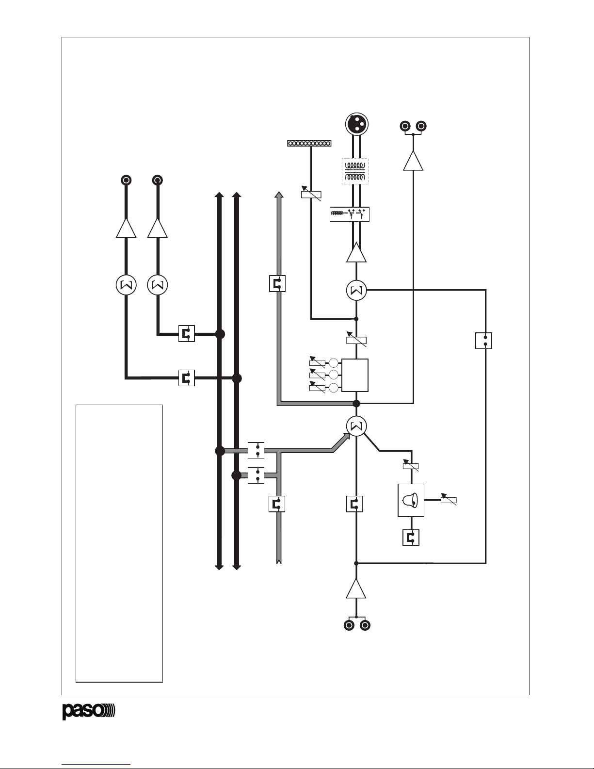
3.2 Assegnazione delle uscite L/R OUT
Gli stadi di miscelazione secondari (elementi Be
Cdello schema a blocchi di fig. 3.1.1) sono
assegnati di default ai bus dei segnali stereofonici
per mezzo dei due ponticelli inseriti nei connettori
CN105 (
linea destra
) e CN106 (
linea sinistra
).
Questi stadi effettuano, pertanto, la miscelazione
di tutti i segnali immessi su questi bus di
miscelazione. Il segnale ottenuto da questi stadi
sommatori è riportato alle prese di uscita L OUT
[6] (canale sinistro) e R OUT [7] (canale destro).
Rimuovendo i ponticelli dai connettori CN106 e
CN105 gli stadi di miscelazione [B] e [C] vengono
esclusi e le relative uscite [6] e [7] saranno,
pertanto, ammutolite.
NOTA (A): ad ogni linea di miscelazione deve
essere assegnato un solo stadio sommatore,
pertanto, se lo stadio sommatore principale [A],
dello stesso modulo d'uscita o di un'altro installato
nel sistema, viene assegnato ad una delle due
linee di miscelazione stereofoniche si dovrà
provvedere ad escludere lo stadio sommatore
secondario, [B] o [C], normalmente assegnato
a quella linea.
NOTA (B): se nel sistema sono installati più
moduli di uscita sarà necessario rimuovere i
ponticelli dei connettori CN105 e CN106 di tutti
i moduli d'uscita ad esclusione di quello dal quale
si desidera prelevare i segnali dei canali
stereofonici.
3.3 Interruzione del bus PA
Il segnale di uscita dello stadio di miscelazione
principale (elemento "A" dello schema a blocchi
di fig. 3.1.1) è inviato (selezione di default) al
piedino 10 (
uscita bus PA
) del connettore
multivia; tale segnale si presenterà quindi
all'ingresso, piedino 11 (
ingresso bus PA
) del
connettore multivia, dell'eventuale modulo posto
immediatamente a sinistra). Questo segnale può
essere utilizzato per poter disporre, ad esempio,
di più uscite (con relativi controlli di livello e tonalità)
appartenenti allo stesso segnale PA (vedi esempio
al par. 2.5.1). Se non si desidera inviare questo
segnale al modulo successivo (vedi esempio al
par. 2.5.2) è necessario rimuovere il ponticello
posto sul connettore CN104 o lasciare libero il
connettore immediatamente a sinistra di questo
modulo d'uscita.
3.2 Assigning the L and R OUT outputs
The secondary mixing stages (elements Band Cin
the block diagram shown in Figure 3.1.1) are
assigned by default to the busses of the stereo
signals by means of the two jumpers inserted into
connectors CN105 (
right line
) and CN106 (
left
line
). These stages will therefore take care of
the mixing of all the signals input onto these mixing
busses. The signal obtained from these summing
stages is sent to the L OUT [6] (left channel)
and R OUT [7] (right channel) output sockets. If
the jumpers are removed from connectors
CN106 and CN105, then mixing stages [B] and
[C] will be excluded and the associated outputs
[6] and [7] will therefore be muted.
NOTE (A): Only one summing stage has to be
assigned to each mixing line. Therefore, if the
main summing stage [A], of the same output
module or of another installed in the system, is
assigned to one of the two stereo mixing lines,
the secondary summing stage, [B] or [C],
normally assigned to that line, will have to be
excluded.
NOTE (B): If there are several output modules
installed in the system, the jumpers should be
removed from connectors CN105 and CN106
of all the output modules except for the one
from which the signals of the stereo channels
are to be taken.
3.3 Cutting off the PA bus
The output signal from the main mixing stage
(element "A" in the block diagram of Figure 3.1.1)
is sent (default selection) to pin 10 (
PA bus
output
) of the multi-way connector. This signal
will therefore be presented at the input on pin
11 (
PA bus input
) of the multi-way connector,
of the module - if any - positioned immediately
to the left. This signal can be used in order, for
example, to have several outputs at disposal
(with the relevant tone and level controls)
belonging to the same PA signal (see example
under point 2.5.1).
If this signal is not to be sent to the next module
(see example under point 2.5.2), then the jumper
positioned on connector CN104 should be
removed or the connector immediately to the
left of this output module should be left free.
- PMS2000 System -
Ref. 11/497-A PM2040-B
40
La regulación de nivel será efectuada por el
control del procesador externo y por el control
del módulo de entrada, teniendo en cuenta lo
siguiente:
- en el caso de generador de eco/
reverberación, o similares, la señal de salida
directa del módulo de entrada debe estar
configurada como post-fader y el control de
nivel del procesador externo deberá estar
regulado según la cantidad de efecto
deseado.
- en el caso de procesadores antilarsen,
procesadores de dinámica o similares, la señal
de salida directa del módulo de entrada deberá
estar configurada como pre-fader y el control
de nivel del módulo, correspondiente a esa
entrada, deberá estar a cero.
De niveauregeling zal worden uitgevoerd door
de regelaar van de externe processor en door
de regelaar van de ingangsmodule, met
inachtneming van het volgende:
- in het geval van een externe processor, moet
het directe uitgangssignaal van de
ingangsmodule worden ingesteld als post-
fader. De niveauregelaar van de externe
processor moet worden afgesteld op basis
van de hoeveelheid effect die men wil
bereiken.
- in het geval van anti- Larsen processors,
dynamiekprocessors en dergelijke, moet het
directe uitgangssignaal van de ingangsmodule
worden ingesteld als pre-fader en moet
de niveauregelaar van de module van deze
ingang op nul worden gezet.
Ejemplo B:
la señal audio aplicada en esta entrada
(procedente, por ejemplo, de una línea
telefónica) entra directamente en la etapa
sumadora [A] y puede ser empleada como
entrada prioritaria para señalizaciones de
emergencia. Cabe destacar de todas maneras
que las otras señales aplicadas en la etapa
sumadora no son enmudecidas por la señal
aplicada en esta entrada.
Ejemplo C:
empleando una matriz externa de conmutación
audio es posible utilizar esta entrada para
ajustar y balancear las líneas individuales de
salida de la matriz.
4.2 Salida balanceada
La salida BAL. OUT [10], de tipo balanceado y
provista de clavija XLR profesional con gancho
de retención, es considerada como la salida
principal de este módulo; en la fig. 4.2.1 se
indican sus polos.
Voorbeeld B:
het audiosignaal dat verbonden is met deze
ingang (en dat bijvoorbeeld afkomstig is van
een telefoonlijn) komt rechtstreeks in de som-
trap [A] binnen en kan gebruikt worden als
prioriteitsingang. Het is wel zo dat de andere
signalen die verbonden zijn met de som-trap
niet worden onderdrukt (muting) door het
signaal dat met deze ingang is verbonden.
Voorbeeld C:
bij gebruik van een externe audio schakelmatrix
kan deze ingang gebruikt worden voor het
afstellen en balanceren van de afzonderlijke
uitgangslijnen van de matrix.
4.2 Gebalanceerde uitgang
De gebalanceerde uitgang BAL. OUT [10] is
voorzien van een XLR- chassisdeel en is
bedoeld als hoofduitgang van deze module; op
afb. 4.2.1 ziet u de pinconfiguratie van deze
uitgang.
1: blindaje / pantalla
2: señal (lado caliente) / signaal (warme kant)
3: señal (lado frío) / signaal (koude kant)
Fig./Afb. 4.2.1

- PMS2000 System -
Ref. 11/497-A PM2040-B
10
3.4 Selezione del tipo di segnale di preavviso
Il generatore interno del segnale di preavviso
è impostato per generare un segnale di
tipo tri-tonale. Per impostare un segnale di tipo
bi-tonale è necessario rimuovere il ponticello
inserito nel connettore CN101.
3.5 Regolazione del segnale di preavviso
L'utente può regolare il livello e la tonalità del
segnale di preavviso agendo rispettivamente sui
trimmer P107 e P108.
NOTA
Se nel sistema sono installati più moduli di uscita
(vedi esempi al par. 2.5.1 e 2.5.2) sarà
necessario ridurre a zero il livello di uscita di tutti
i generatori di segnale di preavviso tranne di
quello da cui si desidera ottenere il segnale.
3.6 VU-METER
Il trimmer P106 permette di tarare l'indicatore
a barra di led [1]. L'indicatore visualizza il livello
del segnale di uscita alla presa BAL. OUT [10].
Questo indicatore è già tarato in fabbrica in modo
da accendere il led 0quando il livello di uscita
raggiunge il valore di 0.775 V RMS.
3.7 Trasformatore di linea
L'uscita principale BAL. OUT [9] è bilanciata
elettronicamente. É possibile dotare questa
uscita di un traslatore di linea inserendo la
scheda accessoria TM92 nel connettore CN102
dopo aver rimosso i due ponticelli presenti.
Il traslatore di linea permette di ottenere un
perfetto isolamento galvanico della linea di
uscita.
3.4 Selection of the type of warning signal
The internal warning-signal generator is set to
generate a three-tone signal.
To set a two-tone signal, it is necessary to
remove the jumper inserted in connector
CN101.
3.5 Adjustment of the warning signal
The user can adjust the level and the tone of
the warning signal by means of trimmers P107
and P108 respectively.
NOTE
If there is more than one output module installed
in the system (see examples under points 2.5.1
and 2.5.2), it will be necessary to lower the
output level of all the warning-signal generators
to zero with the exception of the one from which
the signal is to be obtained.
3.6 VU-METER
Trimmer P106 can be used to gauge the LED
bar indicator [1]. This indicator shows the level
of the output signal on the BAL. OUT socket
[10]. This indicator is already factory set so
that the "0" LED will light up when the output
level reaches a value of 0,775 V RMS.
3.7 Line transformer
The BAL. OUT main output [9] is electronically
balanced. It is possible to equip this output with
a line transformer by inserting the TM92
accessory card into connector CN102 after
removing the two jumpers that are present.
The line transformer makes it possible to achieve
perfect galvanic insulation of the output line.
- PMS2000 System -
Ref. 11/497-A PM2040-B
39
1
2
1: masa / massa
2: señal / signaal
Fig./Afb. 4.1
4. CONEXIONES
NOTA: todas las tomas phono ([6], [7], [8] y
[9]) están conectadas tal y como mostrado en
la fig. 4.1.
4. AANSLUITINGEN
OPMERKING: alle cinch- aansluitingen ([6], [7],
[8] en [9]) zijn aangesloten zoals is
weergegeven op afb. 4.1.
4.1 Entrada auxiliar
La señal de entrada se puede ajustar
(configuración de fábrica) con el control de
volumen y tonos. Si fuese necesario garantizar
que la señal sea de todas maneras difundida al
máximo nivel, independientemente de cualquier
ajuste manual (por ej. durante un anuncio de
emergencia), quitar el puente del conector
CN111 y ponerlo en el conector CN110.
4.1 Lijningang
Het ingangssignaal kan worden geregeld
(fabrieksinstelling) door de volume- en
toonregeling. Wanneer er gegarandeerd moet
worden dat het signaal in elk geval op het
maximumniveau wordt verspreid, ongeacht de
handmatige instellingen (bijvoorbeeld bij een
noodmelding), de brug van de connector CN111
halen en in de connector CN110 steken.
Esta entrada puede ser empleada como canal
de vuelta de efectos (ver el ejemplo Adescrito
a continuación), como entrada prioritaria (ver el
ejemplo B) o como entrada desde matriz (ver el
ejemplo C).
Deze ingang kan gebruikt worden als kanaal voor
het teruggeven van effecten (zie het voorbeeld
Adat verderop wordt beschreven), als
prioriteitsingang (zie voorbeeld B) of als ingang
vanaf de matrix (zie voorbeeld C).
BELANGRIJK!
De keuze van de ene modus sluit de andere
modus automatisch uit; dus als de brug in de
connector CN110 wordt gestoken moet de
connector CN111 noodzakelijkerwijs vrij zijn
en omgekeerd.
¡IMPORTANTE!
La selección de una modalidad excluye
automáticamente la otra; por lo tanto si se pone
el puente en el conector CN110, el conector
CN111 deberá necesariamente quedar libre y
viceversa.
Ejemplo A:
la señal microfónica preamplificada, sacada de
la salida directa de un módulo DOBLE ENTRADA
(PM2020-B), es enviada a un procesador
externo de señal (generador de eco/
reverberación, ecualizador paramétrico,
procesador anti-Larsen, u otro); la salida de
este procesador será aplicada en la entrada
auxiliar del módulo de salida.
Voorbeeld A:
het voorversterkte microfoonsignaal dat wordt
opgepakt van de directe uitgang van
een DUBBELE MICROFOONINGANGS-module
(PM2020-B), wordt naar een externe
signaalprocessor gestuurd (generator van
echo/ galm, parametrische equalizer, anti-
Larsen processor e.d.). De uitgang van deze
processor zal verbonden worden met de
lijningang van de uitgangsmodule.

- PMS2000 System -
Ref. 11/497-A PM2040-B
11
Fig. 4.1
4. CONNESSIONI
NOTA: tutte le prese phono ([6], [7], [8] e [9])
sono collegate come illustrato in fig. 4.1.
4. CONNECTIONS
NOTA: All the phono sockets ([6], [7], [8] and [9])
are connected as illustrated in Figure 4.1.
4.1 Ingresso ausiliario
Il segnale d'ingresso può essere regolato
(impostazione di fabbrica) dal controllo di volume
e toni. Qualora fosse necessario garantire che il
segnale venga comunque diffuso al massimo
livello, a prescindere da ogni regolazione manuale
(ad es. durante un annuncio d'emergenza),
estrarre il ponticello dal connettore CN111 ed
inserirlo nel connettore CN110.
4.1 Auxiliary input
The input signal can be adjusted (factory
setting) by means of the volume and tone
control. Should it be necessary to ensure that
the signal is in any case broadcast at the highest
possible volume regardless of any manual
adjustment (e.g. during an emergency
announcement), remove the jumper from
connector CN111 and fit it into connector
CN110.
Questo ingresso può essere utilizzato come
canale di ritorno effetti (vedi l'esempio Adi
seguito descritto), come ingresso prioritario
(vedi esempio B) o come ingresso da matrice
(vedi es. C).
IMPORTANTE!
La scelta di una modalità esclude l'altra; di
conseguenza se il ponticello viene inserito nel
connettore CN110, il connettore CN111 dovrà
necessariamente essere libero e viceversa.
Esempio A:
il segnale microfonico preamplificato, prelevato
dall'uscita diretta di un modulo DOPPIO
INGRESSO (PM2020-B), è inviato ad un
elaboratore esterno di segnale (generatore
di eco/riverbero, equalizzatore parametrico,
processore anti-Larsen, o altro); l'uscita di
questo elaboratore verrà applicata all'ingresso
ausiliario del modulo di uscita.
Example A:
The pre-amplified microphone signal, taken from
the direct output from a DOUBLE INPUT module
(PM2020-B), is sent to an external signal
processor (echo/reverberation generator,
parametric equaliser, anti-Larsen processor or
other). The output from this processor will be
applied to the auxiliary input of the output
module.
This input can be used as an effect return
channel (see example Adescribed below), as
a priority input (see example B) or as an input
from the matrix (see example C).
IMPORTANT NOTICE!
The choice of one mode automatically excludes
the other. This means that if the jumper is fitted
into connector CN110, connector CN111 will
necessarily be unjumpered and vice versa.
1
2
1: massa / gnd
2: segnale / signal
- PMS2000 System -
Ref. 11/497-A PM2040-B
38
3.4 Selección del tipo de señal de preaviso
El generador interno de la señal de preaviso
está configurado para generar una señal de tipo
con tres tonos. Para configurar una señal de
tipo bi-tonal es preciso quitar el puente aplicado
en el conector CN101.
3.5 Regulación de la del señal de preaviso
El usuario puede ajustar el nivel y el tono de
la señal de preaviso maniobrando, respecti-
vamente, los condensadores de ajuste P107
y P108.
NOTA
si en el sistema hay instalados varios módulos
de salida (ver los ejemplos en los párr. 2.5.1 y
2.5.2) será preciso reducir a cero el nivel de
salida de todos los generadores de señal de
preaviso salvo de aquél del cual se desea
conseguir la señal.
3.6 VU-METER
El condensador de ajuste P106 permite calibrar
el indicador de barras de LED [1]. El indicador
visualiza el nivel de la señal de salida en la toma
BAL. OUT [10]. Este indicador sale ya calibrado
de la fábrica a fin de encender el LED 0 cuando
el nivel de salida alcanza el valor de 0.775 V RMS.
3.7 Transformador de línea
La salida principal BAL. OUT [9] está balanceada
electrónicamente. Es posible equipar esta salida
con un trasladador de línea introduciendo la
tarjeta accesoria TM92 en el conector CN102
después de haber quitado los dos puentes
presentes. El trasladador de línea permite
conseguir un perfecto aislamiento galvánico de
la línea de salida.
3.4 Keuze van het attentiesignaal
De interne generator van het attentiesignaal
is ingesteld om een drietonig signaal te
genereren. Om een tweetonig signaal in te
stellen, dient u de jumper te verwijderen van
connector CN101.
3.5 Afstelling van het attentiesignaal
De gebruiker kan het volume en de toon van
het attentiesignaal afstellen met behulp van de
instelpotmeters P107 en P108.
OPMERKING
indien er meerdere uitgangsmodules in het
systeem zijn geïnstalleerd (zie de voorbeelden
uit par. 2.5.1 en 2.5.2), is het noodzakelijk het
uitgangsniveau van alle attentiesignaal modules
op nul te zetten, met uitzondering van het
uitgangsniveau van de module waarvan men
het signaal wil verkrijgen.
3.6 VU-METER
Met de instelpotmeter P106 kunt u de
ledindicatie [1] afstellen. De indicator geeft het
niveau van het uitgangssignaal bij de aansluiting
BAL. OUT [10] aan. Deze indicator is in de
fabriek reeds zodanig afgesteld dat hij de led 0
inschakelt wanneer het uitgangsniveau een
waarde bereikt van 0.775 V RMS.
3.7 Lijntransformator
De hoofduitgang BAL. OUT [9] is elektronisch
gebalanceerd. Het is mogelijk deze uitgang uit
te rusten met een lijntransformator door de
extra print TM92 in connector CN102 te steken
na de twee aanwezige jumpers te hebben
verwijderd. De lijntransformator zorgt ervoor
dat er een galvanische scheiding van de
uitgangslijn wordt verkregen.

- PMS2000 System -
Ref. 11/497-A PM2040-B
12
La regolazione di livello sarà effettuata dal
controllo del processore esterno e dal controllo
del modulo d'ingresso tenendo conto di quanto
segue:
- nel caso di generatore d'eco/riverbero, o simili,
il segnale di uscita diretta del modulo
d'ingresso dovrà essere impostato come
post-fader ed il controllo di livello del
processore esterno dovrà essere dosato in
base alla quantità di effetto desiderato.
- nel caso di elaboratori antilarsen, elaboratori
di dinamica o simili, il segnale di uscita diretta
del modulo d'ingresso dovrà essere impostato
come pre-fader ed il controllo di livello del
modulo, relativo a questo ingresso, dovrà
essere posto a zero.
Adjustment of the level will be carried out by
means of the controls of the external processor
or of the input module, taking the following into
account:
- In the case of an echo/reverberation generator
or similar equipment, the direct output signal
of the input module will have to be set as a
post-fader and control of the level of the
external processor will have to be adjusted on
the basis of the quantity of effect required.
- In the case of anti-Larsen processors,
dynamics processors or similar equipment, the
direct output signal of the input module will
have to be set as a pre-fader and control of
the level of the module, related to this input,
will have to be set at zero.
Esempio B:
il segnale audio applicato a questo ingresso
(proveniente, ad esempio, da una linea
telefonica) entra direttamente nello stadio
sommatore [A] può essere utilizzato come
ingresso prioritario per segnalazioni
d'emergenza. È da notare, comunque, che gli
altri segnali applicati allo stadio sommatore non
vengono ammutoliti dal segnale applicato a
questo ingresso.
Esempio C:
utilizzando una matrice di commutazione audio
esterna è possibile utilizzare questo ingresso per
regolare e bilanciare le singole linee di uscita
della matrice.
4.2 Uscita bilanciata
L'uscita BAL. OUT [10], di tipo bilanciato e
dotata di spina XLR professionale con gancio di
ritenuta, è intesa come uscita principale di
questo modulo; in fig. 4.2.1 ne è riportata la
piedinatura.
4.2 Balanced output
The BAL. OUT balanced output [10] equipped
with a professional XLR plug with a retaining
hook is understood to be the main output of
this module. Its pin-out is shown in Figure
4.2.1.
Example C:
By using an external audio switching matrix,
this input can be used to adjust and balance the
single matrix output lines.
Example B:
The audio signal applied to this input (coming,
for example, from a telephone line) enters the
summing stage [A] directly, and can be used
as a priority input for emergency signalling.
It should be noted, in any case, that the other
signals applied to the summing stage are not
muted by the signal applied to this input.
1: schermo / shield
2: segnale (lato caldo) / signal (warm side)
3: segnale (lato freddo) / signal (cold side)
Fig. 4.2.1
- PMS2000 System -
Ref. 11/497-A PM2040-B
37
3.2 Asignación de las salidas L/R OUT
Las etapas de mezcla secundaria (elementos B
y Cdel esquema de bloques de la fig. 3.1.1)
están asignadas, de manera predeterminada, a
los buses de las señales estereofónicas
mediante dos puentes colocados en los
conectores CN105 (línea derecha) y CN106
(línea izquierda). Estas etapas realizan por lo
tanto la mezcla de todas las señales introducidas
en estos buses de mezcla. La señal conseguida
por estas etapas sumadoras es enviada a las
tomas de salida L OUT [6] (canal izquierdo) y
R OUT [7] (canal derecho). Quitando los
puentes de los conectores CN106 y CN105,
las etapas de mezcla [B] y [C] quedan excluidas
y las correspondientes salidas [6] y [7] quedan
pues enmudecidas.
NOTA (A): a cada línea de mezcla se debe
asignar una sola etapa sumadora, por lo tanto,
si la etapa sumadora principal [A], del mismo
módulo de salida o de otro instalado en el
sistema, es asignada a una de las dos líneas de
mezcla estereofónicas, cabe proceder a excluir
la etapa sumadora secundaria, [B] o [C],
normalmente asignada a esa línea.
NOTA (B): si en el sistema hay instalados varios
módulos de salida será preciso remover los
puentes de los conectores CN105 y CN106 de
todos los módulos de salida salvo aquél del cual
se desea sacar las señales de los canales
estereofónicos.
3.3 Interrupción del bus PA
La señal de salida de la etapa de mezcla principal
(elemento Adel esquema de bloques de la
fig. 3.1.1) es enviada (selección predeterminada)
al polo 10 (salida bus PA) del conector multivía;
dicha señal se presentará pues en la entrada,
polo 11 (entrada bus PA) del conector multivía,
del eventual módulo situado inmediatamente a
la izquierda). Esta señal puede ser empleada
para poder disponer, por ejemplo, de varias
salidas (con correspondientes controles de nivel
y tono) pertenecientes a la misma señal PA (ver
el ejemplo en el párr. 2.5.1). Si no se desea
enviar esta señal al módulo sucesivo (ver el
ejemplo en el párr. 2.5.2) es preciso quitar el
puente colocado en el conector CN104 o dejar
libre el conector inmediatamente a la izquierda
de ese módulo de salida.
3.2 Toekenning van de uitgangen L/R OUT
De secundaire mengtrappen (elementen Ben C
van het blokschema van afb. 3.1.1) worden
standaard toegekend aan de bussen van de
stereo signalen. Dit gebeurt door middel van de
twee jumpers in de connectors CN105 (rechter
lijn) en CN106 (linker lijn). Deze trappen zijn dus
verantwoordelijk voor het mengen van alle
signalen die naar deze mengbussen worden
gestuurd. Het signaal dat door deze som-trappen
wordt verkregen, wordt doorgestuurd naar de
uitgangen L OUT [6] (linker kanaal) en R OUT
[7] (rechter kanaal). Door de jumpers van de
connectors CN106 en CN105 te verwijderen,
worden de mengtrappen [B] en [C] uitgesloten
en zullen de bijbehorende uitgangen [6] en [7]
dus worden onderdrukt (muting).
OPMERKING (A): aan iedere menglijn mag slechts
één som-trap worden toegekend; als de primaire
som-trap [A], van dezelfde uitgangsmodule of van
een andere in het systeem geïnstalleerde module
wordt toegekend aan één van de twee stereo
menglijnen, dient u ervoor te zorgen dat de
secundaire som-trap, [B] of [C], dat normaal aan
deze lijn is toegewezen, wordt uitgesloten.
OPMERKING (B): indien er meerdere
uitgangsmodules in het systeem zijn geïnstalleerd,
is het noodzakelijk de jumpers uit de connectors
CN105 en CN106 van alle uitgangsmodules te
verwijderen, met uitzondering van die van de
module waarvan u de signalen van de stereo
kanalen wilt oppakken.
3.3 Onderbreking van de PA-bus
Het uitgangssignaal van de primaire mengtrap
(element Avan het blokschema van afb. 3.1.1)
wordt volgens de standaardinstelling gestuurd
naar pin 10 (uitgang PA-bus) van de meerpolige
connector; dit signaal komt dus bij de ingang, pin
11 (ingang PA-bus) van de meerpolige connector,
die zich links van de module bevindt.
Dit signaal kan gebruikt worden om bijvoorbeeld
te kunnen beschikken over meer uitgangen (met
bijbehorende niveau- en toonregelaars) die
behoren tot hetzelfde PA-signaal (zie het
voorbeeld in par. 2.5.1). Indien u dit signaal
niet naar de volgende module wilt sturen (zie
het voorbeeld in par. 2.5.2), dient u de jumper
te verwijderen van de connector CN104 of de
connector die zich meteen links van deze
uitgangsmodule bevindt vrij te laten.

- PMS2000 System -
Ref. 11/497-A PM2040-B
13
Questa spina fornisce il segnale derivato dalla
miscelazione di tutti i segnali applicati allo stadio
sommatore principale (elemento Adello schema
a blocchi illustrato nella fig. 3.1.1).
Questo segnale, dopo essere stato equalizzato
dallo stadio controllo toni, può essere regolato
in ampiezza per mezzo del controllo di livello
MASTER [2].
Un relè (elemento Ddello schema a blocchi)
provvede a ritardare di qualche secondo
l'applicazione del segnale all'uscita quando il
sistema viene acceso.
Questa funzione, detta "
antibump
", serve a
prevenire il danneggiamento degli altoparlanti
causato dai forti transitori generati dai circuiti
elettronici all'accensione.
This plug supplies the signal originating from
the mixing of all the signals applied to the main
summing stage (element Aof the block diagram
in Figure 3.1.1).
After being equalised by the tone-control
stages, this signal can be amplitude-adjusted
by means of the MASTER level control [2].
A relay (element Din the block diagram) takes
care of delaying application of the signal to the
output for a few seconds when the system is
switched on.
This function, known as the "
anti-bump
"
function, has the purpose of preventing
damage to the loudspeakers caused by the
strong transients generated by the electronic
circuits on switching on.
4.3 Uscita per registratore
Alle due prese phono REC. OUT [8] è fornito
il segnale derivato dalla miscelazione di tutti i
segnali applicati allo stadio sommatore
principale. Questo segnale (monofonico) non
è influenzato dalla regolazione dei toni o del
livello e può essere applicato, ad esempio, ad
un'apparecchio di registrazione. Le due prese
phono sono collegate in parallelo tra loro per
facilitare il collegamento ad un apparecchio di
registrazione stereofonico.
4.4 Uscita stereofonica
Le due prese phono L OUT [6] ed R OUT [7]
forniscono il segnale derivato dalla miscelazione
di tutti i segnali applicati ai relativi stadi
sommatori (elementi Be Cdello schema a
blocchi di fig. 3.1.1). Questi segnali non sono
influenzati dalla regolazione dei toni e non sono
regolabili in ampiezza.
4.3 Recorder output
The signal originating from the mixing of all
the signals applied to the main summing stage
is supplied to the two REC. OUT phono sockets
[8]. This signal (mono) is not influenced by
the adjustment of the tones or of the level
and may be applied, for example, to a
recording device. The two phono sockets are
connected in parallel with one another so as
to make connection to a stereo recording
device easier.
4.4 Stereo output
The two L OUT [6] and R OUT [7] phono
sockets supply the signal originating from the
mixing of all the signals applied to their
respective summing stages (elements Band C
in the block diagram of Figure 3.1.1). These
signals are not influenced by adjustment of the
tones and their amplitude cannot be adjusted.
- PMS2000 System -
Ref. 11/497-A PM2040-B
36
Fig./Afb. 3.1.2
C
D
R103
R104
PR102
C144
R170
CN111
C114
R143
R158
CI103
R169
R176
R144
C116
R129
R131
R141
D117
C119
R146
R130
R132
D118
D119
PR101PR104
RL101
C143
R172
R173
R171
R174
TR106
X109
L101
X117
X104
R142
C142
CI102
X112
X121
C140
TR107
R128
X131
X123
X133
C108
R133
R134
R148
C120
C121
C129
C117
C118
CN102
D116
CI108
EF
R164
R166
C136
R167
D126
D123
D124
X134
X132
PR103
X113
C146
R177
R178
R179
TR108
C149
C112
C123
R101
R102
R138
R127
R136
R137
P109
R147
P107
TR103
TR104
CN101
CN103
CI106
CI107
X118
X128
R160
C139
R168
C137
X138
C133
D111
R152
D114
R114
X143
X144
X142
C128
R149
R150C113
P108
X111
C131
X126
X127
X129
R163
D121
D122
C134
CN108
X105
R151 R153
T0NE3
R118
R121
D110
R113
TR101
CI110
CF102
C148
C147
CF101
R120
R122
R123
CI109
X110
X124
X140
X146
X136
R119
R159
C102
C109
R117
P104
R124
R116
C130
P103
R110
TR102
CF103
R161
X115
X114
C101
C126
R112
D112
D113
C110
R109
R140
R157
C106
CI101
CI104
X101
X102
X103
X106
C141
C138
X139
CN105 CN106
C132
L
R
R154
CN104
CN104
X108
R162
CN107
CN109
X141
R
L
M
O
R156
C124
R106
R107
R108
P101
P102
C103
C103
C104
C107
C107
R111
X130
B
A
H
I
CN111
CN110
CN102
P106
P109
P107 P108
CN105
CN106
CN101 CN109
CN108
CN107
CN104
CN103

- PMS2000 System -
Ref. 11/497-A PM2040-B
14
5. REGOLAZIONI ED USO
5.1 Controllo di volume
Con il controllo MASTER [2] è possibile regolare
il livello del segnale di uscita della sola presa
BAL. OUT [10].
L'ampiezza di questo segnale è visualizzata
dall'indicatore di livello [1], l'indicazione 0indica
un livello di uscita di 0 dBV (0.775 volt).
6. ACCESSORI
Trasformatore di uscita ....................... TM92
5.3 Generatore di segnale di preavviso
Questo modulo incorpora un generatore di
segnale di preavviso a due o tre toni.
Il segnale viene generato ed immesso nel solo
stadio sommatore principale (elemento [A] dello
schema a blocchi di fig. 3.1.1), ogni qualvolta
venga rilevato un impulso di abilitazione sulla
linea CHIME del bus di comunicazione.
NOTA
La linea
chime
è comune a tutti i moduli del
sistema, pertanto, tutti i generatori installati nel
sistema vengono attivati in presenza dell'impulso
di abilitazione (vedere, a riguardo, il par. 3.5).
5.2 Controlli di tonalità
Questo modulo dispone di un accurato controllo
di tonalità a tre bande. Il campo d'intervento è
ottimizzato per ognuno dei tre controlli in modo
tale da garantire un'armoniosa ed efficace
equalizzazione del suono. Per esaltare o
attenuare la gamma di frequenze più vicina a
quella vocale si può intervenire agendo sul
controllo dei toni medi [4]; per esaltare o
attenuare gli estremi della banda audio devono
essere utilizzati i controlli dei toni bassi [5] e
dei toni acuti [3].
NOTA
un'intervento eccessivo dei controlli di tonalità
raramente porta ad un risultato accettabile,
per risolvere problemi di difficile sonorizzazione
(ambienti, ad esempio, con determinate
frequenze disturbanti o attenuate) è
consigliabile l'utilizzo di un equalizzatore esterno
dotato di un maggior numero di controlli.
5. ADJUSTMENTS AND USE
5.1 Volume control
Using the MASTER control [2], it is possible to
adjust the level of the output signal of the
BAL. OUT socket only [10].
The amplitude of this signal is shown by the
level indicator [1]. When it shows 0this
indicates an output level of 0 dBV (0.775 Volts).
5.2 Tone controls
This module has an accurate three-band tone
control. The range of intervention is optimised
for each of the three controls in such a way as
to guarantee smooth and effective equalisation
of the sound. To exalt or attenuate the
frequency range closest to voice frequency it
is possible to intervene on the medium-tone
control [4]; to exalt or attenuate the extreme
ends of the audio band, the bass tone control
[5] and the treble tone control [3] have to be
used.
NOTE
Excessive application of the tone control hardly
ever leads to an acceptable result. To solve
problems concerning difficulties in distributing
the sound (for example, in environments where
there are certain disturbing or attenuating
frequencies), it is advisable to use an external
equaliser equipped with a larger number of
controls.
5.3 Warning signal generator
This module incorporates a two or three-tone
warning signal generator.
This signal is generated and input only into the
main summing stage (element [A] of the block
diagram of Figure 3.1.1), each time an enabling
pulse is detected on the CHIME line of the
communications bus.
NOTE
The
chime
line is common to all the modules of
the system. All the generators installed in the
system are therefore activated in the presence
of the enabling pulse (in this respect, see point
3.5).
6. ACCESSORIES
Output transformer ............................ TM92
- PMS2000 System -
Ref. 11/497-A PM2040-B
35
Fig./Afb. 3.1.1
RECORD
OUT
BAL.
OUT
PA
BUS
OUTPUT
PA
BUS
INPUT
LEFT
OUTPUT
LEFT
MIX BUS
LEFT
MIX BUS
RIGHT
OUTPUT
RIGHT
MIX BUS
RIGHT
MIX BUS
MASTER
CONTROL
TONE
CONTROL
AUX
IN
CN108
CN107
CN101
P108
P107
OUTPUT
LEVEL
METER
+
-
CN109
CN104
CN102
TM92
[]9
[]8
[]1
[]2
[]10
[]7
CN106 CN105
B
EE
E
E
D
F
A
E
C
[]6
345
Z
CN110
EXT.DIR
CN111
EXT.REG
[A] Etapa sumadora principal / Primaire som-trap
[B] Etapa sumadora secundaria / Secundaire som-trap
[C] Etapa sumadora secundaria / Secundaire som-trap
[D] Relé salida retrasada / Relais vertraagde uitgang
[E] Etapa amplificador / Versterkingstrap
[F] Circuito din-don / Ding-dong circuit

- PMS2000 System -
Ref. 11/497-A PM2040-B
15
7. CARATTERISTICHE TECNICHE 7. TECHNICAL SPECIFICATIONS
- PMS2000 System -
Ref. 11/497-A PM2040-B
34
3. CONFIGURACIÓN DE FUNCIONAMIENTO
Este módulo dispone de un cierto número de
controles mediante los cuales es posible
configurar todas sus funciones operativas.
Antes de instalar el módulo en el contenedor es
oportuno verificar si las configuraciones
predeterminadas, efectuadas por el fabricante,
satisfacen las necesidades del sistema en el cual
el módulo deberá trabajar y eventualmente
proceder a efectuar las modificaciones
necesarias. En la fig. 3.1.2 (pág. 36) se destaca
la disposición de los distintos conectores y
controles presentes en el circuito impreso del
módulo. En la pág. 46 se presenta una tabla
recopiladora de todas las configuraciones del
módulo.
3.1 Asignación de la salida BAL. OUT
La etapa de mezcla principal (elemento Adel
esquema de bloques), cuya señal de salida es
enviada a la toma BAL. OUT [10] (salida
balanceada en XLR), puede ser asignada a una
de las tres líneas de señal: bus PA (mono), bus
IZQUIERDO y bus DERECHO. La asignación es
efectuada mediante un puente cortocircuitador
situado en los terminales de uno de los
conectores CN107, CN108 o CN109.
La configuración predeterminada asigna la
salida principal al bus PA (el puente
cortocircuitador está colocado en los terminales
del conector CN107). Para asignar esta salida
al bus izquierdo será preciso remover el puente
del conector CN107 y ponerlo en el conector
CN108; para asignar esta salida al bus derecho
será preciso poner el puente en el conector
CN109.
NOTA (A)
la etapa sumadora puede ser asignada a una
sola de las tres líneas de mezcla así como es
preciso asignar a cada línea una sola etapa
sumadora.
NOTA (B)
si la etapa sumadora principal [A] es asignada a
una de las dos líneas de mezcla estéreo,
todas las restantes etapas sumadoras
correspondientes a esa línea, presentes en el
sistema, deben quedar excluidas (ver párr. 3.2).
3. GEBRUIKSINSTELLINGEN
Deze module beschikt over een bepaald aantal
regelaars waarmee alle gebruiksfuncties van
de module kunnen worden ingesteld.
Alvorens de module in het rack te installeren is
het goed om te controleren of de
standaardinstellingen , die zijn uitgevoerd door
de fabrikant, geschikt zijn voor het systeem
waarbinnen de module zal werken. Voer
eventueel de nodige wijzigingen door.
Op afb. 3.1.2 (pag. 36) ziet u de positie van
de verschillende connectors en regelaars op
de print van de module.
Op pag. 46 vindt u een overzichtstabel met
alle instellingen van de module.
3.1 Toekenning van de uitgang BAL. OUT
De belangrijkste mengtrap (element Avan het
blokschema), waarvan het uitgangssignaal naar
de aansluiting BAL. OUT [10] (gebalanceerde
uitgang op XLR) wordt gestuurd, kan worden
toegekend aan één van de drie signaallijnen:
PA-bus (mono), LINKER bus en RECHTER bus.
De toekenning wordt uitgevoerd door middel
van een jumper op één van de connectors
CN107, CN108 of CN109.
De standaardinstelling kent de hoofduitgang toe
aan de PA-bus (de jumper wordt aangebracht
op de connector CN107). Om deze uitgang toe
te kennen aan de linker bus dient u de jumper te
verwijderen van de connector CN107 en deze
te installeren in de connector CN108. Om deze
uitgang toe te kennen aan de rechter bus, dient
u de jumper te installeren in de connector
CN109.
OPMERKING (A)
De som-trap kan aan slechts één van de drie
menglijnen worden toegekend, net zoals aan
elke afzonderlijke lijn slechts één som-trap moet
worden toegekend.
OPMERKING (B)
Als de primaire som-trap [A] wordt toegekend
aan één van de twee stereo menglijnen, moeten
alle overige som-trappen van die lijn die in het
systeem aanwezig zijn worden uitgesloten
(zie par. 3.2).
Uscita “PA” “PA” output
Tipo Bilanciata elettronicamente Type
Electronically balanced
Livello / impedenza 775 mV / 600 ΩLevel / impedance
Risposta in frequenza 40 ÷ 20.000 Hz (0 ÷ -1 dB) Frequency response
25 ÷ 100.000 Hz (0 ÷ -3 dB)
Distorsione < 0,1% Distortion
Uscita “STEREO” “STEREO” output
Tipo Sbilanciata Type
Unbalanced
Livello / impedenza 770 mV / 1 kΩLevel / impedance
Risposta in frequenza 40 ÷ 20.000 Hz (0 ÷ -1 dB) Frequency response
25 ÷ 100.000 Hz (0 ÷ -3 dB)
Distorsione < 0,1% Distortion
Uscita “TAPE” “TAPE” output
Tipo Sbilanciata Type
Unbalanced
Livello / impedenza 450 mV / 1 kΩLevel / impedance
Risposta in frequenza 40 ÷ 20.000 Hz (0 ÷ -1 dB) Frequency response
25 ÷ 100.000 Hz (0 ÷ -3 dB)
Distorsione < 0,1% Distortion
Entrata ausiliaria Auxiliary input
Sensibilità / impedenza 290 mV / 50 kΩSensitivity / impedance
Rapporto segnale/disturbo > 91 dB S/N ratio
Rapporto segnale/disturbo (“A”) > 94 dbA S/N ratio (“A”)
Generali Overall
Correzione toni bassi ± 10 dB (@ 100 Hz) Bass tone correction
Correzione toni medi ± 6 dB (@ 1 kHz) Middle tone correction
Correzione toni acuti ± 10 dB (@ 10 kHz) Treble tone correction
Ritardo inserzione 2 sec. Insertion delay
Larghezza modulo 38 mm Module width
24 V / 17 mA
Consumo +15 V / 22 mA Consumption
-15 V / 18 mA
11-497_A_prova.pmd 10/02/2005, 10.5715

- PMS2000 System -
Ref. 11/497-A PM2040-B
16
1. DESCRIPTION GENERALE 1. ALLGEMEINE BESCHREIBUNG
1.1 Description du panneau frontal
[1] Indicateur du niveau de sortie.
[2] Contrôle du volume de sortie.
[3] Contrôle aiguës.
[4] Contrôle moyens.
[5] Contrôle graves.
1.2 Description du panneau postérieur
[6] Prise sortie canal gauche.
[7] Prise sortie canal droit.
[8] Prises sortie pour enregistreur.
[9] Prises entrée auxiliaire.
[10] Fiche sortie équilibrée.
1.1 Beschreibung Frontpaneel
[1] Anzeige Ausgangsstufe.
[2] Regler der Ausgangslautstärke.
[3] Hochtonregler.
[4]Regler der mittleren Töne.
[5] Tieftonregler.
1.2 Beschreibung Rückpaneel
[6] Ausgangsbuchse linker Kanal.
[7] Ausgangsbuchse rechter Kanal.
[8] Ausgangsbuchse Kassettengerät.
[9] Buchse f. Hilfseingänge.
[10] Stecker für den symmetrierten Ausgang.
- PMS2000 System -
Ref. 11/497-A PM2040-B
33
Fig./Afb. 2.5.2
(*)
El puente colocado en el conector CN104 de este
módulo de salida (ver párr. 3.3) es preciso quitarlo.
De esta manera es posible separar los dos sistemas
interrumpiendo, en este punto, la línea de mezcla PA.
(*)
de jumper die is aangebracht op de connector CN104
van deze uitgangsmodule (zie par. 3.3) moet worden
verwijderd. Op deze manier is het mogelijk de twee
systemen te scheiden door op dit punt de menglijn PA te
onderbreken.
Difusores
Luidsprecker
Amplificador [B]
Versterker [B] Amplificador [A]
Versterker [A]
Columnas sonoras
Audiozuilen
Sistema
Systeem
[B]
Sistema
Systeem
[A]

- PMS2000 System -
Ref. 11/497-A PM2040-B
17
2. GÉNÉRALITÉS
Le module de sortie est nécessaire pour le
mixage des tous les signaux transmis sur les
bus des différents modules. Il dispose d'une
sortie principale mono, d'une sortie stéréo,
d'une sortie pour magnétophone et d'une
entrée auxiliaire. La fig. 3.1.1 montre le
schéma par blocs du module. Les modalités de
fonctionnement de ce module peuvent être
configurées par l'utilisateur.
Pour garantir une bonne configuration de
fonctionnement, il est important de lire
attentivement les indications relatives aux
fonctions des lignes (bus) assurant la
connexion des différents modules et de
consulter les schémas d'application présents
dans le manuel des instructions du support
des modules mod. PMS2002-B.
Ci-après sont fournies un certain nombre
d'indications générales qui permettent
d'interpréter correctement les indications
fournies dans les différentes chapitres.
2.1 Ligne de mixage mono
Également désignée comme BUS PA, il s'agit de
la ligne de mixage principale sur laquelle tous les
signaux du canal mono sont mixés.
2.2 Ligne de mixage canal gauche
Elle fait partie, tout comme le canal droit, des
lignes de mixage des signaux stéréo
généralement utilisées pour les sources
musicales. C'est la ligne sur laquelle sont mixés
tous les signaux relatifs au canal gauche de tous
les supports raccordés.
2.3 Ligne de mixage canal droit
Elle fait partie, tout comme le canal gauche, des
lignes de mixage des signaux stéréo. C'est la
ligne sur laquelle sont mixés tous les signaux
relatifs au canal droit de tous les supports
raccordés.
2.4 Ligne CHIME
Il s'agit de la ligne d'activation du signal
d'annonce, commune à tous les modules (y
compris ceux des éventuels supports
d'extension).
2. ALLGEMEINES
Das Ausgangsmodul ist erforderlich, um alle
Signale, die von verschiedenen Modulen an die
Busse gegeben werden, zu mischen. Es sind
vorhanden: ein Mono-Hauptausgang, ein
Stereo-Ausgang, ein Ausgang für das
Kassettengerät und ein Hilfseingang. In Abb.
3.1.1 ist das Blockschema des Moduls
dargestellt. Die Funktionsmodalitäten dieses
Moduls sind weitgehend vom Anwender
konfigurierbar.
Zum Zweck einer ordnungsgemäßen Einstellung
des Betriebs müssen die Anweisungen zur
Funktionalität der Leitungen (Busse), die
verschiedenen Module miteinander verbinden,
sowie die Anwendungsschemata des
Bedienungshandbuches des Aufnahmekorbs
PMS2002-B der Module aufmerksam gelesen
werden. Nachfolgend sind einige generelle
Erwägungen zu Zweck eines korrekten
Verständnisses der in den nächsten Abschnitten
angegebenen Anweisungen aufgeführt.
2.1 Mono-Mischleitung
Bezeichnet auch als BUS PA - dies ist die
Hauptmischleitung: auf dieser Leitung werden
alle Signale des Mono-Kanals gemischt.
2.2 Mischleitung linker Kanal
Diese Leitung ist, zusammen mit dem analogen
rechten Kanal, Bestandteil der Mischleitungen
der Stereosignale, die normalerweise für
Musikquellen eingesetzt werden. An dieser
Leitung werden alle Signale des linken Kanals
aller angeschlossenen Körbe gemischt.
2.3 Mischleitung rechter Kanal
Diese Leitung ist Bestandteil, zusammen mit dem
analogen linken Kanal, der Mischleitungen
der Stereosignale. An dieser Leitung werden
alle Signale des rechten Kanals aller
angeschlossenen Körbe gemischt.
2.4 CHIME-Leitung
Dies ist die Freigabeleitung für das
Ankündigungssignal, die von allen Modulen
gemeinsam verwendet wird (einschließlich der in
eventuell vorhandenen Erweiterungskörben).
- PMS2000 System -
Ref. 11/497-A PM2040-B
32
Fig./Afb. 2.5.1
Difusores a bocina
Hoorns
Difusores
Luidsprecker
Columnas sonoras
Audiozuilen
2.5 Instalación de varios módulos de
salida en un mismo sistema
Para realizar determinadas configuraciones es
posible instalar, en un mismo sistema, varios
módulos de salida. En general es posible
distinguir, relativamente al empleo de los
módulos de salida, dos configuraciones
principales:
2.5.1 compartimiento total de los buses
de mezcla
Para disponer de varias salidas con la
misma señal pero con regulaciones
distintas (ver el ejemplo mostrado en la
fig. 2.5.1).
2.5.2 compartimiento parcial de los
buses de mezcla
Para realizar, en un mismo contenedor,
varios sistemas de amplificación semi-
independientes (ver el ejemplo
mostrado en la fig. 2.5.2).
2.5 Installatie van meerdere uitgang-
modules in hetzelfde systeem
Om bepaalde configuraties tot stand te
brengen, is het mogelijk om meerdere
uitgangsmodules in hetzelfde systeem te
installeren. Met betrekking tot het gebruik van
de uitgangsmodules kunnen in grote lijnen twee
hoofdconfiguraties onderscheiden worden:
2.5.1 de mengbussen worden volledig
gedeeld
om te kunnen beschikken over meerdere
uitgangen met hetzelfde signaal maar
met verschillende afstellingen (zie het
voorbeeld uit afb. 2.5.1).
2.5.2 de mengbussen worden
gedeeltelijk gedeeld
om binnen hetzelfde module-rack
meerdere semi-onafhankelijke versterking-
systemen te realiseren (zie het voorbeeld
uit afb. 2.5.2).

- PMS2000 System -
Ref. 11/497-A PM2040-B
18
2.5 Installation de plusieurs modules de
sortie sur un même système
Pour réaliser certaines configurations, il est
possible d'installer sur un même système plusieurs
modules de sortie. On distingue généralement,
pour ce qui concerne l'utilisation des modules de
sortie, deux configurations principales:
2.5.1 Regroupement total
des bus de mixage
pour disposer de plusieurs sorties avec
le même signal mais avec des réglages
différents (voir l'exemple de la fig. 2.5.1).
2.5.2 Regroupement partiel
des bus de mixage
pour réaliser sur un même support
plusieurs systèmes d'amplification semi-
indépendants (voir l'exemple de la fig.
2.5.2).
2.5 Installation von mehreren
Ausgangsmodulen im gleichen System
Zur Herstellung bestimmter Konfigurationen
können in einem System mehrere Ausgangsmodule
installiert werden. Im Hinblick auf die Verwendung
der Ausgangsmodule können im wesentlichen zwei
Hauptkonfigurationen unterschieden werden:
2.5.1 Vollständiges Sharing
der Mischbusse
Zum Zweck der Verfügbarkeit von
mehreren Ausgänge mit dem gleichen
Signal aber unterschiedlichen Einstellungen
(s. Beispiel in Abb. 2.5.1).
2.5.2 Partielles Sharing
der Mischbusse
Für die Installation von mehreren halb-
unabhängigen Verstärkersystemen in
einem Korb (s. Beispiel in Abb. 2.5.2).
Fig./Abb. 2.5.1
Pavillons
Trichterlautspreher
Diffuseurs
Lautsprecher
Colonnes sonores
Tönsaule
- PMS2000 System -
Ref. 11/497-A PM2040-B
31
2. CONSIDERACIONES GENERALES
El módulo de salida es necesario para efectuar
la mezcla de todas las señales introducidas en
los buses por los distintos módulos.
Hay disponibles una salida principal monofónica,
una salida estereofónica, una salida para
grabadora y una entrada auxiliar. En la fig. 3.1.1
se indica el esquema de bloques del módulo.
Las modalidades de funcionamiento de este
módulo son ampliamente configurables por el
usuario. Para una configuración correcta del
funcionamiento es oportuno leer detenidamente
las indicaciones acerca de la funcionalidad de
las distintas líneas (buses) que enlazan entre
ellos los distintos módulos y los esquemas
aplicativos presentados en el manual de
instrucciones del contenedor de módulos mod.
PMS2002-B. A continuación se presentan unas
consideraciones generales de utilidad para
entender correctamente las indicaciones
presentadas en los párrafos siguientes.
2.1 Línea de mezcla mono
También conocida como BUS PA - es la línea de
mezcla principal: en esta línea son mezcladas
todas las señales correspondientes al canal
monofónico.
2.2 Línea de mezcla canal izquierdo
Forma parte, junto con el análogo canal derecho,
de las líneas di mezcla de las señales
estereofónicas utilizadas, en general, para
fuentes musicales. En esta línea son mezcladas
todas las señales correspondientes al canal
izquierdo de todos los contenedores conectados.
2.3 Línea de mezcla canal derecho
Forma parte, junto con el análogo canal izquierdo,
de la línea de mezcla de las señales
estereofónicas. En esta línea son mezcladas
todas las señales correspondientes al canal
derecho de todos los contenedores conectados.
2.4 Línea CHIME
Es la línea de habilitación de la señal de preaviso,
común para todos los módulos (incluidos
aquellos de los eventuales contenedores de
expansión).
2. ALGEMENE OPMERKINGEN
De uitgangsmodule is nodig voor het mengen
van alle signalen die door de verschillende
modules naar de bussen worden gestuurd.
Beschikbaar zijn een mono hoofduitgang, een
stereo-uitgang, een uitgang voor opname en
een lijningang. Op afb. 3.1.1 ziet u het
blokschema van de module.
De gebruiksmodes van deze module kunnen door
de gebruiker op vele verschillende manieren
worden geconfigureerd.
Om de module correct in te stellen dient u de
aanwijzingen met betrekking tot de functies van
de lijnen (bussen) die de verschillende modules
met elkaar verbinden en de toepassingsschema's
uit de instructiehandleiding van de modules van
het model PMS2002-B aandachtig te
bestuderen. In de volgende paragrafen vindt u
enige algemene beschouwingen die nuttig zijn
om de in de verdere paragrafen gegeven
aanwijzingen correct te interpreteren.
2.1 Mono menglijn
Ook wel PA-BUS genoemd - dit is de
hoofdmenglijn: op deze lijn worden alle signalen
van het monokanaal gemengd.
2.2 Menglijn linkerkanaal
Maakt, samen met het analoge rechterkanaal,
deel uit van de menglijnen van de stereosignalen,
in het algemeen voor muziekbronnen gebruikt.
Op deze lijn worden alle signalen van het
linkerkanaal van alle aangesloten module-racks
gemengd.
2.3 Menglijn rechterkanaal
Maakt, samen met het analoge linkerkanaal, deel
uit van de menglijn van de stereo signalen.
Op deze lijn worden alle signalen van het
rechterkanaal van alle aangesloten module-racks
gemengd.
2.4 CHIME-lijn
Deze lijn dient voor de activering van het
attentiesignaal, gemeenschappelijk voor alle
modules (met inbegrip van die van de eventuele
uitbreidingsmodules).

- PMS2000 System -
Ref. 11/497-A PM2040-B
19
Fig./Abb. 2.5.2
(*)
Le cavalier présent sur le connecteur CN104 de ce
module de sortie (voir chap. 3.3) doit être retiré.
Ceci permet de séparer les deux systèmes en intercalant,
à ce niveau, la ligne de mixage PA.
(*)
Die Brücke auf dem Anschlußstück CN104 dieses
Ausgangsmoduls (s. Abschnitt 3.3) muß entfernt
werden. Auf diese Weise besteht die Möglichkeit, die
beiden Systeme durch die Unterbrechung der
Mischleitung PA an diesem Punkt zu trennen.
Diffuseurs
Lautsprecher
Amplificateur [B]
Verstärker [B] Amplificateur [A]
Verstärker [A]
Colonnes sonores
Tonsäule
Système
System
[B]
Système
System
[A]
- PMS2000 System -
Ref. 11/497-A PM2040-B
30
1. DESCRIPCIÓN GENERAL 1. ALGEMENE BESCHRIJVING
1.1 Descripción del panel frontal
[1] Indicador del nivel de salida.
[2] Control del volumen de salida.
[3] Control tonos agudos.
[4] Control tonos medios.
[5] Control tonos bajos.
1.2 Descripción del panel trasero
[6] Toma salida canal izquierdo.
[7] Toma salida canal derecho.
[8] Tomas salida para grabadora.
[9] Tomas entrada auxiliar.
[10] Clavija salida balanceada.
1.2 Beschrijving achterpaneel
[6] Uitgang linkerkanaal.
[7] Uitgang rechterkanaal.
[8] Uitgangen voor opname.
[9] Chassisdelen lijningang.
[10] Gebalanceerde uitgang.
1.1 Beschrijving frontpaneel
[1] Indicator uitgangsniveau.
[2] Regeling uitgangsvolume.
[3] Regeling hoge tonen.
[4] Regeling middentonen.
[5] Regeling lage tonen.

- PMS2000 System -
Ref. 11/497-A PM2040-B
20
3. CONFIGURATION DE FONCTIONNEMENT
Ce module dispose d'un certain nombre de
contrôles par l'intermédiaire desquels il est
possible de configurer toutes les fonctions.
Avant d'installer le module, il convient de
s'assurer que les configurations standard, celles
programmées par défaut par le constructeur,
sont adaptées aux nécessités du système sur
lequel le module doit être utilisé, et au besoin,
d'apporter les modifications nécessaires.
La fig. 3.1.2 (page 22) montre la disposition des
différents connecteurs et des contrôles présents
sur le circuit imprimé du module.
Le tableau de la page 45 fournit un récapitulatif
de toutes les configurations du module.
3.1 Attribution de la sortie BAL. OUT
L'étage de mixage principal (élément Adu
schéma par blocs), dont le signal de sortie est
transmis à la prise BAL. OUT [10] (sortie
équilibrée sur XLR), peut être attribué à une
des trois lignes de signal: bus PA (mono), bus
GAUCHE et bus DROIT. L'attribution s'effectue
au moyen d'un cavalier de court-circuit installé
sur les terminaisons d'un des connecteurs
CN107, CN108 ou CN109.
La configuration standard attribue la sortie
principale au bus PA (le cavalier de court-circuit
est placé sur les terminaisons du connecteur
CN107). Pour attribuer cette sortie au bus
gauche, il est nécessaire de retirer le cavalier
du connecteur CN107 et de l'installer sur le
connecteur CN108; pour attribuer cette sortie
au bus droit, il est nécessaire d'installer le
cavalier sur le connecteur CN109.
NOTE (A)
L'étage additionneur peut être attribué à une
seule des trois lignes de mixage, de même qu'un
seul étage additionneur doit être attribué à
chaque ligne.
NOTE (B)
Si l'étage additionneur principal [A] est attribué
à une des deux lignes de mixage stéréo, tous
les autres étages additionneurs présents sur le
système correspondant à cette ligne devront
être exclus (voir chap. 3.2).
3. BETRIEBSEINSTELLUNGEN
Dieses Modul verfügt über eine gewisse Anzahl
an Reglern, mit deren Hilfe alle operativen
Funktionen des Moduls eingestellt werden
können. Vor der Installation des Moduls im Korb
sollte überprüft werden, ob die werksseitig
erfolgten Default-Einstellungen den
Anforderungen des Systems, in dem das Modul
betrieben wird, genügen und eventuell die
erforderlichen Änderungen durchgeführt
werden. In Abb. 3.1.2 (Seite 22) ist die Lage
der Anschlußstücke und Positionskontrollen auf
der Platine des Moduls dargestellt.
Auf Seite 45 ist eine Übersichtstabelle mit allen
Moduleinstellungen vorhanden.
3.1 Zuweisung des Ausgangs BAL. OUT
Das Hauptmischstadium (Element Ades
Blockschemas), dessen Ausgangssignal an die
Buchse BAL. OUT gesendet wird [10]
(symmetrierter Ausgang auf XLR), kann einer der
drei Signalleitungen zugewiesen werden: Bus PA
(Mono), Bus LINKS und Bus RECHTS. Die Zuweisung
erfolgt mit Hilfe einer Kurzschlußüberbrückung
auf den Endstücken auf einem der Anschlußstücke
CN107, CN108 oder CN109.
Die Default-Einstellung weist den Hauptausgang
dem Bus PA zu (die Kurzschlußüberbrückung sitzt
auf den Endstücken des Anschlusses CN107).
Zum Zweck der Zuweisung dieses Ausgangs an
den linken Bus muß die Kurzschlußüberbrückung
vom Anschlußstück CN107 entfernt und an das
Anschlußstück CN108 gesetzt werden; zur
Zuweisung dieses Ausgangs an den rechten Bus
muß die Kurzschlußüberbrückung an den Anschluß
CN109 gesetzt werden.
ANMERKUNG (A)
Das Summenstadium kann auch nur einer der
drei Mischleitungen zugewiesen werden; einer
Mischleitung kann nur ein Summenstadium
zugewiesen werden.
ANMERKUNG (B)
Falls das Hauptsummenstadium [A] einer der
beiden Stereo-Mischleitungen zugewiesen wird,
müssen alle übrigen, im System vorhandenen
Summenstadien dieser Leitung ausgeschlossen
werden (s. Abschnitt 3.2).
- PMS2000 System -
Ref. 11/497-A PM2040-B
29
SORTIE "PA" "PA" AUSGANG
Type Équilibrée électroniquement
Elektronisch symmetriert Typ
Niveau / Impédance 775 mV / 600 ΩStufe / Impedanz
Réponse en fréquence 40 ÷ 20000 Hz (0÷ -1 dB)
25 ÷ 100000 Hz (0÷-3 dB) Frequenzgang
Distorsion < 0,1 % Klirrgrad
SORTIE "STEREO" "STEREO" AUSGANG
Type non equilibrée/Unabgeglichener Typ
Niveau / Impédance 770 mV / 1 kΩStufe / Impedanz
Réponse en fréquence 40 ÷ 20000 Hz (0÷ -1 dB)
25 ÷ 100000 Hz (0÷-3 dB) Frequenzgang
Distorsion < 0,1 % Klirrgrad
SORTIE "TAPE" "TAPE" AUSGANG
Type non equilibrée/Unabgeglichener Typ
Niveau / Impédance 450 mV / 1 kΩStufe / Impedanz
Réponse en fréquence 40 ÷ 20000 Hz (0÷ -1 dB)
25 ÷ 100 kHz (0÷-3 dB) Frequenzgang
Distorsion < 0,1 % Klirrgrad
GENERALITES ALLGEMEIN
Sensibilité / impédance
entrée auxiliaire 290 mV / 50 kΩHilfseingang
Empfindlichkeit / Impedanz
Rapport signal/bruit
entrée auxiliaire > 91 dB Störabstand Hilfseingang
Rapport signal/bruit
entrée auxiliaire (mesuré sur "A") > 94 dBA Störabstand Hilfseingang
(Verhältnis zu "A")
Intervention correction tons graves ± 10 dB (100 Hz) Korrektur von Niedrigtönen
Intervention correction tons moyens ± 6 dB (1 kHz) Korrektur von mittleren Tönen
Intervention correction tons aigus ± 10 dB (10 kHz) Korrektur von Hochtönen
Retard activation 2 sec. Schaltungsverzögerung
Largeur module 38 mm Modulbreite
Absorption
24 V / 17 mA
+15 V / 22 mA
-15 V / 18 mA Stromaufnahme
7. CARACTERISTIQUES TECHNIQUES 7. TECHNISCHE EIGENSCHAFTEN
11-497_A_doppia.pmd 07/02/2005, 14.5820
Table of contents
Other Paso Conference System manuals
Popular Conference System manuals by other brands

Polycom
Polycom QSX Product support bulletin

Polycom
Polycom VSX 7000e Series Software Release Notes

Cisco
Cisco Webex Room Kit Mini installation guide

rauland
rauland Telecenter IV DESCRIPTION AND GENERAL INFORMATION

Inmarsat
Inmarsat Tieline Commander G3 manual

Polycom
Polycom RealPresence RMX 4000 Installation & quick start guide