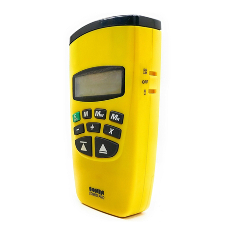
Sonin RANGE FINDER II User manual

- 1 - - 2 -
TABLE OF CONTENTS DESCRIPTION OF PRODUCT
DESCRIPTION OF KEY FUNCTIONS DESCRIPTION OF KEY FUNCTIONS
DESCRIPTION OF LCD DISPLAY
- 3 - - 4 - - 5 -
Introduction .................................................................... 1
Description of Product ..................................................... 2
Description of Key Functions ....................................... 3-4
Description of Display ................................................. 5-6
Gettin Started ............................................................ 7-8
Helpful Measurin Hints ................................................. 9
Computation Functions ............................................. 10-11
Memories ................................................................. 12-13
Troubleshootin ........................................................ 14-16
Specifications ................................................................ 17
Environmental Conditions ........................................... 18-19
FCC Note ....................................................................... 20
Customer Service ......................................................... 21
Warranty Information ...................................................... 22
Warranty Re istration Card ............................................. 23
INTRODUCTION
Thank you for choosin a SONIN Laser Tar etin Ran e Finder
LTRF. Your LTRF is recommended for INDOOR use only. To
ensure proper use of this product and to obtain optimum
performance, be sure to read this manual carefully before use.
CAUTION
This product contains Class II laser radiation, to avoid injury
to eyes DO NOT stare into the laser beam or project the laser
beam to other persons or animals.
Second Function Key
Activates the second function or stores a measurement
into user memories M1, M2 and M3.
Clear Display / Clear Memories /
Unit OFF
Press button once to clear current display and o back
to measure mode.
Press and hold 5 seconds to clear all memories, includin
user's memories M1, M2, M3 and the last 5 measurements.
After recallin M1, M2 or M3, press and hold this button 3
seconds to clear that memory.
Quickly press twice to turn OFF power when the current display
is cleared. Note: unit will automatically turn off in one minute
when idle.
C ange or Convert Display Units
Press [2ND] then press [CLR/UNITS] button
to chan e display units.
Turns ON Power and Takes
Measurements
Press and hold 1 second to turn ON power
when the power is OFF.
Press and release to take measurement.
C anges t e Measuring Position
Your LTRF is factory preset to measure from
the bottom of unit, if you want to chan e the
measurin position from top of unit, press
[2ND] than press the [READ] button. Note: The
setting will show in the left corner of LCD
Recalls t e Last 5 Measurements
Your LTRF automatically stores up to 5 previous
measurements. Press this button to recall those
measurements one by one on the LCD screen, the RCL icon
and upper di its will indicate the measurements sequence.
Sets t e Laser Pointer
Your LTRF is preset to measure with the laser
pointer on, you can also turn it off or reset the
laser pointer by pressin [2ND] then [RCL] button, the
icon will appear on the LCD only if the laser is on.
Adds Linear Distance, Areas and
Volume Measurements
Press this button to add linear distance or add
Areas and/or Volume measurements. The icon will appear
on the upper corner of LCD screen.
Subtracts Linear Distance, Areas
and Volume Measurements
Press [2ND] button then press [+] button to
subtract linear distance or Areas and/or Volume. The icon
will appear on the upper corner of LCD screen.
Multiplies Measurements for Area
and Volume
Press to compute Area or Volume measure-
ments. The icon will appear on the upper
corner of LCD screen.
Recalls Measurement from Users
Memories
Press [M1], [M2] or [M3] to recall stored
data from that memory. The memory icon
will blink to indicate the readin was recalled
from memory.
Stores Displayed Measurement in
to Users Memories
Press [2ND] then press [M#] button to store
displayed measurement into that memory. The
memory icon will appear on LCD indicatin
the measurement is stored into that memory.
RCL
M1 M3M2
STORE
2ND
CLR
UNITS READ
Laser Beam
Aperture
LCD
Display
Clear Display &
Chan e Display
Modes
Power ON &
Measure Key
Recall &
Laser ON/OFF Key
Store Memories &
Second Function Key
Multiplication Key
Add & Subtract Key
Users memories M1
M2 & M3
Ultrasonic
Aperture
#10275
Instruction Manual
Electronic Distance Measuring Tool
With Laser Targeting
Targeting
RANGE FINDER II
Laser
SONIN INC.
© 2006 SONIN Inc. All Ri hts Reserved
Printed in China
P/N: 275-1400-0070 REV.3
www.sonin.com
English
DESCRIPTION OF KEY FUNCTIONS
123456789
11 12
10
13 14

To preform the computations as described below, the [READ]
button symbol indicates takin an actual measurement (len th,
width or hei ht).
Adding Distances:
The display shows the total distance. Continue until you are
done addin measurements.
Subtracting Distances:
The display shows subtracted distance. Continue until you are
done subtractin measurements.
Multiplying to compute Areas:
Display shows square (SQ) measurement.
Multiplying to compute Volumes:
Display shows cubic (CU) measurement.
To Add Areas:
Area 1
Area 2
Display shows total area. Continue until you are done addin
areas.
To Add Volumes:
Volume 1
Volume 2
Display shows total volume. Continue until you are done addin
volumes.
Remarks: You can also compute Distance Area and Volume
between memories M1 M2 and M3
For example: Addin distances between memories M1 and
M2. Store 2 distances into M1 and M2 before calculation,
then press:
For example: Compute Area or Volume between memories
M1, M2 and M3. Store 3 distances (len th, width and hei ht)
into M1, M2 and M3 before calculation, then press:
For example: Addin 2 Area between M1 and M2.
Store 2 Area measurements into M1 and M2, then press:
The display shows total Area.
- 6 - - 7 - - 8 -
- 9 - - 10 - - 11 -
DESCRIPTION OF LCD DISPLAY GETTING STARTED / QUICK START GETTING STARTED / QUICK START
HELPFUL MEASURING HINTS COMPUTATION FUNCTIONS COMPUTATION FUNCTIONS
1. Icon indicates the measurin position.
2. Icon indicates measurement in process.
3. Icon indicates the Laser settin s.
4. Icon indicates the 2ND function key pressed.
5. Icon indicates users memories in use.
6. Icon indicates measurement recall.
7. Di its indicate temperature readin and number of recall.
8. Temperature display units.
9. Battery low indicator.
10. Icons for calculatin functions in process.
11. Cube and Square measurements.
12. Measurement units.
13. Six di its of main display.
14. Indicates Fraction of an inch in feet/inch mode.
DISPLAY MODES
Four display modes are available. To chan e or convert the
displayed value to your desired units, press [2ND] then
[CLR/UNITS] button, the displayed value will chan e to other
units. Repeat until you reach the desired mode.
Chan e Unit
1) Install a fresh 9V
alkaline battery in rear
of unit. Push contacts
firmly in place.
2) Press [READ]
button one second to
turn ON unit. The LCD
screen will show the
display units, current
temperature,
measurin position and
the laser settin .
3) Aim cone at a hard, flat, unobstructed surface such as a
wall or floor, and make certain you have a clear path to the
surface (wall).
4) Hold your LTRF perpendicular to the surface to which you
are measurin .
5) Press [READ] button to take a measurement. When takin
a measurement, the laser pointer will indicate the approximate
center of the tar et area for your reference.
Note: the laser pointer is a factory set function however
you can turn it off or reset by pressing [2ND] and [RCL]
buttons.
6) Your LTRF may be factory preset to display in Feet-Inch-
Fraction mode. To set the display to your desired mode, press
[2ND] then press [CLR/UNITS] button to chan e the display
units between Feet-Inch-Fraction, Decimal Feet, Yards or Meters.
NOTE: Unit will now default to your set mode until battery is
removed.
1) Remember your LTRF is
preset to measure from the
BOTTOM of the unit
(Measurement displayed is from
bottom of unit to the tar et
surface). If you need to measure
from the TOP of the unit, press
[2ND] then press [READ], the
settin will appear on the upper
left corner of the LCD.
2) Measurements cannot be taken throu h lass or off of soft
or padded surfaces.
3) The LTRF ran e and ability to measure in ti ht spaces can
be increased. Stand in the middle of the distance to be measured
and add measurements taken in opposite directions.
4) When measurin in confined spaces (hallways), try to
measure down the center line and midway between the floor
and ceilin .
5) When the surface bein measured to has protrusions and
recesses, you can determine where the beam is hittin . Move
sideways, parallel to the tar et, then try a ain, you will see the
distance increase for recesses and decrease for protrusions.
6) Be sure the surface you are measurin to is hard, flat and
uniform. Some surfaces such as stucco or clapboard may
scatter si nals.
FEET-INCH-FRACTION DECIMAL FEET
YARDS METERS
YES NO YES NO
Measure from
top of unit.
Measure from
bottom of unit.
The sound waves emitted from this unit
spread 1 ft (30 cm) for every 10 ft (3m) measured.
Laser is for reference only.
RCL
M1 M3M2
STORE
2ND
CLR
UNITS READ
Measure from
TOP of unit
Measure from
BOTTOM of unit
1 Second

- 12 - - 13 - - 14 -
- 15 - - 16 - - 17 -
MEMORIES MEMORIES TROUBLESHOOTING
TROUBLESHOOTING TROUBLESHOOTING SPECIFICATIONS
RANGE:
Min: 1 ft 5 ins or 0.43 meter (from top of unit)
Max: 60 ft (18.2 meter)
Actual: Will vary dependin on environmental conditions.
ACCURACY: 99.5% ± 1/4 in (or 99.5% ± 1 cm)
When environmental conditions are as follows:
Temperature: 32 to 86°F (0 to 30°C)
Relative Humidity: 30 to 70%
Altitude: -328 to +328 ft (-0.1 to 0.1 km )
Wind Speed: Still Air
Examples: At 15 ft (4.57 M) your readin will be within
1-1/4 inches (3 cm). And at 60 ft (18.2 m) your readin
will be within 3-3/4 ins (10 cm).
RESOLUTION: 1/4 inch (or 1 cm, or 0.01 feet or 0.01 yard)
ULTRASONIC FREQUENCY: 40 kHz
LASER POINTER:
Type of Laser: Semiconductor laser module
Wavelen th: 650 nm
Output Power: Less than 1mW (Class II)
Safety Standards: Complies with 21CFR 1040.10
and 1040.11
OPERATING VOLTAGE: 9 volt battery (alkaline recommended)
CURRENT CONSUMPTION:
Standby mode: less than 10 µA
Measure without laser: Approx. 15 mA
Measure with laser: Approx. 30 - 40 mA
OPERATING TEMPERATURE: 32 to 100 °F (0 to 38 °C)
STORAGE TEMPERATURE: -14 to 140 °F (-10 to 60 °C)
AUTO SHUTOFF TIME: Approximately 1 minutes after
last key is pressed.
DIMENSION: 4-3/4 x 2-3/8 x 1-1/2 ins (121 x 60 x 37 mm)
WEIGHT: 3 oz (85 m) without battery
To Clear a Measurement in Memory M1 t ru
M3:
After recallin the memory, press and hold [CLR/UNITS] button
for 3 seconds to clear that memory. The memory icon will
disappear.
Example: Clear Measurement in M1
To Recall t e Last Five Measurements:
To recall up to the 5 last measurements one by one, press the
[RCL] button, the LCD will display
to indicate that memory.
To Clear All Memory
From the on position, press and hold [CLR/UNITS] button 5
seconds to clear all memories, includin M1, M2, M3 and 5
last measurements.
Your LTRF has 3 user memories (M1, M2 and M3) and 5
memory re isters to automatically store and recall your last 5
measurements. Three user memories allow users to store Liner,
Square or Cube measurements, and the compute functions
available for those memories includin Addition, Subtraction
and Multiplication.
To Store Measurements into Memory M1 t ru
M3:
Press [2ND] then press [M1] or [M2] or [M3] button to store
the displayed measurement in that memory, the memory icon
will appear on the LCD screen once stored.
Example: To store distance in M1
Example: To store Area in M2
Example: To store Volumes in M3
Note: Storing a new measurement into memories will replace
the old one.
To Recall Memory from M1 t ru M3:
Press [M1] or [M2] or [M3] button to recall measurement in
that memory directly, the memory icon will blink to indicate
which memory was recalled.
Interference from external noise sources (see section on
Environmental Conditions).
Unit was moved durin the measurement. The unit must be
held stationary.
Error 3
Math error or result overflow.
2) If you et readin s which are excessively lon or short,
the likely causes are:
a) The unit is not bein held parallel to the floor. Hold the
unit parallel to the floor and at 90° to the surface bein
measured to.
b) Measurin path is not clear of obstructions or it is not
wide enou h.
c) The surface you are measurin to is not sufficiently flat
and the sound waves are continuin to rebound. Place a
flat object, such as a board or mirror a ainst the surface
and measure to the object.
d) Environmental factors such as noise from machinery
or close proximity to an air conditioner or computer screen.
3) If you et readin s that are too short for the distance bein
measured, make sure there is a clear and sufficiently wide path
to the surface. Remove any objects in the way or select a
different surface to measure to.
4) If your laser does not display when takin a measurement,
it may be turned off. Check LCD to see if ( laser icon ) is
displayed. If it is not. press [2ND] and [RCL] to turn on laser.
1) If the LTRF is unable to take a " ood" measurement the
display will show one of the followin :
BLANK SCREEN
When the unit cannot turn ON by
pressin the [READ] button, check
and replace the battery. If unit still
doesn't work, call SONIN Technical
Support at (800) 223-7511.
BATTERY LOW SYMBOL
When the battery low symbol
appears on the upper ri ht corner
of the display, replace the battery.
Measuring Distances Too S ort
Your measurin distance must be
lon er than 1 foot 5 inches from
top of unit or 1 foot 10 inches from
bottom of unit.
Error 1 Possible causes for
Error 1 include:
Measurement out of ran e or no
return si nal.
Unit is not perpendicular to the
surface.
Surface is not hard and flat.
Error 2 Possible causes for
Error 2 include:
No valid readin (Multiple object
detected).
5) Ran e and accuracy can be affected by environmental
factors such as wind, temperature, humidity and altitude (see
section on Environmental Conditions).
VERIFY TEMPERATURE TO IMPROVE
ACCURACY
Because temperature affects the speed of sound, the LTRF has
automatic temperature compensation for reater accuracy. In
order to make the most of this feature, verify the internal
temperature on the upper corner of LCD screen. If it does not
match the air temperature, wait 1 minute for each 1°F (or 2
minutes for each 1°C) of temperature difference between cool
and warm locations. See "TEMPERATURE" in the section on
Environmental Conditions.
Note: The temperature displays in °F when imperial modes are
selected, or in °C if metric mode is selected.
The minus si n - will alternately display with the readin
when the temperature is less than zero.
The readin 1 will separate and alternately display when the
temperature is over 100 °F.
3 Seconds

- 18 - - 19 - - 20 -
ENVIRONMENTAL CONDITIONS THAT COULD
AFFECT PERFORMANCE
IMPORTANT
Ultrasonic Distance Measurin Tools work best for quick and
easy measurin and estimatin . They are not intended for
precision work, althou h they can be very accurate under
optimal conditions.
HUMIDITY
Humidity and temperature can affect the ran e and accuracy
of all ultrasonic distance measurin tools. They may ive
measurements that are lon er or shorter than their specifications
(dependin on atmospheric conditions). The ran e is lon est
in hi h temperature/hi h humidity and low temperature/low
humidity and ran e is shortest in hi h temperature/low humidity
and low temperature/hi h humidity.
Humidity effects on accuracy are reatest at hi h temperatures
and ne li ible at low temperatures. At 100°F (38°C) and 99%
R.H., the distance measurement will be short by 0.6%. At 100°F
(38°C) and 0% Relative Humidity, the distance measurement
will be lon by 0.6%. At 32°F (0°C) the distance measurement
will essentially not be affected.
TEMPERATURE
Your LTRF has unique automatic temperature compensation to
ensure consistency of measurements between 32°F and 100°F
(0°C to 38°C). The response rate of this circuitry enables you
to move between warm and cold areas and measure with
reasonable accuracy. However, we recommend that you do not
leave your SONIN unit in very cold or very hot conditions (e. .
sunli ht in a car), as the unit will then require more time to
ENVIRONMENT CONDITIONSENVIRONMENT CONDITIONS
Your SONIN Laser Tar etin Ran e Finder is warranted a ainst
defects in workmanship and materials for one year from date
of ori inal purchase.
Dama e while in the possession of the consumer, not resultin
from a defect in materials and workmanship, and dama e from
other than normal use, includin misuse, abuse, alternation
and repair by unauthorized parties, is not covered by this limited
warranty, nor does it cover the battery.
THIS WARRANTY IS EXPRESSLY IN LIEU OF ALL OTHER
WARRANTIES, EXPRESSED OR IMPLIED, ARISING BY LAW OR
OTHERWISE, AND IS MADE ON THE EXPRESS
UNDERSTANDING THAT THE ITEMS SOLD UNDER THIS
CONTRACT ARE PURCHASED BY THE BUYER "AS IS" AND
THAT THERE IS NO IMPLIED WARRANTY THAT THIS
INSTRUMENT SOLD TO BUYER SHALL BE MERCHANTABLE
OR AN IMPLIED WARRANTY THAT IT SHALL BE FIT FOR ANY
PARTICULAR PURPOSE OR USE. THE BUYER ACKNOWLEDGES
THAT HE (IT) IS NOT RELYING ON THE SELLER'S SKILL OR
JUDGEMENT TO SELECT OR FURNISH ITEM OR ITEMS SOLD
AND THAT THERE ARE NO WARRANTIES WHICH EXTEND
BEYOND THE DESCRIPTION ON THE FACE THEREOF. THE
BUYER HEREBY WAIVES ALL OTHER REMEDIES' WARRANTIES
AND GUARANTEES WITHOUT LIMITATION, INCLUDING
CONSEQUENTIAL DAMAGES.
To qualify for replacement of this item, which is the exclusive
remedy available from SONIN, within one year from purchase
under this limited warranty, the ori inal Buyer shall 1) Mail this
warranty coupon within 30 days of date of purchase, properly
filled in 2) as his/her cost, return the defective unit with proof
of purchase within one year from date of ori inal purchase to
your SONIN dealer for repair or replacement. SONIN will repair
or replace the instrument at SONINs option and return it with
prepaid frei ht to the dealer.
This device has been tested and found to comply with the limits
for a Class B device, pursuant to part 15 of the FCC Rules.
These limits are desi ned to provide reasonable protection
a ainst harmful interference in a residential installation. This
device enerates, uses and can radiate radio frequency ener y
and, if not used in accordance with the instructions, may cause
harmful interference to radio communications. However, there
is no uarantee that interference will not occur in a particular
installation. If this equipment does cause harmful interference
to radio or television reception, which can be determined by
turnin the device off and on, the user is encoura ed to try to
correct the interference by one or more of the followin measures:
- Reorient or relocate the receivin antenna
- Increase separation between the device and receiver
This Class B Di ital Apparatus meets all requirements of the
Canadian Interference-Causin Equipment Re ulations.
DISCLAIMER:
The SONIN Laser Tar etin Ran e Finder employs a sonar
method of measurement. The laser pointer in this unit is for
reference purposes only, and is not part of the measurin
apparatus. The laser pointer indicates the approximate center
of the tar et area to which measured. The laser pointer neither
measures, nor increases the accuracy of measurement performed
by the unit usin sound waves. The accuracy of this measurin
device is 99.5% ±1/4" of the distance measured.
FCC NOTE
WARRANTY INFORMATION
adjust to air temperature. As lon as the internal temperature
is equal to the air temperature, accuracy is unaffected. Wait for
the unit's internal temperature to equal the air temperature or,
add 1% of the measured distance for each 10°F (5.5°C) that
the measured temperature is below the actual temperature;
subtract 1% of the measured distance for each 10°F (5.5°C)
that the internal temperature is above the air temperature. (See
section on VERIFY TEMPERATURE TO IMPROVE
ACCURACY for instructions on how to obtain a temperature
measurement from your SONIN Laser Tar etin Ran e Finder.)
ALTITUDE/BAROMETRIC PRESSURE
Altitude and barometric pressure can affect the ran e and
accuracy of all ultrasonic distance measurin tools.
As the altitude increases (barometric pressure decreases), the
ran e is reduced. As altitude decreases (barometric pressure
increases), the ran e is increased. To correct for altitude
(pressure) effects on accuracy, subtract 0.4% of the measured
distance for each 1000 ft/ -0.06" H (0.3 km /-15mm H ) you
are above sea level. Add 0.4% of the measured distance for
each 1000 ft/ +0.06" H (0.3km /+15mm H ) you are below
sea level (sea level = 760mm H ).
NOISE
Hi h frequency noise from machinery, en ines, computers,
stereos, TV sets, etc. can affect the readin and you may et
random readin s. Stand away from or shut off this type of
equipment when measurin .
OUTDOOR MEASUREMENTS
Your Sonin Laser Tar etin Ran e Finder is desi ned for indoor
use only.
WARRANTY REGISTRATION CARD
DETACH AND MAIL TO:
SONIN Inc.
15105-D Jo n J. Delaney Dr. Suite 333,
C arlotte, NC 28277, USA
IMPORTANT! Please return this warranty re istration card
within 30 days to insure that your new SONIN Laser Tar etin
Ran e Finder is covered by the limited warranty explained
above.
CUSTOMER SERVICE
- 21 -
Purchaser's Name
Address
City
State Zip
Purchase Date
here Purchased
Store Name
Address
City
State Zip
Model: 10275
Laser Targeting Range Finder II
Serial No.:
CUSTOMER SERVICE
SONIN takes pride in offerin unmatched customer service to
owners of SONIN products. If you have any questions or would
like additional information,
please call 1- 800 - 223 7511 (USA)
or e-mail to [email protected]
TECHNICAL ASSISTANCE
If you have any questions or need technical assistance,
e-mail to technica [email protected]
Table of contents
Other Sonin Analytical Instrument manuals
