Neutronics NTRON PureN2 User manual

A DIVISION OF
456 Creamery Way, Exton, PA 19341
www.neutronicsinc.com
High Purity Instruments
MODEL N2
OPERATIONS MANUAL
Document Control Number: MN-A-0119
Manual Part Number: C5-06-4900-13-0
Revision Level: F Date: Oct. 31, 2006
ECO: 7988
Engineered Solutions for Gas Detection and
Analysis

Introduction
Thank you for your purchase of the PureN2 Pump Drive,
High Sensitivity Parts Per Million Oxygen Analyzer .
ThePureN2 PPM Oxygen Analyzer is a user friendly,
microprocessor controlled, oxygen measuring system. It
has many features to offer the user which will be described
in this manual. We recommend that all personnel who use
this instrument read this manual to become familiar with
the instrument's operation.
If you have any questions or concerns while using the
PureN2, please contact us.
Neutronics /Ntron Customer Service Department
456 Creamery Way
Exton, PA 19341
610-524-8800
610-524-8807 (f)
(800)-378-2287 Toll Free (US only)
visit at www.neutronicsinc.com (web site)

Neutronics Inc.
Warranty Statement
Neutronics warrants to the original purchaser, that the Model PureN2, P/N C7-01-1000-16-0 Oxygen
Analyzer to be free from defects in material and workmanship for a period of one (1) year from the date of
shipment from Neutronics or from one of Neutronics’ authorized dealers. Our liability will be limited to
the repair or replacement, at our factory, of parts found to be defective within the warranty period, as
determined by Neutronics. The parts will be repaired or replaced free of charge if shipped prepaid to the
factory in the original shipping carton. This warranty is void if the product has been subject to misuse or
abuse, including but not limited to: exposure to water, humidity- temperature- shock or pressure outside
of the listed specifications, or has not been operated in accordance with operating and maintenance
instructions, for repairs which were not performed by Neutronics or by one of its authorized dealers, or if
the identifying markings on the product label have been altered or removed.
The seller assumes no liability for consequential damages of any kind, and the buyer, by acceptance
through purchase of this product, will assume all liability for the consequences of its use or misuse by the
buyer, his employees, or others.
Neutronics reserves the right to use any materials in the manufacture, repair or service of the products and
to modify the design as deemed suitable, in so far as these materials or modifications maintain the stated
warranty.
It is the sole responsibility of the buyer / user to determine if this product is suitable for the intended
application.
THESE WARRANTIES ARE EXCLUSIVE AND IN LIEU OF ALL OTHER WARRANTIES,
EXPRESSED, OR IMPLIED INCLUDING WARRANTY OF MERCHANTABILITY, FITNESS FOR
A PARTICULAR PURPOSE.
Intended Use and Important Notes for the
Application of the Model PureN2
The model PureN2 oxygen analyzer was designed to provide the trained operator with useful information relating
to the concentration of oxygen. This information may be used in process control or to minimize possible
hazardous conditions which may be present in various processes. Before implementation, the user must fully
understand the operation and limitations of this instrument as well as the application for its use. The responsibility
for the proper application, operation, and maintenance of the model PureN2 oxygen analyzer is the sole obligation
of the trained operator. The purchaser is required to ensure operators are properly trained in the use of this unit as
well as in the possible hazards associated with its use or with the intended application. The purchaser must ensure
that all of the proper warnings, labels, instruction manuals, lock outs, redundant components, hazard analysis, and
system validation have been completed and provided to the trained operator before implementation of the model
PureN2 instrument.

For Your Safety:
PLEASE
•READ THIS MANUAL IN ITS ENTIRETY BEFORE ATTEMPTING INSTALLATION
OR OPERATION!
Attempting to operate the Model PureN2 without fully understanding its features and
functions may result in unsafe conditions.
•Always use protective eye wear and observe proper safety procedures when working with
pressurizedgases.
•Always assure the pressure of gas entering the Model PureN2 is in the range of 2mm Hg
vacuum to 250mm Hg positive pressure (gage pressure) .
•Always calibrate the Model PureN2 at an equivalent pressure and flow rate to the gas being
measured.
•Always allow the Model PureN2 sensor to cool down before attempting to access the sensor.
•Ensure the MODEL PureN2 has been properly calibrated before use.
•Never expose the analyzer chassis or sensor to water, high humidity or moisture. The
analyzer chassis is not watertight.
•Never expose the MODEL PureN2 to flame or high temperatures.
•Never expose the MODEL PureN2 directly to unregulated gas lines, cylinder gas, …
•Ensure the analyzer unit is mounted in an area of free air flow to prevent the chassis from
exceeding the operating temperature specifications. Do not set the analyzer against hot
surfaces. Do not block the ventilation louver on the analyzer chassis.
COPYRIGHT NOTICE:
Copyright ©2006 Neutronics Inc.
This work is protected under Title 17 of the US Code and is the sole property of Neutronics Inc. No part of this document may
be copied or otherwise reproduced, or stored in any electronic information retrieval system, except as specifically permitted
under US copyright law, without the prior written consent of Neutronics Inc.
!

Table of Contents
Specifications
Chapter 1 Basic Principles of Operation ………………………………….. 3
Description
Theoretical Basis
System Components
The Sensor and Sampling System
Electronic/Display System
Furnace/Heater
Sampling System
High Purity Pump
Chapter 2 Installation and Start-Up ……………………………………………. 8
Installation and Hook-up
Start-Up
Special Situations
Chapter 3 Operation ……………………………………………………………… 10
Display
Optional Modes
Calibration Mode
CleanMode
Display Cell EMF
List Analog Output Range
Set the Calibration Air Partial Pressure Value
Set the Cal Gas Partial Pressure Value
Set Alarm Values
Display the Temperature
Communications Interface
Serial Interface using MICRODOFT WINDOWS Hyperterminal
Chapter 4 Calibration ……………………………………………………………… 14
Chapter 5 Analog Output …………………………………………………….. 16
Chapter 6 Alarm Functions …………………………………………………….. 17
Dry Contact Closures
Chapter 7 Trouble Shooting …………………………………………………….. 19
Error Codes
Parts List ………………………………………………………………………………..
21
Maintenance ……………………………………………………………..……….. 22
Sensor Signal Output Reference Chart ……………………………………………. 23
Changes may be made to this manual and to the specifications of the PureN2 PPM Oxygen Analyzer without notice.

Specifications
Dimensions 14.75" High x 9" Wide x 13.55" Long
(375 mm x 229 mm x 344 mm)
Weight 12 lbs. (5.5 Kg)
Operating Conditions Ambient Temperature: 0 to 122ºF (0 to 50ºC)
Relative Humidity: 0 to 90% (Non-Condensing).
Range Auto-ranging between .001 PPM to 99.9% O2. Operator does not need to select
the range. Indicator light specifies whether the reading is in percent or ppm.
Accuracy 1 to 100 ppm +/- 5% of reading
101 to 999 ppm +/- 2% of reading
.1 to 99.9 % +/- 2% of reading
Response Time
Change response: 95% of step change in 5 seconds at 1 liter/min. sample flow rate.
90% of step change in 10 seconds below 999 PPM.
Recovery Time From Room Air To . 1 PPM ~5 min
50 PPM < 15 seconds
.1%<5sec
.
Operations Pressure = 10mm Hg vacuum to 250mm Hg positive pressure (gage pressure)
regulated to constant pressure.
Flow rate = .5 to 1.5 liters/min.
Warm-up Time Approximately 20 minutes
Power Supply 115 VAC +/- 20%
50 to 60 Hz Single phase
(Selectable to 220 VAC operation with a change of internal and external switches).
Outputs 3-digit LED Display
RS-232 Computer communications of the following data:
Percentage, ppm, cell temperature, cell voltage, high/low alarm.
Analog Output - Auto-ranging or operator may select ranges.
0 to 1+/-.5% VDC @ 10K input impedance minimum and a non-isolated
4 to 20+/-1% mA current output. Loop is powered by PureN2, negative
ground.
Hi/Lo Alarms Operator selects high and low set-points with option key.
Contact Relays Two available, 5 Amp @ 220 VAC rated.
Sampling System 316 S.S. Swagelok™fittings and tubing, 316 SS / Teflon Diaphragm / Viton Seals
High Purity Pump, 1 carbon cartridge filter supplied with unit.

3
CHAPTER 1
Description
The Model PureN2 is a microprocessor based portable instrument intended to accurately measure
oxygen in the range of 100% to 0.1 PPM. At the heart of the PureN2 is the Neutronics
Industrial/Ntron exclusive Rapid Response Zirconium Oxide Sensor. Because the sensor is a solid
state device, it offers many unique advantages over other sensor technologies.
•Rapid response: from air to 50 ppm in less than 15 seconds
•Wide measurement operating range: 100% to 0.1 ppm
•Immune to oxygen shock: can be exposed to air and within seconds read ppm
•Unaffected by position or motion
•Can be exposed to a wide range of operating gas temperatures
•Long Life (5-10 years expected) Low maintenance: no regular service required
The PureN2 offers two displays: a large LED digital display of oxygen concentration and a Dot
Matrix display to guide the user through modes of operation and diagnostics. The PureN2 also
offers a state of the art microprocessor based electronics with user friendly software interface via an
easy to use keypad.
The Model PureN2 operates on 110/220 VAC 50/60 Hz. Power source. A power cord is provided
for connection into a standard U.S. socket.
The Model PureN2 analyzer is supplied with a built-in high purity sample pump. The pump is an
oiless type, manufactured of high quality materials for use in a variety of applications where the
sample gas must be extracted from a process point. Because of the unique design, the PureN2 may
be used in applications including:
•Solder Reflow Ovens
•Wire Annealing
•Metal Heat Treating
•Glove Boxes
•Crystal Growth Chambers
•RTP Furnaces
•High Purity Welding Chambers
•High Purity Orbital Welding of SS or Titanium Tubing
•Aerospace
•Laboratory Use
To better understand the operation and maintenance of the Model PureN2 oxygen analyzer, please
read this manual in its entirety

4

5
Principles of Operation
Theoretical Basis
The sensor used in the PureN2 PPM Oxygen Analyzer is made of the solid state oxygen ion
conducting (electrolyte) zirconium oxide. Due to oxygen vacancies in the ceramic lattice, at
temperature over 450 degree Centigrade, oxygen ions are mobile in the solid material. It is this
property that enables the measurement of oxygen in a gas of unknown composition. When two gases
of differing oxygen concentrations are on opposite sides of a zirconium oxide membrane, each side
with a conductive (platinum) electrode material, a DC voltage is generated that is a function of the
difference in oxygen concentration. In practice, one side of the membrane is a known reference gas,
typically air, and the opposite side is the unknown sample gas to be measured.
In 1899 Nernst defined the relationship between the measured voltage and the unknown oxygen
concentration:
E=(RT/nF)ln(P1/P2)
Where:
E is the measured voltage.
R universal gas constant 8.314 joule/mole oK.
T is the temperature in oK.
n is number of electrons transferred (4).
F Faraday's constant 96,500 coul./mole.
P1 - Oxygen partial pressure in air reference (20.9% O2).
P2 - Oxygen partial pressure in sample gas.
Using this relationship, the unknown oxygen concentration can be determined by simply measuring
the voltage across the cell. Once the sensor is heated to a temperature of 725oC, the voltage is
measured, and the oxygen concentration information is sent to the display and other outputs. The
instrument is calibrated using air and a low level calibration gas for improved accuracy. This
calibration corrects for small effects of non-ideal sensor behavior.
Due to the high operating temperature and use of platinum electrode, the presence of reducing agents
such as hydrocarbons, carbon monoxide, hydrogen etc. interferes with the measurement of oxygen.
The analyzer will display lower than actual oxygen concentration in the presence of reducing agents.
(For example: 2 H2plus 1 O2forms 2 H2O and thus reduces the O2the analyzer reads by a ratio of
0.5 for every 1 H2molecule. 2CO plus 1)2forms 2CO2which also reduces O2o.5 for every 1 CO
molecule. Data shows that hydrocarbons reduce O2by 0.1 for every hydrocarbon molecule.)
Caution should be taken to use the OA series analyzers to measure inert gases only. Do not
attempt to measure gases containing sulfur gases like H2S. The sulfur reacts with the platinum
electrode to form platinum sulfide. This reaction degrades the electrochemical properties of the sensor.

6
System Components
The four basic components in the analyzer are described below and shown schematically in Fig.# 1.
Sensor
The solid electrolyte (Zirconium Oxide) electrochemical sensor consists of a closed end ceramic
(Zirconium Oxide) tube coated inside and outside with two porous platinum electrodes. When
heated above 600oC ionic conductivity of the Zirconium Oxide becomes high enough to generate a
voltage as described by the Nernst equation. The outside electrode is exposed to air and acts as a
reference. The sample gas flows inside the tube and the inner electrode acts as the sensing electrode.
The sensor measures oxygen partial pressure and the voltage output is affected by the change in total
pressure. To reduce sensor error, maintain the outlet at approximately ambient pressure.
The sample gas flow into the analyzer is controlled at a rate on .5 to 1.5 liter(s)/minute by a needle
valve and rotometer on the front of the analyzer. The outlet must be maintained at approximately
ambient pressure to insure sensor accuracy. Included in this part of the system is an O-ring fitting
which connects the electrochemical sensor tube to the rest of the sampling system; specifically the
gas sampling inlet and outlet tubes.
Electronics/Display System
The microprocessor-based system controls the operation of the PureN2 PPM Analyzer and displays
relevant information. It consists of a CPU board, an Analog board, a Power Supply board and a user
interface board with LED display, LCD display, and a control key pad.
Furnace/Heater
This is the metal box within the instrument which is an electrical resistance heater. It heats the
electrochemical ceramic sensor to the operational temperature of 725oC. It also has a type K
thermocouple to sense temperature for controlling the furnace.
Sampling System
The PureN2 consists of a high purity pump which extracts a gas sample from the process point. The
gas is pressurized and directed to a tubing junction. The gas is directed in two directions: one
through a bypass valve as a slipstream; the remaining gas is directed through a fixed orifice to the
sensor. The pressure release bypass valve controls system back pressure onto the sensor and also
allows a slipstream flow (for faster response time). The fixed orifice is used to reduce the
pressure/flow of the sample gas as it flows to the zirconia sensor. Gas released by the bypass valve
exhausts through the outlet fitting, while the sample stream (approximately 120 cc/min) is
discharged through a bulkhead fitting outside the back of the analyzer.

7
PureN2 PPM O2ANALYZER SYSTEM CONFIGURATION
FIGURE 1
ANALOG
BOARD
CPU
BOARD
DISPLAY
BOARD
KEY PAD
POWER
SUPPLY
POWER
FILTER
SENSOR
TC
FURNACE
ISOLATOR
BOARD
(OPTIONAL)
SAMPLE FLOWMETER
BYPASS
CHECK
VALVE
PUMP
SENSOR
EXHAUST
SAMPLE INPUT
BYPASS
EXHAUST
ISOLATED 4-20 mA
OUTPUT
4-20 mA OUTPUT
ANALOG mV
OUTPUT
VAC POWER
INPUT
RELAY ALARM
OUTPUTS
RS-232 SERIAL
PORT
VAC POWER
INPUT

8
CHAPTER 2
Installation and Start-up
Installation
The PureN2 Oxygen Analyzer is a completely self contained instrument. The only requirement to
operate it is a source of power. Set selector switches on the rear of the unit to the 110 setting for 120
VAC + 20%, or the 220 setting. Internal and external switch changes are required for 220 VAC.
Contact Neutronics for instructions. This analyzer has been designed for analyzing O2in clean gases
that contain no hydrocarbon or CO components.
The PureN2 Oxygen Analyzer utilizes 1/4 inch Swagelok fittings and connections throughout the
system. Inlet and outlet ports are located as shown in Fig 2. The ports are 1/4 inch tube Swagelok
fittings. Gas inlet flow requirements are .5 to 1.5 liter(s)/minute. A flow control valve is supplied in
the front panel with a rotameter to indicate flow rates of gas being supplied to the analyzer.
FIGURE 2

9
Start-up
When the instrument is connected to power and turned on, the green POWER indicator lights illuminate (main analyzer
power lamp & Pump power lamp), the electronic display illuminates, and the LED display counts up to test the LED
segments.
The warm-up time before the instrument is operational is approximately 20 minutes.
As the analyzer is warming up, the green READY light flashes and heater temperature is shown on the LED display. The
secondary display reads OVEN WARMING UP. When the sensor temperature reaches the operating range, the
secondary display reads STABILIZING. When the sensor temperature has stabilized the READY light stops blinking and
remains in a steady on state. O2concentration is shown on the LED display with the appropriate range light illuminated
(%, PPM).
Special Situations
When attempting to measure gases with oxygen concentrations of less than 10 ppm, the user must carefully evaluate the
entire system including the analyzer AND all external components such as gas plumbing, regulators, etc. It is important
to remember that all surfaces in contact with the gas to be measured will have some adsorbed oxygen on the surface.
Purging the system with the low-oxygen inert gas to be measured will eventually clean the surfaces of adsorbed oxygen.
Once cleaned, they will remain clean unless exposed to a high-oxygen gas such as air. The choice of gas line materials is
very important when measuring low ppm oxygen gases. For the best results, use cleaned stainless steel tubing.
Using the Pump / Filter Package Effectively
The PureN2 system is equipped with a built in high purity pump. The pump will allow sample to be drawn from ambient
air applications. The pump can also work with sample pressures ranging from a slight vacuum to positive pressure (see
specifications). The PureN2 system is also supplied with two carbon filters. The filters may be used for applications
such as solder reflow ovens where some contaminates may be present (flux, oils, etc…). Typically, one filter is installed
between the process point and the PureN2 analyzer. The second filter is held as a spare. In certain instances, both filters
may be installed. The primary filter will be installed close to the process point. The secondary filter will be mounted
close to the PureN2 analyzer.
Process Point
w/
contaminants
Primary
Filter
Secondary
Filter
10
CHAPTER 3
Operation
Display
The oxygen analyzer has a three-digit LED display for showing the temperature and oxygen content.
When the display is showing oxygen content, one of the range indicators is on. When the display is
showing temperature, the range indicators are off. The three digit display automatically switches to
the proper range to display the oxygen concentration of the gas being measured. The bottom range
indicator will illuminate to show parts-per-million range and the top indicates percent range. The
display automatically switches from percent to PPM when the sample oxygen concentration
decreases from .100% to 999PPM (.1% equals 1000 parts per million).
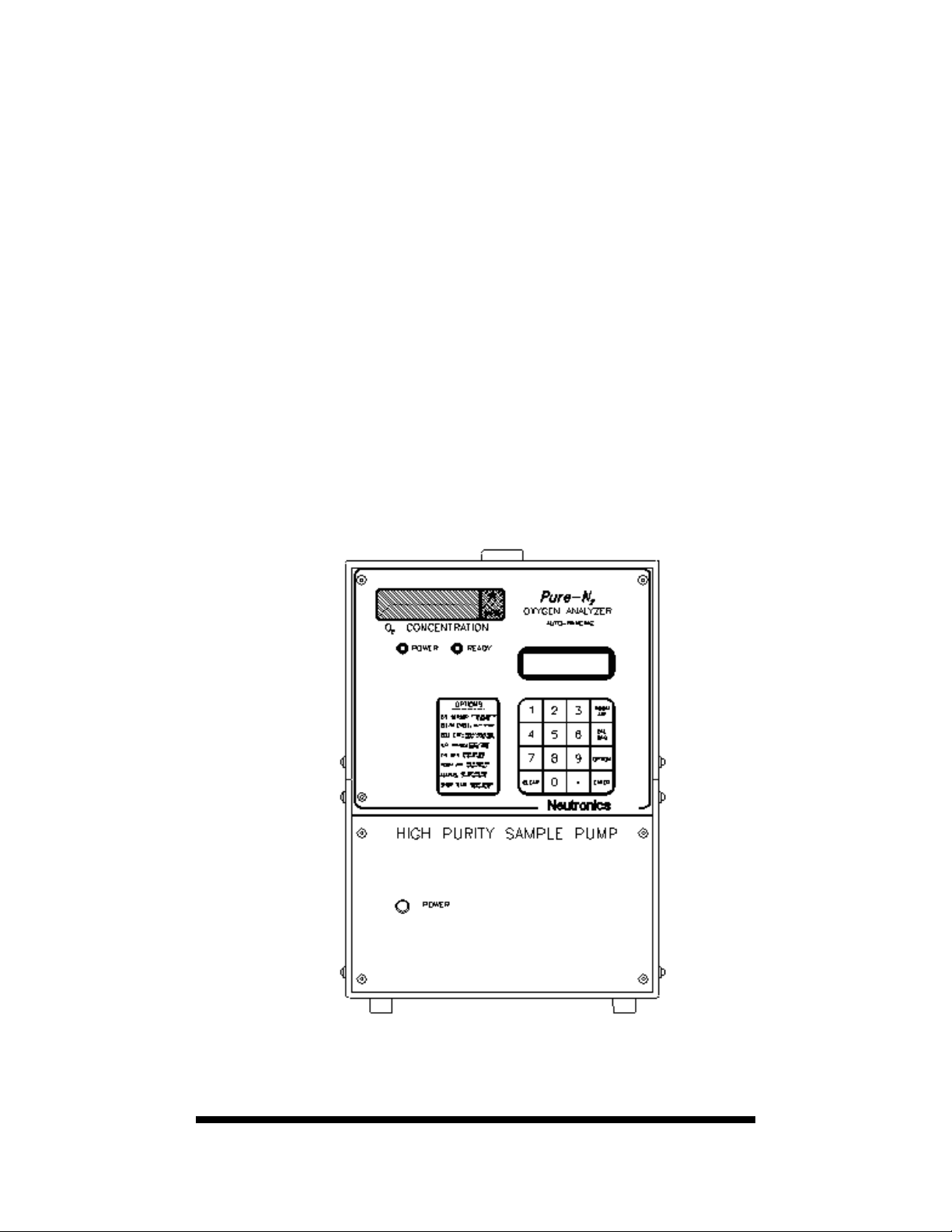
PureN2 FRONT PANEL
FIGURE 3

11
Option Modes
The PureN2 Oxygen Analyzer has several options. These options are accessed by using the OPTION key on
the keypad. The user scrolls through the options by pressing the OPTION key. Options are displayed on the
secondary display during scrolling. Choices are made by pressing the ENTER key when the desired option is
shown on the display. Brief descriptions of the options are printed on the front panel to the left of the key pad.
The option modes are described in more detail on the next page of this manual.
Calibration Mode
The secondary display reads "Cal Sensor?". This option allows the user to recalibrate the instrument.
Calibration steps are listed on the secondary display.
Clean Mode
The secondary display reads "Clean Cycle?". This option signals the device to pass oxygen from the reference
side of the sensor to the measurement side. This helps accelerate the combustion of impurities that may have
accumulated on the inner surface of the sensor.
Display Sensor Cell EMF Voltage
The Secondary display reads "Cell EMF?". This option lets the user see the actual voltage output of the
sensor cell. This function works like a digital volt meter.
List Analog Output Range
The secondary display reads "D/A Range?". This option lets the user select the range over which the analog
output(0-1 VDC or 4-20 mA) operates. The display will also read "Auto Range On" or "Auto Range Off"
depending on the operators specific selection. (See chapter 5)
Set the Calibration Gas O2Partial Pressure Value
The secondary display reads "Cal Gas?". This option lets the user see the entered value for the calibration gas
and change that value if required before calibration. This value is determined by the specification of the user's
calibration gas. Accuracy of the analyzer is a function of the accuracy of the calibration gas certification.
Values are entered in PPM O2.
Set the Room Air O2Partial Pressure Value for Calibration
The secondary display reads "List Room Air?". This option allows the user to see what value for room air has
been entered and change that value if required before calibration. Values are entered in % O2.
Set the Two Alarm Limits
The secondary display reads "Alarms?". The analyzer is equipped with the flexibility to set the alarms for
high/low, high/higher, low/lower as is needed for use in specific applications. The alarm option allows the
user to view the values and high/low settings that have been entered for the two alarms. When the oxygen
concentration goes outside the set alarm limits, the audible alarm sounds. This option also allows the user to
change alarm values and to turn the alarms on or off. Alarm contact relay #1 & relay #2 are located on the
back panel and will energize when the analyzer detects oxygen concentrations outside the alarm conditions.
Show Temperature
The secondary display reads "Show Temperature?". This option signals the analyzer to display the
temperature of the sensor cell heater in oC on the three digit LED display. Normal operation range is 725oC
+/- 5o.

12
Communications Interface
The electronics have been designed for communication with a host computer over a standard RS-
232 serial interface. The host computer can inquire about temperature, oxygen concentration, sensor
voltage, and other parameters. The host computer may control analyzer electronics, via the
communications interface, by turning the communications line on and off. It is recommended that
the communications line be turned off when not in use to speed up the analyzer's response time.
NOTE!! If a computer is on line with the analyzer, a restart may be accomplished either
by sending the analyzer a Ctrl-C instruction from the computer or by turning
the analyzer off and then on.
The commands are:
Limits
Letter Command Format Min Max Units
A Send Software Version x.xx 1.00 9.99 n/a
C Send Unit Configuration x 0 3 note#1
D Send Sensor Reading ppm xxxEsx 001E-3 999E+3 ppm
E Send Sensor Reading % xxxEsx 0.1 99.9 %
F Send Oven Temperature xxx 000 999 C
G Send Sensor Voltage sxxxEsx -999E-3 +999E-3volts
H Send Error Number xx 00 02 n/a
X Enable Communications Link via RS 232 port
x Disable Communications Link via RS 232 port
Z Send Error Message X n/a n/a Alphanumeric
Note: bit 0: 0=torr, 1=ppm bit 1: 0=air reference, 1=absolute reference
The communications Interface operates at 1200 Baud, 8 data bits, 1 stop bits, no parity. To operate
the interface, the host sends an ASCII command letter to the analyzer. The host computer then waits
for the analyzer to respond. The analyzer responds no later than 1.0 second after it receives the
command letter. All responses are terminated with a carriage return. Use the "X" command to start
continuous communication. O2concentration, in PPM with 1 decimal place (10.5 = 10.5 PPM),
will be sent out the RS232 to the host terminal every 1.5 seconds. To end the communication send
"x" (small letter x). The default at power up is communication off.
Cable requirements for two-way communications are a non-MODEM 25-pin female/male sub-D
connector terminated cable. The non-MODEM feature denotes that pins 2 and 3 are reversed on
each end. Currently, only 3 pins are used: pin 2=transmit, pin 3=receive, pin 7=digital ground.
When an alarm is activated, the analyzer sends, to the remote computer, either an "H" if the oxygen
concentration is above a HIGH alarm setting, or an "L" if the oxygen concentration is below a LOW
alarm setting. Alarm characters are also terminated with a carriage return and are sent once per
second as long as the alarm condition persists. If the analyzer receives a command while the alarm
is active, the alarm character is sent first followed by the command response.
Access to the Serial interface may made through a terminal emulator program such as HYPERTERMINAL
available in Windows 95:

13
Procedure for RS-232 Interface using
“HYPERTERMINAL” from Microsoft Windows 95
1. From the Windows menu, select “Start”.
2. Then, select “Programs”.
3. Then, select “Accessories”.
4. Then, select “HYPER TERMINAL”.
5. Double click on the HYPERTERMINAL Icon.
6. Choose name “Model PureN2”.
7. Choose code: none required.
8. Choose area code: none required.
9. ConnectUsing:
Direct to SERIAL COM 1 or SERIAL COM 2 (as applies)
BPS: 1200 BAUD
DataBits:8
StopBits:1
Parity: none
Flow Control: none
10. Click“OK”
Notes:
If serial communications has not been established with model PureN2 analyzer, make certain that the PC
SERIAL COM port is functional. This can be accomplished by jumping pins 2&3 on the RS 232 cable
leading to the PC. To accomplish this test, disconnect the RS 232 cable from the model PureN2 analyzer
port and insert a jumper between pins 2&3 on the cable connector or directly at the PC serial COM port.
Then, enter a letter from the PC keyboard : push an alpha-character key and then “enter” key. The PC
monitor should display the corresponding alpha-characters as they are typed. If the alpha-characters do
not echo on the monitor screen, there is a problem with the RS 232 cable, the PC serial COM port, or the
HYPERTERMINAL setup.
If the letter does echo on the monitor screen and serial communications with the model PureN2 analyzer
still has not been established, then pins 2&3 (xmtr & rcv.) may be reversed. First try reversing pins 2 & 3
on the RS - 232 cable connector. Then go back to the beginning of step #1 and try again. If the model
PureN2 analyzer still does not re-boot, call the Neutronics Industrial/Ntron Service Department for
further assistance.

14
CHAPTER 4
Calibration
The PureN2 Oxygen Analyzer is calibrated at the factory at a flow rate of 1 liter/min. It is important
to calibrate the device at your facility to compensate for atmospheric pressure variation between the
point of manufacture and the end use site. After completion of the calibration sequence, the display
readout will correspond to the cylinder analysis of the user's certified calibration gas.
Temperature
The Analyzer thermocouple is completely factory calibrated before shipping and requires no
calibration when received.
Sensor
To calibrate the zirconium oxide sensor, two reference points are required. The recommended
calibration procedure is to use compressed air and a calibration gas near your range of operation, as
the two reference points.
It is important to remember that the calibration will only be as accurate as the certification of the
reference gas you use.
The calibration sequence is semi-automatic. This means that the electronics adjust the offset and
gain, rather than requiring the user to adjust potentiometers. The user must flow gases as indicated
by the secondary display and push either the Room Air or Cal Gas buttons when the reading is
stable. This is two stage process that does not require repetition for both room air and calibration
gas.
See next page for detailed step by step Calibration Instructions.
NOTES:
It is best to calibrate the PureN2 Oxygen Analyzer at an identical flow rate for both calibration gases
and at the expected sample gas flow rate.
We recommend calibrating with room air first. When directed to "Flow 20.9% Gas" (on secondary
display), flow the room air or regulated source of instrument air. IT IS IMPORTANT TO
ALLOW THE READING TO STABILIZE before the ENTER key is pressed to complete the
calibration sequence.
Repeat this process using the low end O2concentration calibration gas to complete the two point
calibration. Flow the calibration gas from a cylinder of certified gas into the analyzer, ALLOW
THE READING TO STABILIZE, and press the ENTER key to complete the calibration.

15
STEP BY STEP CALIBRATION INSTRUCTIONS FOLLOW:
Step One: Be sure that the PureN2 Oxygen Analyzer has been warmed up for approximately
20 minutes before attempting calibration.
Step Two: Be sure the correct values for both Room Air and Calibration Gas are entered in the
device memory. Values may be viewed and changed if required by pressing the
ROOM AIR or CAL GAS key. The current value appears on the secondary display
with directions to "Press 1 To Change Value" or "Press Any Other Key To Accept"
the current value.
An alternate method to view and/or change the Room Air and Calibration Gas values
is to press the OPTION key until "Cal Gas?" or "Room Air?" appears on the
secondary display. Press the ENTER key to view. The current value appears on the
secondary display with directions to "Press 1 To Change Value" or "Press Any Other
Key To Accept" the current value.
Calibration gas and room air values may also be entered during the calibration
sequence. "Press ROOM AIR or CAL GAS to Begin Cal". Once the ROOM AIR or
CAL GAS key has been pressed, the current value is displayed on the secondary
display with instructions to "Press Enter to Start Cal" or "Press 1 to Change Gas
Value" or "Press Any Other Key to Exit". The user may accept or change values
during this sequence.
Step Three: Press the OPTION key until "Cal Sensor?" appears on the secondary display. Press
ENTER to initiate the calibration sequence. "Calibration Mode" will appear on the
secondary display & instruct you to"Press ROOM AIR or CAL GAS to begin Cal".
Once the ROOM AIR or CAL GAS key has been pressed, the secondary display
reads "Room Air Cal" or ""CalGas Cal" and "Press Enter to Start Cal". The user is
then instructed to flow the appropriate calibration air or gas and "Press Enter to Start
Cal Cycle". Press ENTER to initiate the calibration sequence. The adjustment
factors are calculated and are displayed as "Gain" and "Offset".
The secondary display will then say "Cal Completed" and will display the initial
calibration level of "Room Air Cal" or "CalGas Cal" that was chosen by the user.
Repeat above procedures on the second calibration gas to complete two point
calibration. Press any key to exit to the initial "Calibration Mode" display and press
any key to exit options. Calibration should be complete and the analyzer will be
ready to measure the user's sample gas.
NOTE: If the air or calibration gas flowed during the calibration sequence is not what is entered into the analyzer for
O2content value (outside +/- 25% of expected value), the secondary display will read "Calibration Fail Check
Gas". This function is designed to safeguard against calibrating with a gas that has a different O2content than
what is certified. (For Example: Message will appear if 10 ppm is entered as the cal gas value and yet the
analyzer reads 100 ppm based on the mV potential and theoretical calculated O2content).

16
CHAPTER 5
Analog output
The PureN2 Oxygen Analyzer is equipped to output oxygen readings via an analog output through
two sets of analog output posts on the rear panel of the unit. Available analog outputs are 0-1 VDC,
and 4-20 mA*. Range values are set to Auto-Range. The user, however, may disable the Auto-
Range feature and set the ranges as needed for specific applications. See figure 2 for the location of
the posts.
Ranges for Analog Output while in Auto-range.
The following information is provided to show how the analog outputs function
Oxygen Range Voltage Range Current Range
0 to-9.99 ppm 0 to .999V 4 - 20ma
10 – 99.99 ppm .1 to .999V 5.6 – 20ma
100 – 999 ppm .1 to .999V 5.6 – 20ma
1000 – 9,999 ppm .1 to .999V 5.6 – 20ma
NOTE: The PureN2 auto-ranges to a maximum of 1% or 9,999 ppm. To configure analog outputs
beyond these ranges, the user must turn auto-range off and set the maximum reading in ppm.
Instructions for Setting the analog outputs manually
Step 1: Press the OPTION key until the message "D/A Range?" appears on the secondary display.
Line 2 of the secondary display will read "Auto-Range On". Press “CLEAR” to toggle auto-
range on and off.
Step 2: Press ENTER to save the current value. "Press 1 to Change the Value" (to change the value
of the 1 volt end point).
The PureN2 may be adjusted to output 0-1 volt and 4-20 mA based on a fixed range scale.
It is adjustable from 10 ppm to 999,999 ppm for full scale output, (.001% to 99.99%). For
example, to set up full scale analog output, for 25%, the setting would be 250,000 ppm.
25% equals full scale and 0 = minimum scale. This must be in the “Auto-Range Off”
setting. NOTE: 4 and 20 mA outputs correspond to 0 and 1 VDC outputs respectively.
Both analog outputs will automatically range with the front panel display.
NOTE: 4 and 20 mA outputs correspond to 0 and 1 VDC outputs respectively. Both analog
outputs will automatically range with the front panel display. In the 0-100 ppm range the 1
VDC and 20 mA levels will represent 100 ppm. In the 0-.1% range 1 VDC and 20 mA
Other Neutronics Analytical Instrument manuals


Popular Analytical Instrument manuals by other brands


Forbest
Forbest 3188 Series Assembling and Operating Instructions

Almeco
Almeco ALMEMO V5 5990-2 operating instructions

General Pipe Cleaners
General Pipe Cleaners Gen-Eye POD operating instructions

Roche
Roche Cobas 4800 System System manual

SCIEX
SCIEX Anion Analysis Kit Instruction guide

Olympus
Olympus IPLEX TX instructions