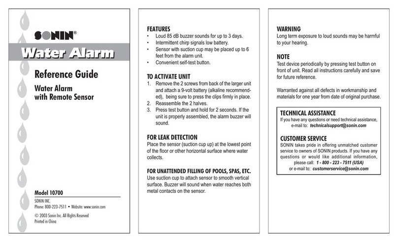
Sonin 3300 User manual

Wireless
Water Alarm
Model: 03300
Reference Guide
Detects Water and Sounds Alarm
up to 50 feet away
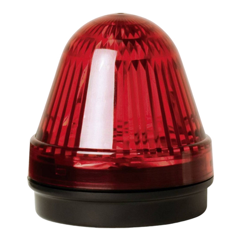
WWA-RX
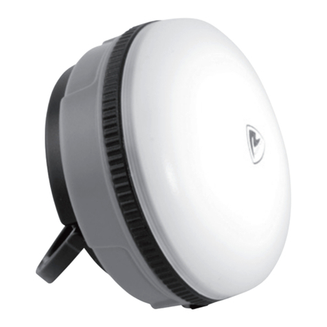
WWA-TX

Dear Customer,
Thank you very much for purchasing a SONIN Wireless Water
Alarm. To ensure proper use of this pro uct, we recommen
that you carefully rea these instructions prior to installation.
FEATURES:
§AC Adaptable and/or Battery Powered.
§Typical transmitter range up to 50 eet - Place the Receiver
where you know you'll hear it.
§Test Button - Allows you to periodically activate to ensure
unit is working.
§Low Battery Signal - Alerts you when battey needs replacing
(Transmitter only)
THIS PACKAGE INCLUDES:
§Water Alarm Receiver with holder.
§Water Alarm Transmitter with holder and Remote Sensor with
suction cup.
§UL approved AC Adapter.
§Screws and anchors.
REQUIREMENTS:
§One 9 Volt Battery (Alkaline recommended) when using the
AC Adapter.
§Two 9 Volt Batteries (Alkaline recommended) when not using
AC Adapter or as battery backup.
APPLICATIONS:
This Wireless Water Alarm is suitable or use in the Basement,
Bath Room, Kitchen, Laundry and Toilet...etc., any place you
want to detect a leak or monitor water levels.
INTRODUCTION
1

2
IMPORTANT: The Transmitter is not ater resistant. Do not
expose to ater.
INSTALL THE BATTERY
Remove the battery door rom the side o the Transmitter (WWA-
TX) see below. Attach one 9 Volt battery, being sure to press the
clips irmly in place.
INSTALL THE TRANSMITTER
Place the remote sensor (suction cup up) at the lowest point o
the loor or other horizontal sur ace where water may collect,
and mount the Transmitter at a higher point.
TRANSMITTER (WWA-RX) INSTALLATION
Gently press the slot with a
screwdriver or pen and slide
the battery door to open.
Suction Cup Sensor Contact

3
For illing pools, tubs, spas, etc. use suction cup to attach sensor
to smooth vertical sur aces. The buzzer will sound when water
reaches the two metal contacts on the sensor.
Sensor Installation
Remove suction cup and screw sensor
(contact side down) direct to the floor to
detect minimal water.
Detect water depth
around 1 mm
Using suction cup install
sensor at desired height to
monitor water levels.
Sensor ontacts
Detect water depth
around 5 mm
Sensor ontacts
Detect water depth
around 5 mm
Sensor ontacts
5 mm
10 mm
TRANSMITTER INSTALLATION (cont.)

4
Be ore mounting the Transmitter, we
recommend that you test irst to ensure
unit is properly working. Test the unit
by pushing the slide switch to "Test"
position, the alarm buzzer should sound.
To mount the bracket (Holder) o the Transmitter, drill two holes
in the desired location, then insert screws into the upper mounting
holes, letting the screw's head extend about 3mm ( 1/8" ) rom
the sur ace, then place the mounting bracket into the screw and
also tighten the upper and lower screw.
LOW BATTERY SIGNAL
The Transmitter will monitor the capacity o the Battery. I the
battery is low, the Transmitter's alarm will beep intermittently.
Replace the battery and Test unit. (The expected li e o a 9 Volt
Battery in the Transmitter is up to 1 year). Since the Receiver
may not pick up a low battery signal rom the transmitter, we
recommend that you check your Transmitter a couple o times
a year.
MOUNTING THE TRANSMITTER
84 mm (3-5/16 inch)
TRANSMITTER MOUNTING
BRA KET
TRANSMITTER SWIT H

5
IMPORTANT:
The Receiver is not ater resistant. Do not expose to ater.
INSTALL THE BATTERY
To install the battery o the receiver, slide to open the battery
door and attach one 9 Volt Battery. Replace the battery door
and turn unit on.
Since the battery li e in the
receiver is only a couple o
weeks while monitoring, it is
strongly recommended that
you use the AC Adapter and
battery back up.
RECEIVER (WWA-RX) INSTALLATION
Insert the 9V batterySlide to open the
battery door
Plug the A adapter jack
into the Receiver

6
Install the Receiver in any convenient
area where you would hear it
Place the receiver in a convenient area where you would hear
it (up to 50 eet away rom Transmitter, but make sure that it is
located within the e ective range).
TURN ON THE POWER
Plug the AC adapter jack into the Receiver, then plug into an
outlet. To turn on the Receiver slide the switch to "On" position
(located on the side o the Receiver).
TEST THE RECEIVER
To test the alarm o the Receiver, slide the Receiver switch to "Test"
position, the alarm will sound.
RESET THE RECEIVER
When the Receiver alarm sounds, you need to reset the Receiver
to stop the alarm, by sliding the receiver switch to "Reset" position,
and then back to "On" position.
NOTE: BE SURE TO TURN UNIT BACK TO "ON" FOR
CONTINUED OPERATION.
RECEIVER INSTALLATION (cont.)
Receiver Switch
WWA-RX

7
NOTE: BEFORE MOUNTING YOUR RECEIVER, TEST YOUR
RANGE.
Place the Transmitter with remote Sensor in the area needed and
place Receiver in desired location (up to 50 eet away). Turn ON
Receiver. Switch Transmitter to TEST mode. I the units are within
range, the Receiver will also sound. You can now mount your
Receiver. To start operation: Switch Transmitter to "ON" then Reset
and Switch ON the Receiver (see page 6).
WALL MOUNTING: To mount the mounting bracket (Holder)
o the Receiver, drill two holes in the desired location, ensure
hole centers align vertically, insert screws into the mounting holes,
letting the screw's head extend about 3mm ( 1/8" ) rom the
sur ace, then place the Receiver mounting bracket (holder) and
tighten the two screws. Place the Receiver into the mounting
bracket, the mounting bracket will sel -lock the Receiver.
TEST THE RANGE: BEFORE MOUNTING YOUR RECEIVER
AND/OR TRANSMITTER, TEST YOUR RANGE.
MOUNTING THE RECEIVER
RE EIVER MOUNTING
BRA KET
55 mm (2-3/16 inch)

8
1 off off off
2 off off on
3 off on off
4 on off off
5 on on off
6 on off on
7 off on on
8 on on on
Setting Switch-1 Switch-2 Switch-3
SECURITY CODE SETTING
The inter ace between the sensing unit and the receiver has a
security code to avoid alse triggering by the device which is
using the similar requency. Both transmitter unit and the receiver
are equipped with a 3 position DIP switch. Eight combinations
can be chosen. In case o a alse trigger, open the unit and
change the code setting on both units. The DIP switch setting on
both units must always be the same.
SECURITY CODE SETTING
Switch-1
Switch-2
Switch-3
Security ode Setting
for Receiver
Security ode Setting
for Transmitter

9
TRANSMITTER
Transmitter Range: Up to 50 Feet
Operating Voltage: 9 Volt battery (alkaline recommended)
Transmit Frequency: 312MHz
Code Setting: 3 position DIP switch or 8 di erent
combinations.
Sound Level: Over 80 db.
Battery Low: When battery is low, unit will beep
intermittently.
RECEIVER
Receiver Range: Up to 50 Feet
Operating Voltage: 9 Volt battery (alkaline recommended)
and AC adapter.
Receiver Frequency: 312MHz
Code Setting: 3 position DIP switch or 8 di erent
combinations.
Sound Level: Over 80 db
OTHER
Operating Temperature: 0 to 50 °C (32 °F - 122 °F)
Standard: Meets FCC Part 15 rules.
AC ADAPTOR RATING
Input Voltage: 120V AC
Output: 9V DC 300mA
SPECIFICATION

10
F NOTE: This equipment has been tested and found to
comply with the limits for a lass B digital device pursuant
to Part 15 of the F rules. These limits are designed to
provide reasonable protection against harmful interference
in a residential installation. This equipment generates, uses,
and can radiate radio frequency energy and if not installed
and used in accordance with the instructions may cause
harmful interference to radio communications. However,
there is no guarantee that interference will not occur in a
particular installation. If this equipment does cause harmful
interference to radio or television reception, which can be
determined by turning the equipment off and on, the user is
encouraged to try to correct the interference by one or more
of the following measures:
- Reorient or relocate the receiving antenna.
- Increase the separation between the equipment and
receiver.
- onnect the equipment into an outlet on a circuit different
from that to which the receiver is connected.
- onsult the dealer or an experienced radio/TV
technician for help.
FCC NOTE

SONIN INC.
2345 Route 52, Hopewell Junction, NY 12533, USA
Tel: (845) 277-4646, Fax: (845) 277-8154
Toll Free: 1-800-223-7511
Website: www.sonin.com
The Measure of Excellence R
©1999 SONIN Inc. All Rights Reserved Printed in hina
Other Sonin Security System manuals
