9
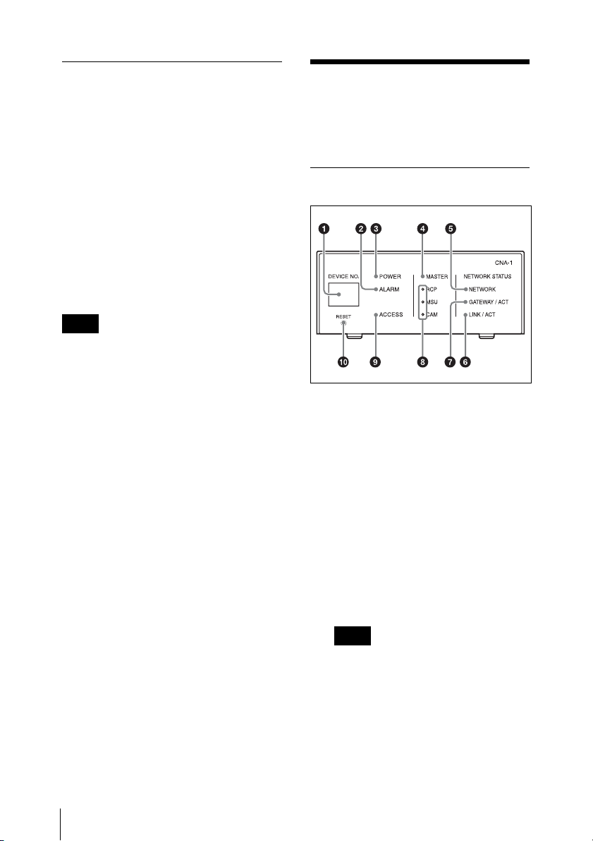
Location and function of parts
cPOWER indicator
Indicates the CNA-1’s power
status.
On: Power is being supplied.
Off: Power is not being supplied.
dMASTER indicator
Indicates the master mode status
of the CNA-1.
On: The CNA-1 is working in the
master mode.
Off: The CNA-1 is not working in
the master mode.
eNETWORK indicator
Indicates the network connection
status.
On: The CNA-1 is connected to the
network properly.
Flashing: If the CNS setting of the
CNA-1 is set to the MCS mode, the
CNA-1 is connected to the master
device properly, but there is no
destination (camera or CCU) or the
CNA-1 has failed to connect to it.
Off: If the CNA-1 is set to the MCS
mode, there is no master device or
the CNA-1 has failed to connect to
it. If the CNA-1 is set to the Bridge
mode, there is no destination
(CCU, RCP, or MSU) or the CNA-1
has failed to connect to it. If the
CNA-1 is set to legacy mode, the
CNA-1 has failed to connect to the
Gateway client device or the
CNA-1 has failed to connect to it.
fLINK / ACT indicator
Indicates the LAN communication
status of the CNA-1.
On: The CNA-1 is linked properly.
Flashing: The CNA-1 is linked
properly and data is being
exchanged.
Off: The CNA-1 is not linked.
gGATEWAY / ACT indicator
Indicates the communication status
between the Gateway client device
and the CNA-1.
On: The communication is
established.
Flashing: The communication is
established and data is being
exchanged.
Off: The communication is not
established.
hRCP, MSU, CAM indicator
Indicates the Gateway Emulation
mode status of the CNA-1. One of
the RCP, MSU, CAM indicators
turns on, or all indicators turn off.
On: The CNA-1 is working in the
Gateway Emulation mode
according to the indicator turned on
(RCP, MSU, or CAM Emulation
mode).
Off: The CNA-1 is not working in
the Gateway Emulation mode.
The MSU indicator works only if the
HZC-MSCN1 optional software is
installed. This indicator usually
does not turn on.
iACCESS indicator
Indicates the status of the internal
memory or connected USB mass
storage device.
On: The USB mass storage device
is connected.
Flashing: Read-write access is
being performed on the internal
memory or USB mass storage
device.
Off: Read-write access is not being
performed, or the USB mass
storage device is not connected.
Note