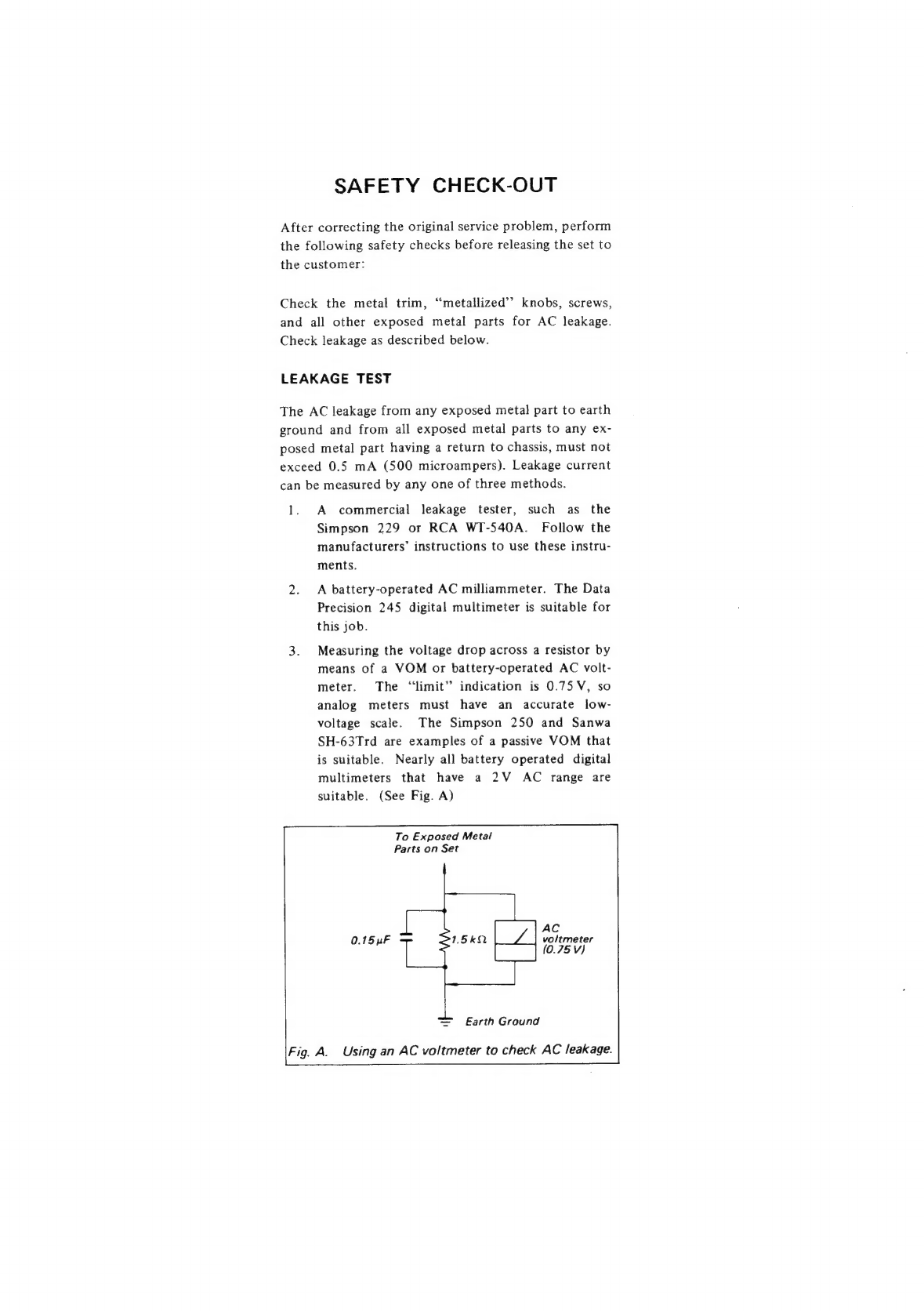
Sony CMA-10 User manual

CMA-10/10C
SPECIFICATIONS
Power
requirements
CMA-10:
120V
AC,
60
Hz
CMA-10CE:
220V/240
V
AC,
50
Hz
Power
consumption
25W
Inputs
and
outputs
VIDEO
OUT:
BNC
type
Video
0.7
Vp-p,
sync
0.3
Vp-p,
75
ohms,
unbalanced,
sync
negative
DC
OUT/VIDEO
IN:
BNC
type
DC
28V
Video
0.7
Vp-p,
sync
0.3
Vp-p,
75
ohms,
unbalanced,
sync
negative
REMOTE:
BNC
type
Serial
data
Operating
temperature
O0°C
to
+40°C
(32°F
to
104°F)
Storage
temperature
—10°C
to
+60°C
(+
14°F
to
+104°F)
Dimensions
Approx.
105
x
100
x
230
mm
(w/h/d)
(44/4
x
4
x
91/8
inches)
Weight
Approx.
2.5
kg
(5
!b
8
oz)
Accessory
supplied
AC
power
cord
(1)
ONY.
SERVICE
MANUAL

SAFETY
CHECK-OUT
After
correcting
the
original
service
problem,
perform
the
following
safety
checks
before
releasing
the
set
to
the
customer:
Check
the
metal
trim,
“metallized”?
knobs,
screws,
and
all
other
exposed
metal
parts
for
AC
leakage.
Check
leakage
as
described
below.
LEAKAGE
TEST
The
AC
leakage
from
any
exposed
meta!
part
to
earth
ground
and
from
all
exposed
metal
parts
to
any
ex-
posed
metal
part
having
a
return
to
chassis,
must
not
exceed
0.5
mA
(500
microampers).
Leakage
current
can
be
measured
by
any
one
of
three
methods.
1.
A
commercial
leakage
tester,
such
as
the
Simpson
229
or
RCA
WT-S40A.
Follow
the
manufacturers’
instructions
to
use
these
instru-
ments.
2.
A
battery-operated
AC
milliammeter.
The
Data
Precision
245
digital
multimeter
is
suitable
for
this
job.
3.
Measuring
the
voltage
drop
across
a
resistor
by
means
of
a
VOM
or
battery-operated
AC
volt-
meter.
The
“limit”
indication
is
0.75
V,
so
analog
meters
must
have
an
accurate
low-
voltage
scale.
The
Simpson
250
and
Sanwa
SH-63Trd
are
examples
of
a
passive
VOM
that
is
suitable.
Nearly
all
battery
operated
digital
multimeters
that
have
a
2V
AC
range
are
suitable.
(See
Fig.
A)
To
Exposed
Metal
Parts
on
Set
AC
0.15
uF
voltmeter
7
(0.75
V)
=
Earth
Ground
Using
an
AC
voltmeter
to
check
AC
leakage.

AFETY
RELATED
COMPONENT
WARNING
Components
identified
by
shading
and
A
marked
on
the
schematic
diagrams
and
parts
list
are
critical
to
safe
operation.
Replace
these
components
with
SONY
parts
whose
part
num-
bers
appear
as
shown
in
this
manual
or
in
supplements
pub-
lished
by
SONY.
LEAKAGE
CURRENT
MEASUREMENT
WARNING
(ONLY
FOR
USA
MODEL)
Before
returning
the
set
to
the
customer,
confirm
the
leakage
current
is
less
than
0.1mA;
1,
Between
all
exposed
metal
parts
and
any
exposed
metal
parts
having
a
return
to
chassis,
and
2.
Between
exposed
metal
and
earth
ground.

TABLE
OF
CONTENTS
1.
DESCRIPTION
OWNER'S:
RECORD
tes
coro
eict
Reiiearistieentag
eee
OUTLINE
OF
THE
UNIT
....
ee
eee
eee
eee
LOCATION
AND
FUNCTION
OF
PARTS...............
CONNECTION
EXAMPLES
......
eee
eeeeeeeee
eee
OPERATION
3.0%
tescsnestes
Sieeetdeesiey
aheate
een
ee
sent
tek.
RACK
MOUNTING
Siccrcccsas
ected
sinepieervitabsveccevaceerss
REPACKING
FOR
SHIPMENT...........c.cecceeeesenseenee
2.
ALIGNMENT
2-17
PREPARATION
iy
cecec
dieses
conesisstaawisesa
cogsaeeadacecess
2:2:
ADJUSTMENT
Siccecces
ieee
cack
eveeh
cies
aervedeaaeetviueds
2-2-1.
+48.5V
Voltage
Adjustment..................000e
2-2-2.
+9V
Voltage
Adjustment
............cccceeeee
ee ee es
2-2-3.
+5V
Voltage
Adjustment
..........ccceceeeeeeeenee
2-2-4.
—5V
Voltage
Adjustment
........
cece
ences
3.
DIARAM
Overall
Block
Diagram
................ccesecseeeeeceeeeeeees
Mounting
Diagram
2.0.0.0...
ccccecce
eee
ee
eeeee
tees
ee
eenenes
Schematic
Diagram
..........cccceceeeeeeeeeeeeeeeeeeeeeeenees
4.
SEMICONDUCTOR
.............:ccceeeeecseeeeeeereneeneeanes
5.
SPARE
PARTS
5-1.
PARTS
INFORMATION
.........
cc
ceeceseeeeeee
were
eeen
ees
5-2.
ELECTRICAL
PARTS
LIST
..........cscceceees
seen
eeeeees
5-37
EXPLODED
VIEW.
cccsccstssciasinnateatethesatesaanrentens
5-4,
PACKING
MATERIAL
AND
ACCESSORY
......ccccseccccccecnsenseeeerecea
sea
eeeas

CMA-10/10CE
SECTION
1
DESCRIPTION
This
instruction
manual
covers
two
camera
AC
adaptor
models:
the
CMA-10
and
the
CMA-10CE.
The
operating
procedures
for
the
CMA-10
and
for
the
CMA-10CE
are
the
same.
The
only
differences
between
these
models
are
their
power
requirements
and
their
connected
color
video
cameras.
120
V
AC,
60
Hz
|CMA-10CE
|
220/240
V
AC,
50
Hz
|
Power
requirements
|
Color
video
camera
to
be
connected
DXC-102
DXC-102P
OWNER’S
RECORD
The
model
and
serial
numbers
are
located
at
the
rear
of
the
unit.
Record
these
numbers
in
the
spaces
provided
below.
Refer
to
them
whenever
you
call
upon
your
Sony
dealer
regarding
this
product.
Mode!
No.
Serial
No.
The
shielded
interface
cable
recommended
in
this
manoual
must
be
used
with
this
equipment
in
order
to
comply
with
the
limits
for
a
computing
device
pursuant
to
Subpart
J
of
Part
15
of
FCC
Rules.
CMA-10/10CE
(U,CA,EK)
OUTLINE
OF
THE
UNIT
The
CMA-10/10CE
is
a
camera
AC
adaptor
designed
for
use
with
the
Sony
DXC-102/102P
color
video
camera.
@
The
power
to
the
camera
and
the
video
signal
from
the
camera
can
be
supplied
and
received
through
a
single
coaxial
cable.
e
This
unit
permits
remote
control
of
the
white
balance
and
pedestal
level
adjustments.
e@
This
unit
compensates
for
the
loss
of
the
signal
caus-
ed
by
camera
cable
extensions
up
to
300
m
(990
feet).
elt
is
possible
to
mount
four
CMA-10/10CE
units
into
a
19-inch
standard
rack.

CMA-10/10CE
LOCATION
AND
FUNCTION
OF
PARTS
Front
panel
[2]
AUTO
WHITE
BAL
button
and
indicator
POWER
switch
and
indicator
CABLE
COMP
WHITE
BAL
[>|
1
2
4
3
HUT
A,
ore
e|
i
|
|
3
]
WHITE
BAL
selector
PEDESTAL
100
«200
8)
wa
300m
id
|
4
|
PEDESTAL
level
control
[5]
CABLE
COMP
selector
(1]POWER
switch
and
indicator
Press
the
ON
side
of
this
switch
to
turn
on
the
power
to
this
unit.
The
indicator
will
light
up.
(2)AUTO
WHITE
BAL
(automatic
white
balance
adjust-
ment)
button
and
indicator
(green)
When
the
REMOTE
connector
of
this
unit
and
that
of
the
camera
are
connected,
press
this
button
to
adjust
the
white
balance
automatically.
After
the
adjust-
ment
is
completed,
the
indicator
lights
up
for
a
few
seconds.
(3)
WHITE
BAL
(balance)
selector
When
the
REMOTE
connector
of
this
unit
and
that
of
the
camera
are
connected,
the
white
balance
can
be
adjusted
with
this
selector
regardless
of
the
position
of
the
WHITE
BAL
selector
on
the
camera.
(For
details,
refer
to
“White
Balance
Adjustment”’.)
1-2
(4]PEDESTAL
level
control
When
the
REMOTE
connector
of
this
unit
and
that
of
the
camera
are
connected,
the
pedestal
level
of
the
camera
picture
can
be
adjusted
with
this
control.
(For
details,
refer
to
‘‘Pedestal
Level
Adjustment’’.)
(S|CABLE
COMP
(compensation)
selector
The
degradation
in
the
frequency
response
and
in
the
output
level
caused
by
the
camera
cable
extension
between
the
camera
and
this
unit
can
be
compen-
sated
for
by
operating
this
selector.
Select
a
selector
position
according
to
the
cable
length,
as
follows:
Cable
length
(m)
Selector
position
Less
than
100
0
About
100 100
200
200
300
300
CMA-10/10CE
(U,CA
EK)

Rear
panel
REMOTE
REMOTE
connector
==
DC
OUT
VIDEO
IN
[2]pc
OUT/VIDEO
IN
connector
[3]viDEO
OUT
connector
(4)REMOTE
connector
(BNC
type)
Connect
to
the
REMOTE
connector
of
the
camera
to
remotely
control
the
white
balance
and
the
pedestal
level
adjustments.
Notes
eWhen
this
connector
is
connected
to
the
camera,
the
camera
can
be
remotely
controlled
by
the
adaptor.
Also,
the
adaptor’s
operation
takes
priority
over
the
camera’s
operation.
elf
you
wish
to
cancel
the
white
balance
control
by
this
unit
and
to
adjust
the
white
balance
by
the
camera,
first
turn
off
this
unit,
then
disconnect
the
cable
connecting
the
REMOTE
connectors.
lf
the
cable
is
disconnected
with
this
unit
powered,
the
camera’s
white
balance
adjustment
function
will
be
inoperative.
In
this
case,
turn
off
the
POWER
switch,
and
after
a
few
seconds,
turn
it
on
again,
so
that
the
adjustment
function
will
be
operative.
(2]pc
OUT
(DC
power
output)/VIDEO
IN
(input)
connec-
tor
(BNC
type)
DC
power
is
supplied
from
this
connector
to
the
camera,
and
a
video
signal
from
the
camera
is
input
to
this
connector.
Refer
to
‘“‘Connection
Examples”
on
page
1-4.
[3]VIDEO
OUT
(output)
connector
(BNC
type)
A
video
signal
is
output
from
this
connector.
Refer
to
“Connection
Examples”
on
page
1-4.
CMA-10/10CE
(U,CA,EK)
Oi
eee
WARNING
FOR
THE
CUSTOMERS
IN
THE
UNITED
|
CMA-10/10CE
|
4
|AC
IN
receptacle
(4)
AC
IN
(AC
input)
receptacle
Connect
to
an
AC
outlet
with
the
supplied
AC
power
cord.
KINGDOM
THIS
APPARATUS
MUST
BE
EARTHED
IMPORTANT
The
wires
in
this
mains
lead
are
coloured
inaccord-
ance
with
the
following
code:
Green-and-yellow:
Earth
Biue:
Neutral
Brown:
Live
As
the
colours
of
the
wires
in
the
mains
lead
of
this
apparatus
may
not
correspond
with
the
coloured
markings
identifying
the
terminals
in
your
plug
pro-
ceed
as
follows:
The
wire
which
is
coloured
green-and-yellow
must
be
connected
to
the
terminal
in
the
plug
whichis
mark-
ed
by
the
letter
E
or
by
the
safety
earth
symto!
+
or
coloured
green
or
green-and-yellow.
The
wil
which
is
coloured
blue
must
be
connected
to
the
lerminal
which
is
marked
with
the
letter
N
or
coloured
black.
The
wire
which
is
coloured
brown
must
be
camected
to
the
terminal
which
is
marked
with
the
leter
L
or
coloured
red.
1-3

CMA-10/10CE
CONNECTION
EXAMPLES
CONNECTION
WITH
ONE
CAMERA
o*
DXC-102/102P
color
video
camera
REMOTE
|
CMA-10/10CE
REMOTE
=
DC
IN
==
DC
OUT
VIDEO
OUT
+
Cable
identification
@
+*75-ohm
coaxial
cable
3C-2V
(with
BNC
(3)
AC
power
cord
(supplied)
connectors)
This
connection
is
not
necessary
if
remote
control
of
the
Video
monitor
white
balance
and
pedestal
level
adjustments
is
not
to
an
AC
outlet
required.
@**75-ohm
coaxial
cable
5C-2V
(with
BNC
connectors)
Set
the
CABLE
COMP
selector
to
the
appropriate
position,
depending
upon
the
length
of
this
cable.
;
@75-ohm
coaxial
cable
(any
type)
(with
BNC
connectors)
to
video
input
SYSTEM
CONNECTION
USING
TWO
CAMERAS
DXC-102/102P
color
video
camera
CMA-10/10CE
Sync
generator
to
VBS
or
BS
signal
output
=:
DC
IN
=e
VIDEO
OUT
VIDEO
IN
GEN
LOCK
IN
75-ohm
coaxial
——_—
Cable
3C-2V
(with
BNC
connectors)
AC
power
cord
(supplied)
—————
to
an
AC
outlet
to
VBS
or
BS
signal
input
DXC-102/102P
color
video
to
video
output
CMA-10/10CE
to
video
input
VIDEO
OUT
GEN
LOCK
IN
;
Video
monitor
AC
power
cord
(supplied)
\
wm
to
an
AC
outlet
Le
CMA-10/10CE
(U,CA,
EK)

OPERATION
1.
Turn
on
the
POWER
switch
of
the
camera
AC
adap-
tor.
The
connected
video
camera
will
be
turned
on.
2
Turn
on
the
connected
video
equipment
(video
monitor,
VTR,
etc.).
WHITE
BALANCE
ADJUSTMENT
There
are
two
ways.
to
adjust
the
white
balance
as
described
below.
To
adjust
the
white
balance
to
the
factory-preset
values
Select
the
position
of
the
WHITE
BAL
selector
de-
pending
on
the
lighting
conditions.
Selector
position
Lighting
conditions
3200°K
(lodine
lamp,
sunrise,
sunset)
Indoors
(Fluorescent
light)
Outdoors
(Under
a
clear
sky)
For
better
color
setup
according
to
lighting
conditions
(Automatic
white
balance
adjustment)
Perform
the
procedure
described
below.
1
Set
the
WHITE
BAL
selector
to
AUTO.
2
Shoot
a
white
object
(a
white
cloth
or
a
white
wall)
with
the
camera
so
that
the
white
object
fills
the
screen.
3
Press
the
AUTO
WHITE
BAL
button.
When
the
automatic
white
balance
adjustment
is
completed,
the
indicator
lights
up
for
a
few
seconds.
The
white
balance
adjustment
function
may
not
operate
in
the
following
lighting
conditions
:
If
the
lighting
is
insufficient,
the
AUTO
WHITE
BAL
in-
dicator
will
not
light
up.
This
signifies
that
the
white
balance
cannot
be
adjusted
properly.
If
the
lighting
is
excessive,
the
AUTO
WHITE
BAL
in-
dicator
will
light
up,
even
if
the
white
balance
cannot
be
adjusted
properly.
In
this
case,
the
entire
monitor
screen
turns
greenish
to
indicate
that
the
white
balance
adjustment
cannot
be
made
properly.
In
both
cases,
try
to
adjust
the
white
balance
again
as
follows.
When
an
auto
iris
lens
is
used:
If
the
lighting
is
insufficient,
the
white
balance
cannot
be
adjusted
properly.
Increase
the
lighting
and
press
the
AUTO
WHITE
BAL
button
again.
When
a
manual
iris
lens
is
used:
lf
the
lighting
is
insufficient
or
excessive,
the
white
balance
cannot
be
adjusted
properly.
If
the
lighting
is
in-
sufficient,
open
the
iris
or
increase
the
lighting;
if
the
lighting
is
excessive,
stop
down
the
lens
iris.
Then
press
the
AUTO
WHITE
BAL
button
again.
CMA-10/10CE
(U,CA,EK)
CMA-10/10CE
PEDESTAL
LEVEL
ADJUSTMENT
The
PEDESTAL
l!evel
control
adjusts
the
pedestal
level
of
the
camera
picture.
Normally
set
this
control
to
the
center
position.
When
the
pedestal
level
adjustment
is
required,
use
a
waveform
monitor
for
best
results.
If
a
waveform
monitor
is
not
available,
display
the
color
bar
onthe
monitor
and
adjust
the
PEDESTAL
control
so
that
the
black
and
white
bars
are
black
and
white.
RACK
MOUNTING
By
using
the
RMM-1800
rack
mounting
bracket,
it
is
possible
to
install
four
CMA-10/10CE
camera
AC
adap-
tors
into
a
standard
19-inch
rack
to
create
a
well
organized
system.
REPACKING
FOR
SHIPMENT
The
repacking
procedure
is
subject
to
change.
Refer
to
the
packing
instructions
on
the
original
carton
as
well
as
those
shown
here.

|
CMA-10/10CE
SECTION
2
ALIGNMENT
2-1.
EQUIPMENT
REQUIRED
DC
Voltmeter
2-2.
ADJUSTMENT
2-2-1.
+48.5V
Voltage
Adjustment
DXC-102/102P
color
video
camera
Test
point:
CN3-1pin
Adj
point:
@RV1/PS-146
board
Spec:
+48.5+0.5Vdc
NOTE:
Be
sure
to
be
connected
to
DXC-102.
(Show
the
right)
=
DC
IN
VIDEO
OUT
2-2-2.
+9V
Voltage
Adjustment
Tast
point:
CN6-1
pin
Adj
point:
@RV2/PS-146
board
Spec:
+9.0+0.1Vdc
2-2-3.
+5V
Voltage
Adjustment
Tast
point:
CN6-7
pin
Adj
point:
@RV4/PS-146
board
:
=
DC
OUT
:
+5.0+0.
Spec
5.0+0.1Vde
VIDEO
IN
2-2-4.
—5V
Voltage
Adjustment
Tast
point:
CN6-3
pin
Adj
point:
@RV3/PS-146
board
Spec:
—5.0+0.1Vdc
,
AC
power
cord
|
(supplied)
to
an
AC
outlet
RV4
+48.5V
REG
PS-146
board
(component
side)
CMA-10/10CE
(U,CA,EK)
2-1

CMA-10/10CE
CMA-10/10CE
SECTION
3
DIAGRAM
Overall
Block
Diagram
a
an
es
ees
He
ee
>
——“‘“‘“‘“‘i‘i—i—i‘X
ee
a
ete
1c1
1/2),
Q1
1
CN:
F2
Di.
C4
0101
FRAME)
bee
tN
S\p
RECT
eae
ye
as
es
ste
©)
R38,
R39,
C28C29_
até
SER
REG
RVI
!
LPF
BUFFER
!
cNs
rere
IC1
(2/2),
2,
@3
aa
1
93, 04,
G9413
|
VIDEO
OUT
REG
OPEN
VIDEO
VIDEO
VIDEO
pETEC)
G}—+|
VIDEO
AMP
(©)
a
a2
1
as
CABLE
"
ne
ae ey
a
:
aces
pee
ACLIN
SWITCH
Q
(
4
1C2
(2/2)
—
ez
1
aie
cas
E*cowr
\
C
|
s
}
Leg
!
CABLE
COMP
SYNC
DETECT
O-200
|
SELECT
Sho
Rae
ee
'
|
Sea
|
|
CC-30
(2/2)
'
ee
102.172),
RI.
C6
bess
J
=
STARTER
a
i]
|
fg
D&DI7
Dix.cs
1C3.(172).
a4
ate
caus
RECT
+9V
TO
EACH
BOARD
92,
C15,
RG,
R7
SERUREG.
1
POWER
ON
DI
RESET
1
:
|
@-
a
11
12
{
VIDEO
SY
©
s
103
(2/2),
Q16,
Q17
1
BUFFER
F
Nate.
RESET
[2+(+)
asm
LED-49
+5V
TO
EACH
BOARD
1
1
SER
_REG
!
RVG
03
+5
105
1/2)
9
SYNC
DETECT
y
10,
a1
Di.
C18
|
1
DRIVER
CLAMP
104
4017
DI2,
Di4,
C19
QI4,
Qt
ics
1
psc
-5V
-5V_TO
EACH
BOARD
RECT
SER
REG
a12,
a13
DI,
C21
Ry
RVIO!
f
\
I
DRIVER
CLAMP
mt
nepestae
|
PS-146
;
|
a e a
a
= a
iy
=
~
1
$2
y
WHITE
BAL
|
|
|
Na
:
04
REMOTE
3
Y9>e—
{oY
purrer
(©)
WHITE
BAL
!
0G]
INV
|
|
ge
1c10
a7
1cB
[Purse
wipTH
D
|
:
ee
a
es
CMA-10
(J,
UC)
CMA-10CE
(EK)
CMA-10/10CE
(U,CA,EK)
3-1
3.2
CMA-10
(J)

CMA-10/10CE
CMA-10/10CE
Mounting
Diagram
49°4745°43
413937
3."
BSS
eS
BES
.
4
spakennebed
wD
Beem
l
HO3e,
RM
47
soarp
—SOLDERING
SIDE
—
1-620-374-11
CMA-10
CMA-10CE
PS-146
soard
“SOLDERING
SIDE
—
1-620-373-11
CMA-10
CMA-10CE
SW
=191
Board
SOLDERING
SIDE—
1-620-
378-11
CMA~10.
CMA-10CE
LE=59
oarp
SOLDERING
SIDE—
4-620-376-11
CMA-—10
CMA—10CE
LED=49
poard
CC
=30
soaro
—SOLDERING
SIDE
—
1-620-377-4114
—SOLDERING
SIDE-
cMA-10
{-620-375-11
CMA~10CE
CMA-—1C
CMA-—1OCE
3-3
3-4
CMA-10/10CE
(U,44,EK)
CMA-10
(J)

CMA-10/10CE
CMA-10/10CE
Schematic
Diagram
pp
eo
fa
eee
eens
p
Y
Q2
zsari7s
Q!
gsp774
1C1
sPcase
Q3
2scz7es
iC}
sPcase
1
48.
Sv]
SER
REG
OPEN
DETECT
|
ae
Ha
1
2
dg
|
#38
+e
ok
om
el
2
e
Sit
t
ne
Bids
2
ke
'
oe
out
hr
eal
¥ES
vioeo
aimee
we
TY
}—»-4¥———-¢-©)
NS
Ae,
a
Set
eS
a
ht
So
mt
ee
i
A
Nn
es
tes
ac
ouivioco
im
|
2
~
id
=i
Qavi:
148.59
REG
QI
asca7es
C1
axia37
Q3
2scz785
1C2
woresa65°
02
zsca7es
1C7
c4011Be
1
RM-47
soard
VIDEO
BUFFER
SYNC
SEPARATE
BUFFER
Reset
POWER
ON
RESET
iw
Q18
zsa771
Q4
rs0774
C3
sec358
1C2
nwzs030
OS
2sclz7a5
1C2
mowzv0a0
G6
2scz795
7
2sati7s
QB
2sc2785
'
New
daiwa?
sranren
UTP
A=
HFECTIn
|
oe
te
io
Rath
oats
rm
s
;
1
cw
re
eng
2
[a
[researc]
t
oer
da
.
votiea
F—
|
Pe
Prosar
eee
oe]
vr
r
‘
<
oro
[
revesta,
oxo}
he
ie
.
mt
ne
&
q
oc
wo
[m
7
‘
s
%
@)"
[~vioeo-
our
oo
fF
J
@-9
fr]
voce
we
#
j
K
[
Hove
ore
sy
[7
[—viseoin_o_}
%
eta
ee
rad
;
;
=m
3
Ct
vioeo
oor
|
o
:
a
bce
|
a
a
ere,
BTS
TE
Bit
=
s
a
ray
fsvac
@ate
aoe
LEO-49
t
oe
om
ie
1a}
19}
21]
1
12.
1
nbs
fe
Se
ee
ie
rehg
phe
BB
aod
:
:
Oat
aE
Aygo
Tab
7d
le
Bt
giay
1
1
Q10,
G12
zscz7es
14
288733
%
By
&
eee
er
Q16
2sa771
Q9
zscz7es
=I
C4
Tcs011BP
Q1t.
G13
2saivzs
QIS
2scz7es
ICS
opcase
ie
Whe.
6
-
1
17
2sati7s
1C3
srcase
soy
SHORT
DETECT
08
Naver
4
\—
-sv
sen
rea”
Tieruay
\——
osv
ser neq
——%
|
oe
|
|
|
a0
[oe
vee
€
st
Me
dy
108
+1
+
a
[sf
ake,
me
feed
ae
<hr
ae
Be
pat
aan,
=
Es
8
;
LT
felt
dea
aon
ie
‘
D
2,
©),,,
a
[7
[ert
on
so}
-
¢
nm
ct
ed
.
ai
ae
.
a
1
Orv:
vey
as
"
tts
Le}
wy
ot
dos
m
pet
if
Cd
zs
|
©)
tT
od
a
Vos
;
8
am
"*
ar
ee
a
'
RT
|
a,
na:
-s¥
as
=
a
L.
é,,
|
ao
fo
Se
ee
Ee
ee
oo
og
a
a
a
L
a
ee
ee
ea
I
WC
em
_
Oe
ea
ee
CC-30
soarp
G9,
G11
2saio0s
12
2scz7es
1
QI
2sc27es
Q2
asc27es
Q5~
OB
2sxraa
Q14
asc27a7
G3.
Q4
28c2668
QI0
2sc2608
Q13
asari7s
1
VIDEO
BUFFER
BUFFER
CABLE
COMP
BUFFER
NS
vine
output
ae
ar
is
L
She
&
Me
Z
i
an
"
vet
le
en.
Ch
©
“
Bl
oe
:
a
Q-9
7]
vibto
mo
ttf
)
c
i
.
os
a
head
e
=
u
ft
7
cme
t
S
ew
&
ol
|e
ow
&
mt
veo
out
si
Hr)
OD
He
[_vieeo
oto
[7
}-
9-9
oO
'
AC?
FF}
q)
a
vives
owt
@
[1]
©
ASB
e
ie
"
tt
|
ms
Se
Nate
:
\
Ls
ak
a
to
7
i
om
es
a
\
ad
Badets
GE
tie
SL
hk
Bat
ms
@
.
Bt
+3
o
nt
we
Sgt
Pee
ote
'
‘
ml
ga]
gst]
eRe
o
3
om
st
q
1
bash
POWER:
3-9
a
1C1
tcsoszer
mn
&
34
CABLE
COMP
SELECT
Ls
9
i
[
i}
herd
if
,
|
|
1
‘
w
o—
2
2
[er
co
a
ee
|
Ht
came
cow
La
3
ps
Pane
coe
ac
ae
|
ee
re
od
g
1
CMA-10/10CE
(U,CA,EK)
3-5
3-6
CMA-10
(J)

10/10CE
CMA-10/10CE
CMA-10/10CE
cn
oc
ov
ae
viDeo
im
Be
qur/vineg
woo
Tf
ims
Ppa
tn
Sean
pa
eee
age
eee
Bs
= - a
Ss
pS
Se
NS
Se
Ss
recente
=
fee
te
fo
SS
a
De
ovlvinco
in
@
|
2
|
- -
QI
2sc27es
1C1
px1337
Q3
2scz7es
1C2
worss3e8P
Q2
2sc27es
§C7
scao11Br
103,
1C6
tceosiBe
107
tcsor1Be
1C4
wosce20as9
ICS
tLoezce.
‘
RM-47
soard
VIDEO
BUFFER
SYNC
SEPARATE
BUFFER
neseT
POWER
OW
RESET
nv
AND
LWW.
cru
:
Da
con
COMP
'
ie
+90
abn
|
ae
bs
-
=
i
wa
v7
wv
abt
2
{77
[ripesta_wsw
out
peo
F—
|
Po
enesrac
cavern
|
a
o
fro]
revesta
ow
|
oh
Sh
a
om
mh
[veo
ote
|
on
®
oe
‘
a
eg
i
13k
ei
re
{—vineo
ova
[3
|}
—
[Trico
a}
g
i
fi
n|_
[ww Gin
Taf
er
tine
A
ks
1
{(Trineo
wt
[e+
'
«
cet
coe
Fe
fpr
t
“i
a
waeay
i
moo
f§
Ufa
oe
m2
erat
ware}
BEAT
eis
tI
wo
(ad
ono
[sfs
nao
[24]
va
at
ai
a
7
oe
nc
ma
on
a!
er
I
ma
Pst
nt
RT
a
ce
ee
Goose
ps
tg
2
cn
eas
i
CE)
oa
a
Q4
2sc2785
QS
2sc2785
1CB
secaric
Q7
asari7s
C10
1cesaepe
96
2sc2785
Durren
we,
cow
Iw
PULSE WIDTH
CON,
ta.
cm
rm:
7
pened
Ewe
[7
[sree
or)
{soa
wut
oe
|
[2
[src
our
wo]
panier
coal
any.
Ss
!
:
Ste
[-s
[ont
oat
sen}
H
Be’
‘
["s
[ot
oar
Seah]
"
ve
2
aple,
fol
tes
;
‘
|
Ps>
‘
[7
[wt
oar
se]
sero
S
7
{
1
°
y
:
r)
Plas
byod
Beat
eB
:
a
Bm
P)
:
2
wos
ow
g
Tens
[sar
ea
corte}
a
me
'
1
Pa
=
on
{1
|
wo
wi
BA
1m
oT
St
Na
Saas
as
Si
Ie
sm
a
te
ame
en
accel
a
le
ay
a
ye
a
ts
Gl
Na
i
ea
so
ae
ate
tact
an
pp
ep
Seat
gn
co
a
Set
Se
dc
a
pagel
<n
a
nl
Sete
Dolan
A
aa
eae
2802785
2841175,
FRAME
cC-30
LE-59
LED-49
PS-146
RM-47
SwW-191
CWA~10
J,
UC)
CWA-10
(EK)
3-6
3-7

SECTION
4
SEMICONDUCTOR
PIN
ASSIGNMENTS
CMA-10/10CE
The
circuit
diagram
of
IC
is
obtained
from
the
IC
data
book
published
by
the
manufacturer.
TYPE
PAGE
181555...
220000042
1LSS97
cee
cece
en
ed—2
1S2Z51..cececces
04-2
2SA1005.........4-2
2SA1048......
2204-2
2SA1115...0000004—2
2SA1169..
600000
04=2
2SALE
Dek
ee
eas
4-2
25AT
lace
ses
east
2
2ZSA933S.
eevee
eed
m2
25B7
3360
esses
weed
2
2SC1740S
...222204-2
2SC2458.
vecceee4-2
2SC2603
oe
eevee
ef-2
2SC2668.
«220000
04-2
2SC2785
2
eee
ceeee4-2
2SC2787
«oeeeceeed—2
2SD774.eeeeeee
4-2
2SK184.
2-0
eceee
04-2
BX1337..ccceeee
e473
ERA81--004...22++4-2
HD14538BP......-4-3
HD44820A69......473
NJM2903D.
eevee
4-4
RD2:7EBs.«
ss
vewse4
m2
S4VB20.
eeeeeeaeve
4-2
S4VB40.
02.
00000
04-2
CMaA-10/10CE
(U,CA,EK)
CMA-10
(J)
44
TYPE
PAGE
TC4011BP.....++24-4
TC4051BP....00004-4
TC4052BP..
2.000044
TC4069UBP.......4-4
TC4538BP...+-2004-3
TLO62CP..
20000
0
0
4-4
TLGLLSA.
.
eee
e
eee
4-2
TLG206.
cee
eeoc5ee
4-2
uPC311C.
evecce
es
44
UPC358C.
....04564-4

CMA-10/10CE
=—f_
=
181558
I
15897
a
18Z51
BOTTOM
VIEW
S4V820
ERA81-004
RD?
768
$4VB40
TLG115A
;
GREEN
ot
pF
<s
s
TLG206
:
GREEN
CATHODE
a
INDEX
Y
2841048
2SA1169
284771
2SA1005
QSAIN1S
paee
2SA1175
28A933S
iS
i
CY
||
©)
288733
25¢1740S
Ve
No:
28¢2785
280774
2sK184
2562458
BRINTED
25€2787
28C2603
25¢2668
s
4-2
CMA-10/10CE
(U,Ca
EK)
CMA-10
(J)

CMA-10/10CE
BX1337
(SONY)
SYNC
SEPARATOR
—
REAR
VIEW
—
HD44820A69
(HITACHI)
FLAT
PACKAGE
C-MOS
4-BiT
MICROPROCESSOR
HD14538
BP
(HITACHI)
—
TOP
VIEW
—
TC4538BP
(TOSHIBA)
C-MOS
DUAL
RETRIGGERABLE/NON-
RETRIGGERABLE
MONOSTABLE
MULTIVIBRATOR
—
TOP
VIEW
—
=
Voo
A
(+310418V)
1-
CR
t-
RO
1-CKp
1-CKn
OUTPUT
PULSE
WIDTH=CR
RETRIGGERABLE
M.M.V
Vo
NON-RETRIGGERABLE
M.M.V
Yoo
Voo
Voo
(+
5.0)
R6EO~RE3
RSO~RS3
R4O~R4A3
46~49
baal
oe
27'
Fy
42~45
voo
si
ale|
oS
Ryn
R33
GNO
ROM
aid
|
25
at]
tsg~a:
HLT
i]
2048
X
10
BIT
’
E57
26)
(PROGRAM
MEMORY)
pte]
Fea?
Rom
R23
TT!
128
x
10
BIT
INST,
(PATTERN
MEMORY)
DECODER]
el
|
fse~3t
Kea
Ri
RIS
[rca
sd
Gt
BIT)
EA
Rig
ROS
|
j2a~3!
Be
STACK.
REGISTER
tI.
(4x41
BIT)
GE
50,
31
Hf
|
mR
Cree,
53
7
oe
2."
rs
mas
25
ree
ag
+1}
rae
r=
4
CL?
JC)
Soy
4aT ser
4BIT
4BIT
7
vy
a
st
[sex]
@
sand
Wasit
no
n
12
4
JADDRESS-|
%
{OBIT
ING
TIME
R/
COUNTER
z
e
=
Fe
po
RAM
LF
ACL
Rte
RUPT
woxaat
|55
23
$
Osct
Fy
cesT
[age
osce
min
-o
be
2
CMA-10/10CE
(U,CA,EK)
4-3
CMA-10
(J)

CMA-10/10CE
NJM2903D
(JRC)
TC4069UBP
(TOSHIBA)
VOLTAGE
COMPARATOR
C-MOS
INVERTER
—
TOP
VIEW
— —
TOP
VIEW
—
afpev=a-d>y
Yea
Paty]
p
oft
|
Cito
|
Q,LOW
LEVEL
+
HIGH
LEVEL
TC4011
BP
{TOSHIBA}
C-MOS
2-INPUT
NAND
GATE
TLOG2CP
(TI)
=
TOP
MEW
OPERATIONAL
AMPLIFIER
(JFET
INPUT)
A
—
TOP
VIEW
—
De
iD
B
WG
=
A+B
O;LOW
LEVEL
THIGH
LEVEL
(18
to~1.5V)
TC405
1
BP
(TOSHIBA)
C-MOS
8-CHANNEL
MULTIPLEXER/OEMULTIPLEXER
—
TOP
VIEW
—
uPC311C
(NEC)
VOLTAGE
COMPARATOR
S4insouT
ft]
—
TOP
VIEW
—
S6
IN/ouT
[2]
$2
IN/OUT
SC
ouT/in
[3]
$1
IN/OUT
$7
invour
[4]
SO
IN/OUT
$5
inzour
[5]
$3
IN/OUT
EN
(ENABLE)
IN
[6]
A(
BINARY
CONTROL}
IN
Le
BIN
c
IN
uPC358C
(NEC)
DUAL
OPERATIONAL
AMPLIFIERS
—
TOP
VIEW
—
O;LOW
LEVEL
4;
HIGH
LEVEL
X:
DON’T
CARE
TC405
2
BP
(TOSHIBA)
C-MOS
4-CHANNEL
MULTIPLEXER/DEMULTIPLEXER
—
TOP
VIEW
—
YO
invout
[i]
V2
iwrour
X2
IN/OUT
YC
InsouT
X1
INsouT
Y3
IN/ouT
XC
IN/OUT
YI
INvouT
XO
IN/OUT
EN
10]
X3
IN/OUT
mo
AIN
[o}
Bin
CONTROL
oF
Vee™
;
voo
~
vee=
+3ta+
tev
LW
eT
CHANNEL
poTofof
o |
o;Low
Lever
[oT
fof
2
|
1;HIGH
Lever
[OT
1
[i
[3
|
x;ponT
care.
[i
[x]
«|
OPEN
|
4-4
CMA-10/10CE
(U,CA
,EK)
CMA-10
(J)

5-1.
CMA-10/10CE
SECTION
5
SPARE
PARTS
PARTS
INFORMATION
Safety
Related
Component
Warning
Components
identified
by
shading
marked
with
A
on
the
schematic
diagrams,
exploded
views
and
electrical
spare
parts
list
are
critical
to
safe
operation.
Replace
these
components
with
Sony
parts
whose
parts
numbers
appear
as
shown
in
this
manual
or
in
service
bulletins
and
service
manual
supplements
published
by
Sony.
Replacement
Parts
supplied
from
Sony
Parts
Center
will
sometimes
have
different
shape
and
outside
view
from
the
parts
which
actually
in
use.
This
is
due
to
‘‘accommodating
the
improved
parts
and/or
engineering
changes’
or
‘‘standardization
of
genuine
parts.’’
¢
This
manual’s
exploded
views
and
electrical
spare
parts
lists
are
indicating
the
parts
numbers
of
‘‘the
standardized
genuine
parts
at
present’’.
¢
Regarding
engineering
parts
changes
in
our
engineering
department,
refer
Sony
service
bulletins
and
service
manual
supplements.
Printed
Components
in
Bold-Face
type
on
the
exploded
views
and
electrical
spare
parts
list
are
normally
stocked
for
replacement
pur-
poses.
The
remaining
parts
are
not
normally
required
for
routine
service
work.
Orders
for
parts
not
shown
in
Bold-Face
type
will
be
pro-
cessed,
but
allow
for
additional
delivery
time.
Item
with
no
part
number
and/or
no
description
are
not
stocked
because
they
are
seldom
required
for
routine
service.
Abbreviation
DESCRIPTION
Ref.
No.
DESCRIPTION
DESCRIPTION
|
Cc
CAPACITOR
IC
IC
RESISTOR
BLOCK
CN
CONNECTOR
L
INDUCTOR
UARIABLE
RESISTOR
D
DIODE
Q
TRANSISTOR
SWITCH
FUSE
R
RESISTOR
TRANSFORMER
All
capacitors
are
in
micro
farads
unless
otherwise
specified.
All
inductors
are
in
micro
henries
unless
otherwise
specified.
All
resistors
are
in
ohms.
CMA-10/10CE
(U,CA,EK)
5-1

CMA-10/10CE
5-2.
ELECTRICAL
PARTS
LIST
CARBON
RESISTOR
(1/6W)
~
+5%,
1/6W,
non-special
type
2.22
through
IM2Q
18
.
35
}
|
Parts
No.
1-247-000-00
LZ
—
|
vaue
[Pere]
[vate
|
Parte
Vatue
[Pars
No.
12
z
362
|
796
43k.
|
870
14
ez
39
797
|
47
871
1.2
=
798
51
872
1.3
z
|
56
873
1.6
=
|
68
|
875
18
=
|
75
876
2°)
=
82
877
2.2
767
91
878
879
5-2
CMA-10/10CE
(U,(A=,EK)
This manual suits for next models
1
Table of contents
Other Sony Adapter manuals

Sony
Sony MSAC-M2 User manual

Sony
Sony DC-V700 User manual

Sony
Sony PCG-ABA1 Series User manual

Sony
Sony AC-LS1 User manual

Sony
Sony PlayStation Portable User manual

Sony
Sony ADP-MAC User manual

Sony
Sony AC-DN2B User manual

Sony
Sony IM750 User manual

Sony
Sony RHCIL User manual

Sony
Sony MSAC-FD2M - MAVICA FLOPPY ADPT WIN NT-MAC MVC-FD85 FD90... User manual