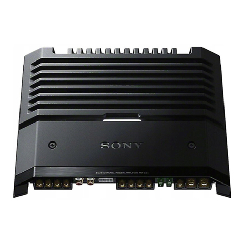
Sony TA-F45 User manual

US
Model
Canadian
Model
AEP
Model
UK
Model
INTEGRATED
STEREO
AMPLIFIER
Ju
SPECIFICATIONS
GENERAL
Power
Requirements:
120
V
ac,
60
Hz
(US,
Canadian
model)
AC
Outlets:
1
switched,
100
W
(at
max.)
220
V
ac,
50/60
Hz
(AEP
model)
(US,
Canadian
model)
2
unswitched,
total
100
W
(at
max.)
240
V
ac,
50/60
Hz
(UK
model)
Dimensions:
Aoprox.
430
(w)
x
80
(h)
x
335
(d)
mm
Power
Consumption:
90
W
(US
model)
17
(Ww)
x
3%
(h)
x
13
%
(d)
inches
140
W
(Canadian
mode!)
ncluding
projecting
parts
and
controls
220
W
(AEP
model)
Weight:
Acorox.
4.4
kg,
9
Ib
12
0z
(net)
260
W
(UK
model)
Acorox.
5.5
kg,
12
Ib
3
oz
(in
shipping
carton)
—
Continued
on
page
2
—
SAFETY-RELATED
COMPONENT
ViARNING!!
COMPONENTS
IDENTIFIED
BY
SHADING
AND
MARK
N
ON
THE
SCHEMATIC
DIAGRAMS,
EXPLODED
VIEWS
AND
IN
THE
PARTS
LIST
ARE
CRITICAL
TO
SAFE
OPERATION.
REPLACE
THESE
COMPONENTS
WITH
SONY
PARTS
WHOSE
PART
NUMBERS
APPEAR
AS
SHOWN
IN
THIS
MANUAL
OR
!N
SUPPLEMENTS
PUBLISHED
BY
SONY.
ATTENTION
AU
COMPOSANT
AYANT
RAPPORT
A
LA
SECURITE!
LES
COMPOSANTS
IDENTIFIES
PAR
UNE
TRAME
ET
UNE
MARQUE
,1\
SUR
LES
DIAGRAMMES
SCHE-
MATIQUES,
LES
VUES
EXPLOSEES
ET
LA
LISTE
DES
PIECES
SONT
CRITIQUES
POUR
LA
SECURITE
DE
FONCTIONNEMENT.
NE
REMPLACER
CES
COMPOSANTS
QUE
PAR
DES
PIECES
SONY
DONT
LES
NUMEROS
SONT
DONNES
DANS
CE
MANUEL
OU
DANS
LES
SUPPLEMENTS
PUBLIES
PAR
SONY.
AARNING!!
THIS
SET
USES
THE
SWITCHING-TYPE
POWER-SUPPLY
CIRCUIT,
WHICH
'S
DIRECTLY
CONNECTED
TO
THE
AC
POWER
LINE.
AN
ISOLATION
TRANSFORMER
SHOULD
BE
USED
BETWEEN
THE
AC
OUTLET
AND
THE
AC
PLUG
OF
THE
SET
DURING
ANY
SERVICE
TO
AVOID
POSSIBLE
SHOCK
HAZARD
WHEN
REPAIR-
ING
THE
POWER
SUPPLY
CIRCUIT.
SONY
SERVICE
MANUAL

TA-F45
AMPLIFIER
SECTION
Power
Output
and
Total
Harmonic
Distortion:
(US,
Canadian
model)
Continuous
RMS
Power
Output:
(Less
than
0.008%
THD,
both
channels
driven
simultaneously)
{AEP,
UK
mode!)
Power
Bandwidth:
(IHF)
Harmonic
Distortion:
Intermodulation
(IM)
Distortion:
(60Hz
:
7kHz
=
4:
1)
Frequency
Response:
Residual
Noise:
Dampting
Factor:
Inputs:
With
8
Q
loads,
both
channels
driven,
from
20
—
20,000
Hz;
rated
SOW
per
channel
minimum
RMS
power,
with
no
more
than
0.008
%
total
harmonic
distortion
from
250
mW
to
rated
output.
|
Maximum
S/N
_
|
input
Sensitivity:
Impedance
|
capability
|
|
(TkHz)
Setting
of
the
CARTRIDGE
LOAD
selector
(weighting
network,
-
input
Jevel)
|
90
dB
:
78dB*
(A,
2.5
mV)
At
20
—
20,000
Hz
50W
+
50W
(8
2)
According
to
DIN
45500
50
W
+
50
W
(8
2)
5
—
30,000
Hz
(AEP,
UK
model)
(A,
0.25
mV)
104
dB
78
dB*
(A,
150
mV)
Less
than
0.008
%
at
rated
output
150
mV
50
kN
Less
than
0.006
%
at
25
WY
output
Less
than
0.008
%
at
rated
output
*
"78
IHF
Less
than
0.006
%
at
25
WV
output
Measured
with
rated
output
cower
into
8-ohm
loads
(both
channels
driven
PHONO
RIAA
equalization
curve
+0.2d8
simultaneously)
at
1
kHz
TUNER
AUX
5
—
70,000
Hz
Ae
dB
Outputs:
TAPE
1,2
Less
than
130
uV
(8
2,
Network
A)
Impedance
50
(8
2,
1
kHz)
(—14.5
aB)
SPEAKER
A,B
HEAD-
PHONES
Accepts
speakers
cf
2-162
Accepts
low
ard
hich
impedance
headphones.
BASS
=
10
4B
at
100
Hz
(turnover
frequency:
500
Hz)
TREBLE
=10dB
at
25
kHz
(turnover
frequency:
5
kHz)
Tone
Controls:
Loudness:
+1008
at
100
Hz,
+3
dB
at
10
kHz
(att.
30dB)
Low
Filter:
6
dB/octave
attenuation
below
15
Hz
0dB=0.775
V
MODEL
IDENTIFICATION
Specification
Label
INTEGRATED
STEREO
AMPLIFIER
|
MODEL
NO.
TA—F45
ae
MADE
IN
JAPAN
{
aes
SERIAL
NO.
US
modei
AC
120V
60Hz
SOW
Canadian
mocel
:
AC
120V
60Hz
140W
AEP
modet
AC
220V
~50/60Hz
220W
UK
model
AC
240V
~650/60Hz
260W

1.
REPLACEMENT
OF
THE
TRANSFORMERS
IN
THE
INVERTER
CIRCUIT
The
lead
wire
arrangement
for
each
of
T901
and
T902
in
the
inverter
circuit
are
shown
in
Fig.
1.
As
the
repair
parts,
T901
and
T902
are
formed
by
only
iron
core.
Thus,
if
the
coils
are
defective,
arrange
TA-F45
2.
INVERTER
CIRCUIT
TRANSISTOR
REPLACE-
MENT
When
any
of
the
inverter
transistors
‘Qv03.
Q904)
is
broken,
replace
their
transistors
together.
A
pair
of
transistors
with
the
same
r2nk
is
provided
for
service
field.
a
new
transformers
as
shown
below.
Note
that
the
lead
lengths
must
be
exact.
Also
wind
the
coil
carefully.
_
PartNo.
|
i
X-4863-506-1
Transiszez
Ass’y,
service
Description
Q903,
904
T902
core
{1-543-100-00)
one
turn
Q
|
wire
length:
40mm
(1%
inches)
|
diameter:
0.45mm
T901
core
Erne
.
1-543-100-00.
white
i
two
turns
U
__—_
9
|
wire
length:
55mm
(2%
inches)
|
diameter:
0.45mm
(one
turn
@
|
wire
ength:
50mm
(2
inches)
\diamezer:
0.26mm
two
turns
wire
length:
70mm
(2%
inches)
siameter:
0.26mm
four
turns
,
wire
lengen:
120mm
(4%
inches)
|
diameter:
0.45mm
|
two
turns
|
wire
length:
70mm
(2%
inches)
!
diameter:
0.2mm
pulse
power
supply
board
Fig.
7

TA-F45
s
a
@
"6
2
o=
as
i
2S
~~]
(a8)
[8¥3xv3d8
|
2-W1
REESECS
t-wd
[S3NOHd
OV
3H
1-f
19348
AUVAIYd
OVLIIAO
SI
206'1060
LINDUID
BRNUL
vOv~l0v0
4
4800
v06'
1934
ONOD3S
06
‘E060
B3LU3ANI
2Ov'SOb'E0b'10b0
934
39VII0A
[
xnav
][
Manat
][ONotid
|
AR
ree
ae
oe
caer
t
9-id
$-1d
ob
-
1d
Wor
:
parce
dust
No
;
Gan
ne
sah
a
1-3d¥1
oP
(eX~
a)
°
BOL
INOR
Lo»
avo)
Hariava]
,
«
:
y
°
(ow)
-
Hi
€-1d
12
GIS
ay
@-1d
-
dav
NO
906
~
£OGO
Woo
UE
%
it
a
od
(3)
AALHO
dWW)
Cr
.
2-1-6
110
Tata
4981
o-
eens
|
+5)
dope
o--
ee
int
€0$
~10S0
favor
apaiuisv9}
o—
[ww]
7P+bS
1-4d
ONIHDLIMS
dWVI
“Te
Z-1d
~~~
NY
YIMOd
‘-
8
90r'bOr'Z0P0]
934
JOVIOA
£060
dw
3NOL
dwv
03
60b0
934
ANANHND
10vdI
ONLLAW
LIN
9419
NOILDI10Nd
JANG
Av134
60£~
90F0
Linguld
NOILIILOSd
f1€~01E0
Soe
~10£0
dW¥
YaMOd
[ssanuno7
|
t-HS
~394N0S
MOLINOW
1-1-9$
e~t
t¥<-
BWMOA
(3oN
VIVE
]
AdO09_3dvi
3NOL
ZOZAY
1O2A8
1-65
A402
Sou
1-88
140
-Ad09
3dVL
is
1
10S91
4019373S
INdNI
[_angn]
¥3040934
3dV1
xy}
=
AW——
©)
€
=
PND
[
¥3nni
]
SO)
NG
ug
Vow
08
a
1
,
~T
U0b
doe
au
f°
rf
is
Qv01
°
408!
oO
a.
+
JOdIMLaYD
od
Gore
6
€-1-GIS
avoi”
‘i
101t
3900l4L4v>
€01*
20)
‘1010
2-1-61S
———
NO
dwv
03
[_
ONOKd
T-PND
440°
wot
2-341
©)
6-1
ND
[izsaw]
—
©
7
-tN9
NOo——}-
[2-1n0
234}
Ls
gp
Lr
een
ay
Wr
©)
O1-PND
[i=1n0
938]
hyoeneal
ae
Se
ae
bP
SS
We
©)
8-tNd
NO
430°

SECTION
2
DISASSEMBLY
Note:
Follow
the
disassembly
procedure
in
the
numericai
order
given.
TOP
COVER
AND
BOTTOM
PLATE
REMOVAL
top
cover
screw
_.
top
cover
_
wy
|
ee
_
top
os
j
i
\
i
cover
screw
S
SS
i
8
;
2
y
bottom
plate
-
Sa
;
——~
PTPWH3
x
6
——-
FRONT
PANEL
REMOVAL
OBVTT3x6
A
Gi
AS
@O
knob
(VOLUME)
a
&0
BVTT3
x
6
5
TA-F45

TA-F45
Under
the
condition
shown
below,
the
circuit
boards
can
be
checked
except
for the
pulse
power
supply
board.
i
d
BVTT3x
10
audio
boar
:
y
ae
input
board
=
eres
ae
ee
omy
Ji
OVLUIL
Hari
(Uitatakakithakax
4
pulse
power
supply
case
oN
|
1)
NUINUAT
pulse
power
supply
board
|
>
_
ope
aes
speaker
output
board
(A)
LED
meter
board
we
“.
BYTT3x8
speaker
output
board
(B)
Photo
:
US,
Canadian
model
PULSE
POWER
SUPPLY
BOARD
REPAIRING
—
With
pulse
power
supply
board
grounded
—
When
checking
the
pulse
power
supply
board
out
to
connect
the
ground
pattern
of
circuit
board
with
i
of
the
pulse
power
supply
case,
use
the
two
lead
wires
pet
eed
2
roa
a
the
chassis
as
shown
below.
BVTT3
x
10
lead
wires
from
e
audio
board
g
1
of
pulse
power
supply
board
supoly
board

TA-F45
SECTION
3
ADJUSTMENTS
Note:
1.
DC
bias
and
DC
balance
adjustments
should
be
made
serveral
minutes
later
after
the
POWER
switch
is
turned
on
(POWER
ON.).
2.
Make
DC
bias
adjustment
first.
3.
Repeat
DC
bias
and
DC
balance
adjustments
two
or
three
times.
4.
After
replacing
the
power
vransistors,
DC
bias
and
DC
balance
adjustments
should
be
made.
DC
Bias
Adjustment
(With
no
signal
input)
DC
Balance
Adjustment
Procedure:
Adjust
RT301
(L-CH)
and
RTS!
(R-CH)
for
OV
readings
with
no
signal
input.
-L-CH-—
—R-CH—
Adjust
RT302
for
16mV
Adjust
RT352
for
16mV
dc
reading
on
VOM.
dc
reading
on
VOM.
Adjustment
Location:
VOM
VOM
(de
range)
{de
range)
—
R-CH
—
~—LCH—
VOM
VOM
(dc
range)
(de
range)
SPEAKER
terminals
:
:
‘A
Re
"ee
\
;
NU
Satccttl
MAMMA
SA
was
sin
ceatcaee)
aot
reteteanaie
ami
ae
wrvbiinitits
wee
ee
er
tended
ttt
eat
ON
-RT302
ahs
(L-CH)
dye
WS
DC
bias
;
ae
adjustments
|
:
:
RT352
RT301.
(R-CH)
(L-CH)
|
|
BC
dalance
|
acjustments
RT3§1
|
(R-CH)!
audio
board
Photo
:
US,
Canadian
model

TA-F45
SECTION
4
|
TA-F45
T
4-1.
DIAGRAMS
A
B
Cc
D
E
F
G
H
sea
tk
eT
BR
eo
cor
ge
|
a
ee
om
;
409
405
401
351
502
503
30!
151
iol
at
~~
=
a
A
8
406
8.70
408
eae
3h
303508
=
1
{INPUT
BOARD]
©
cuassis
EARTH
ROR
:
=
78
4
ey
4
Meh
0310
[AUDIO
BOARD)
ae
TOAD
(a.
"ay
€18°)
ANOS
S-98N-dl
TN-I
SPEAKER
A
?
CHASSIS
EARTH
ir
410)
[
out
Pur
|
PUT
K
[Lowreut]
oi
'
[SRAKee
BOARD
A
PHONO
0!
TUNER
O1
AUX
OR
PHONO
ON
QUI
VW
PHONO
ON
O.7V
€
>
Q
ee
—
:
(TUNER
ON
6.6
VY
(TUNER
ON-13v)
29
Jeli
tani
hic
i
AUX
ON
66V/
‘AUX
—
ON-I3V
J
heb)
Es
We
:
I
eo
Gam
1D
CHD
15.6
x
SPEAKER
B
[SOURCE]
a
5
=
Sm
s.
)
o
.
we
«
Seti
co
Ve
ete
I
as
.
. .
.
i
i
%
-
SON
Y
_
IP-NB8-S
|
60)
44
(1592614
3)
{SWITCH
BOARD]
1C501
‘$4
ON
$5
ON
sé
ON
S7
ON
SB ON so
ON
S10
ON
sil
ON
source]
|
i
t
OFF
|
|
(2=1]
+
i~2]
}
(Low
Fitter]
|
[Loupness]
OFF
OFF
OFF
OFF
OFF
OFF
OFF
OFF
Ic
401
TAPE
COPY
1
OFF
—=ON
2
OFF
—=
ON
3
OFF
—-
ON
[1
Note:
©
oem
>a
:
Signal
path
@
oO—
:
parts
extracted
from
the
component
side.
©
meee
meee
©
L-CH
signal
path
e
:
B
+
pattern
©
mem
semeep
©
R-CH
signal
path
—8-—
°
PEON.
8
-
pattern
©
-
:
Connect
VOM
as
illustrated
in
Fig.
1.
—9—

TA-F45
TA-F45
E
F
G
H
fete
409
405
401
35!
502
503
391
902303
1c251
«1201
ial
LY
BOARD]
©
cuassis
EARTH
[PULSE
POWER
SUPP
42V
Sis
CARTRIDGE
LOAD
DB
ra02
1.3K
(1/2w)
ah
7
(c402
0.47
0.047
h
ee
»
Ra
G54
0
P|
mma
fe
(=)
r=
a
a7Op
cs
[souce|
(TAPE
a
pelle
gs
“cli
tgs)
Ye
P-tite
z
«
!
'
:
is
pd
ot
Babin
Ab
C
0
4 as
3
.
“s
aes
was.
mara,
ud
.
1
“alo
x
oa
cet
L
“tye
J
2
5k
fh,
Larcaarery.t
9°98
at
SONY
IP
NBE-S
~~
*
x
AN
er
1
bua
Wad
:
eee
a
soo
CCS
he
cial
Rudi
:
1
592614
a
*
pv203
100KiSPeciaLh=lN.
aV204
{OOKISPECI
4_
ON
$5
ON
sé
__ON
S7_
ON
$8
ON
$9
ON
slo
on
_
SII
ON
[VOLUME
BOARD]
IRCE]
|
TAPE-2]
{
Tape-1]
ft
(OFF
]
4
(2=1]
t
[i=2]
}
{Low
Fitter]
+
[LovoNESsS|
fe
fF
OFF
OFF
OFF
oF
OFF
OFF
OFF
te)
|__
rave
cory}
mass
(1
I
SI4
Dore
|
|
AC
DETECTION
]
A)
|
peace
CNP
I
DEL
5
AC
IN
120V.
6OHz
©
mm
>
men:
Signal
path
——
©
mes
meme
©
L-CH
signal
path
©
memo
©
R-CH
signal
path
®
+
:
Connect
VOM
as
illustrated
in
Fig.
1.
—9-
|
|
|
|
|
!
|
|
|
2
m
i]
/
ne
faa
so]
S|
;
AER
UK
(220~50/60He}
iM
ODEL
UK
MODEL
-

TA-F45
TA-F45
|
A
B
C
D
E
F
G
H
4-2.
SCHEMATIC
DIAGRAM
|
|
”
7
Q101,10?
28c2545
zi
DIO!
151
1S1555
‘
1c20)
M52
141.
D30I
HZ6c2L
Q301
258646
Q302
2SA796
[INPUT
BOARD]
[tavo10
BOARD}
sina
ihisawt
alos
2SK30A
p10
~——EQAOI=138
te
0302
SV
04
Q303
25C2291
0304
P5H64B
'
ROO?
tt
Wy
IClOl
CX550
0307
1S1555
Q305
2S0668
yay
A
:
330
CLASS
A
AMP»
—————-
1
ft
|
aie
|
|
RIO3,
3311/2)
SI5-I-2
—
£0
AMP
—
ee:
i CARTR
:
[302
{
l
4
1
CNJ-1
(0)
4-4
GS
on
|
thoy
i
TRIDGE
‘oag|
—
=
ee
ee
erate
sx
=
a
4
Rode
9301
ay
:
A
~~
[PHONO
|
go!
clo)
>
4330p
if
cai
.
atk
>
ererak
iN
EI
a7
,
oT
.
2
100p
na
tsite
[iw
510
4
P08
50k
WIV
|
1.5K
any
en
CNJ-2.
(O}
aa
{
Ta
R219
C212
ey
Q30!
+
Ww
I
Quan
(
(iweuT]
[Tuner
)
=
400
|
Ria
cho
ey
%
Dk
aay]
R308
gray
t
RIOT
+
SRI08
100
33p
nf
sit-
1
wo
paw
It
antve
19k
oe"
ARais
30
56k
e
=
56k
ofr
3
1ay
AN
C
in
cow
rf
ay
wee
[Loupness|
|
w
|
iaved
ileal
{
CW-3,
(0
Wy
(
OFF
clo
as
ey
}
»
ON
;
030?
~—
AUX]
Throgs
4
aie
0.01
we
C101
|
wf
[Rue
cdo
Leos
hl
C206
iy
56OkF
ieee
t+
Ibm
+
ts)
nm
Oy
1k
0.22
=
ip
MooFr
FER
USH:
2.2/50V
oy
ov
$3K(1/2W)
CNJ-7_
G}—
eal
2°
Sey
la
a
ae
a
de
rey
Grou
yeov
|
Taste
[atte]
]
ya
A
Kay
|
if
—
[TaPe-1]
La
oy
ig
=
X7)—45
55108)
R205
«:
Rec
>)
330
|
Ik
es
ar
¥
0302
1
é
>
=
~
27
rrr
ay,
oe
ee
+
eal
Trae
a
Re
HS
(cae
ae
eg
CNJ-8_
(O}—
pen
ina
ie
———-7-—
rs
va
NV)
Saige
D101
f
ro
AFT
Pre
Geren
mae
2
REC
OUT-l]
7
5-1-3
{
-06v
Seo),
AW
15h
|
Rel?
¢209
R215
iT}
ae
”
70h
TAPE
monToR
UF
(CARTRIDGE
LOAD
Ls
|
i
aime
Lc202
wen
WT
4-139
(
RECORDER
TAPE-I
aaroe
ne
R120
I
=6018
woos
Tt
att
R30!
303
|
=
{
CN-9_
(0
ON
it
=p
570)
cays
SK
yeK
Ry204
call
233k
—
0305
few
tare)
wgniToR
Of"
Rigs
“|
ie
]
nie
fie"
iraeae]
|
SPECMY_
ime
iw
(i)
ino
TAPE-2
4
=
c=
=
=
:
2
CNu-10
(0)
ce
oN
1c
$ri04
Lrios
Lrio6
ja.2y
El
avean
linac
28206
ed
[
Bass
|
aczor]
739?
ee
yy
if
L__
[Rec
our]
7
202
aowTOR
TorF
3n
7
(00k
Fl00k
+470
100k(M)
|
250kK(R)
if
1"
R213
3
{tf
ity
ap
Ov
ia
Sey
6309
:
SOURCE
franc
ance]
|
[vouunt
|
208
ok
C210
307]
590°
=eR36
22
R307
72
R309
Pa
FD
7
IAk
“209
he
R23
0.0K2
+
220
y
220
7
39k
4a?
|e
L-cH
—
ita
5
1,645
IBV
l
aaah
Sane
ot
|
RBI
ee
‘Taronev
eed
a
anne
eee
Ee
ER
xe
eo
SR
Aenea
eee
en,
seg
ee
ee
ee
es
4
i
eee
aye
Creare
4
once
moll
3
a
;
bi
Ee
ee
[VOLUME
BOARD]
470750v
wi
R-CH
=
—
_
gio
|
i
——(¢
—
5)
a!
(ew)
te
aon
RELAY
Fa
ae
Aes
R-CH
IS
OMITTED
dane
—
=
=
1)
|
SWITCHING
yi
=
5
(REFERENCE
NO
150~I70)
“
DRIVE
|
6.
eer
[
[Tuneron
COSY
al
R-CH
IS
OMITTED
;
CW=4_
(OF
;
PHONON
Tot
oT
(REFERENCE
NO
250~260,
350~370)
CU
garememmmnaacnoe
)
caer:
-——
[PHONO
\
all3V
sh
A
RA.
3
CN-5
(0)
WM
es
cage
|
220!
TUNER
a
7
7
tr,
:
:
sown
:
Ue
and
Caen
ea
Li
;
=
[AVR
c502
|c501
|C503
Q40!
4lay
R4ll
10
A
42v
SV
1750V}1750V
|1/50V
i"
ox)
esl
fe
Seen
ee
CNJ=
IL
(O}——
=
=
Ee
SS
Se
SSeS
R427
STN
a
ea
ag
spe
ee
ae
ae
us
a
ee
Neca
eee
eee
aan
ftAPet]
Td
OM
IC40l
_Hal2002
col
i7.6V
MUTING
PROTECTION
CIRCUL
CNU-l2
(
[SWITCH
BOARD)
ee
fal
‘$i5-I-1
[REC
ouT-i]
S|.
OFF
$2.
OF
$3
=
GATOR
os
CARTRIDGE
.
2
o
|
TARE
\
‘iia
|
a
:
1s
SOURCE
or
ae
2a
ae
|
:
Serre
ee
a9
RECORDER
ON
( (
&
'
!
1904
L903
pee’
tree
ewe
PEO
ews=13,
a
Peers
et
|
LSP
gh
LTT
py
to
;
6494
|
font
Sout
0903,
904
Rie
Crare=2]
d
ae
=
ss-I'2
don
ov"
0
cTU22U
ie
al
rach
'
rig
:
[MONITOR
i
,¢420
SECONDARY
RECT
iar
TOms
ma
aaa
OE,
4
ol)
[[TaPE-2|
—
pL-a
3
F190
3I°\
Soe
(0)
CNu-I4
(
TUNER
ON
>
OR
fae
515-2-I
50V
SLT
fos
feo¥
os0a(
31
\
0.068
/
»
100K
|___
|REC
OUF2
BV)
\
(mc
] |
{J
|,
,Si5-2-
465}.
9).
EC
OUT
0508
0503
0509
ore
ARTRIOGE
brn
Mt
|
4
-
Ke
Q50!
>I
~
330
;
vs
13.8V
sas
we
ol
ssiie)!
©-24
"
psoat
‘Ipso)
PNONO
ON
__
0807
RBIs
»
[are]
[=
1800
02
R505
R506
eK
for?
238k
33k
ot
a
a
|
a
ne
3a
2200
-
50v
-32.7V
PHONO
ON
OV:
PHONO
ON
6.6V
PHONO
ON
6.6V
ATUNER
ON
6.6V)
|
LTUNER
ON_OIIV)
ATUNER
ON
66V)
——
de
AUX
ON
66V/
[AUX
ON
6.6V
J
AUX
ON
OY
R420
D501~
507
1SI555
{
i
=|
2ave
0409
9G
A
'
0508~
510
MVI2N
A
-
aay
bw}
.
:
Q501~
503
2SAI0I5
Carl.)
:
-15V
a402
-41.8V
R412
10
—42V
:
%
R510
0408
we
Q903,904
D901,902
Q902..;
ds0~
506
ae
é
~
cs
at
0401
2scl826
‘reuse
PowER
Y
1
LI
Lbomadls.
Zsczver
(esceeaa)/
“ists
2snnee
504
~
506
2SC1364
Qs
42V
fess)
TASSIS
.
-
Ten
LAMP
DRIVE
Ake
autre
WEEeA
gage
ans
aon
sete
ae
:
SUPPLY
BOARD
iM
Gaps
OT
CHASSIS
seer
C
PosycHARGins
ka
ae
IC5O\
CX770
PHONO
ON
TV
;
PHONO
ON
-1SV
PHONO
ON
-1SV
5
7E-
tf
ee
s
"
PL-4
cle
PL-5
3)
PL6
Q409
2SA76B
D408)
RD4.7E-C
Q405,407
2SC1815
Ope
INLET
SELECTOR
NNER
ON
Sy)
[PHONO]
WK
ON
ay
|
[TUNER]
ee
cha
[RUS]
mt
CURRENT
REG
Q406,408
2SAI01I5
|
e
:
Bt
bus.
EE
te
eS
Se
e
———:
B-
bus.
5
Bi
ee
eo
sis
:
Note:
e
Components
for
right
channel
have
same
values
as
for
left
e
All
resistors
are
in
ohms,
%W
unless
otherwise
noted.
e
Voltages
are
dc
with
respect
to
ground
unless
ot!
».Note:Les
composants
identifiés
par
une
trame
et
une
sa
;
SSS
See
channel.
Reference
numbers
are
coded
from
150—170,
kQ
:
10002,M2
:
1000k2
noted.
E
marque
/\\
sont
critiques
pour
la
sécurité.
Ne
les
Note:The
components
identified
by
shading
and
mark
250—260,
350—370.
e
:
Resistance
or
capacitance
value
for
AEP,
UK
e
Readings
are
taken
under
no-signal
condition
HA
:
g
:
g
remplacer
que
par
une
piéce
portant
le
numéro
are
critical
for
safety.
Replace
only
with
e
Ail
capacitors
are
in
uF
unless
otherwise
noted.
pF
:
uwuF
model.
a
VOM
(20k9/V).
spécifié.
Part
number
specified.
SOWV
or
less
are
not
indicated
except
for
electrolytics
{f}-
:
nonflammable
resistor.
no
mark
:
US,
Canadian,
AEP,
UK
model
;
sas
iiss
SS
ane
and
tantalums.
<
>
:
US,
Canadian
model
fie
a
af
Don

5S
TA-F45
TA-F45
E F
G
H
=
DIOI,
151
1S1555
7
1c201
M5214L
030!
HZ6C2L_
Q30!1
2SB646
Q302
2SA798
~
Q306,308
2SAl026
e
Q310
2SD669
A
|
plod
EQAOI-I3R
TOES
AME
0302
SV04S
—
Q303.-2SC2291
0304
258648
0307,
309
2SC1634
aaii_
2sseaa_|
|
[SPEAKER
BOARD
A‘B]
0307
ISI555
0305
250668
36
ABS
PROTECTION
CIRCUIT
4ov
CLASS
B
DRIVE
siz-1-2
[a]
'
CLASS
A
AMP
Biv
At
:
we
312
2SC2681
Bt
G502
0310
ie
313
2SAI41
or
=
LS
TM-1
ae
50v
|
Wav
8
CLASS
AMP
|
sie-t-1fal
:
[SPEAKER
A]
[sv
S10-1
R208
750k
’
i
,
me
@
FINAL
Nr
th
=e
(toe
FRTER
|
age
meee
eres
we
CD)
()
0304
Y)
sosey
40.59V,
Pe
a
1-2)
a
2.2k
22
4
Rios
Q307
=
ve
=
1
Sll-
1
sv
—ie
O56ve
SAAN)
Nig,
Sf°¥
R314
e.,
R320
OFF
2
a
oF
[Louness
gd
huoay
Mav
A100
ozov
HFG
EBSA
ve
|
ov
7}
seo!
isvet
—|ORal-
+
Ch)
rv
op
Ww
KE
wd
ai
si3-
1-18]
—
—i}—
oe
ay
Q302
a
310
0305
16mV
1ByH
on
c2or
|
Le203
R331
id
\
RACE
oY
>
ese
'
0.22
T
120p
nied
OFF
ae
ov
33k
(1/2W)
Ove
16V
|
e
|
|
TM-2
_
ed
oa
[|
a
A
Tey
T
eet
aaa
d
Sy
ia
aes
ieee
;
|
i
c3it
a2
Jf
bd
by
|
[SPEAKER
8]
3/5
"es
>
eee
:
330
|
Ik
|
¥
ose
710
a
A
1330),
PROTECT
ION
FSi
en
Bi
a
a
tee
i
:
8
mae
|
DLAI
CT
poe
|
me
eee
er
’
D101
c204
i
i
4
Ol
0306
0.33
Wt
“
y
f°
‘
:
*
W90V)
LG
Teas
|
:
360
4
0308
(aw
A\|
R3257
1.351
orr
IS
7
a
‘a
2
ivan
wr
C)
sf
gate")
fos
|
2m
{
ey
}
si2-2-1[h
;
8
"
agg
nt
ea
A
ace
ie
Gor
Ft00k
f
es
sca]
=
S3k
|
Tosos
Pye
1
|
gl
|
|
(edd
Lew’
4
R204
0.0022
neers
<
RSISA\
0.91V
0.91V
.
PIROTECTIION
R376
513
I
2/8
IM
a)
RAB
s
fe
4.7k(V/2W)
ie
:
'
'
R302
=
rh
5
av2oi_
|
Rv202
+301
;
47k
J
Ot
Marea
102
fe
1OOk(M)
|
250k(8)
T
'00p
Rai
seev")
c309
Saee7
ae
4
|
sis-2-1[8
BALANCE]
|
[VOLUME
R203
R216
i
£9307
R309
R313
150p
0303
©3304
(iw)
Re
ae
$3.9k
22
=
220
+39k
47
A
k-__}|
iw
Seas
Tet
i
|
s
!
RBIT
220
A.
HEAD
PHONES
——_—_—_
1.
—-
eee
ee
St
ty}
+--+
-—
{=
—-—
—pa——
—-——
—-
——_+—
=
{VOLUME
BOARD]
470750v
soy
D405
RDZ7E-B3z
42V
AT
ASi0"
e-
-
[anerwa
1.0.01
Toor
=
posed
t
(ew
1c401
OLTECTION
ea)
|
(a
(Ca
.
RELAY
ms
a
410
¥
151
:
me
|
SWITCHING
|
DC
DETECTION
;
aE
aay
|
100k
|
fea
ee
:
»
{ac
ber
DETECTION
mG
|
,
(REFERENCE
NO
250~260,
350~370)
i
-
We
tee
caine
D406
1S1555
|
a
nas
{
Gaon
S
va
|
|
Se
cad
1,
220k
lef
|
ea
4
:
AS
i
a
Ge
ae
-
—
Haw)
|caoe
&
pao
F
_
ae
1bV
_A
|
|
;
|
|
=
bar
I5V
0401
4iav
RAILIO
A
42V
F
;
AC300V
aaa
:
|
\
f
a
he
_
i.
&)
R427
———
HH
OO
DS
OOO
‘
See
—
;
|
$l4-2
{240v
“S018
ah
2.7k
IC401_HAl2002
D40\~
404
30DL4FA
Cais
(b
oe
UK
MODEL
MUTING
PROTECTION
CIRCUIT
<
PRIMARY
RECT
220/25V
.
GY
|
i}
Ae
0403
37.6V
Pineal
4Vp
p
i
\I
AEP
MODEL
|
PL-T
$I5-I-1
R35
Ik
0405,
R402
=
|
s
ia
os
feartRioce|
Bary
aay
2)
Ww
rao
|
;
2£
@
tt
&
330p
|
=
RAl6
22p
SIV
[
Ss
ie
=
is
[
i
|
‘
©
x
.
15k
+-IF-+—¥
—
T5047
S08
——
AEP,UK
MODEL
L
7
t
1
6.8V
0407
$300.4,
FOvH
lOwH
D903,904
:
i
SS
SS
SS
;
don
“
50V
‘|
ro
0
CTU22U
JUS,CANADIAN
ie
si
A
OR
'
6.17
Meas
SECONDARY
RECT
MODEL
|
2]
PLB
3a
i
Lican
‘]'
100
.
LPL
85Vp-p
A
|
e@
Switch
ie
|
¢
ase
Eo
®
oor
‘{09/
id
ml
g910
|
|
fee
Wor:
|
330
-
MY
fov
|
“4
Ref.
No.
Switch
Position
zt
4
ig
~0.62V
~
sel
Zi
i
©
$1
‘
ee
@)
am
a
cod,
cure
|
|
$4
PHONO
OFF
3a
v
osoa
|
$405.4,
\
S3
AUX
OFF
~
0406
oy
ae
s4
MONITOR
SOURCE
|
ON
hala
4a
377V
1]
US,
CANADIAN
S5
MONITOR
TAPE-2
OFF
Lkal/
wie
8
=
=
MODEL
y
S6
MONITOR
TAPE-1
OFF
ned
aos
(630
a
he
A
i
at
.
=
a
le
S7
TAPE
COPY
OFF
ON
a
|
oe
aaa
eee
ean
eon)
ab
“ahs
i
oe
s8
TAPE
COPY
2-1
OFF
5408
IBV
a4o2
~41.8V
Rai2
10
-42V
"4
‘pel
9903,904
D901,9
is
:
THERMAL
@
SQ
TAPE
COPY
1-+2
OFF
36.HY
Lal
0401
25c1826
[2
ULSE
POWER
)
ST
LIT
S307,
98t55
282767
(25c2240)
Prsisss
2$Ai026
ascies4
(See)
um
een
ool
re.
S10
LOW
FILTER
OFF
as
i
—
402
250768.
aa
SUPPLY
BOARD
aan
CHASSIS
INVERTER
AA
To.3y
CHARGING
—
TRIGGER
CIRCUIT
—
Se
j
j
vi
S11
LOUDNESS
OFF
——
403,404
A G
=
pe
i
;
0409
2SA768
D408
RD4.7E-C
Q405
‘407
2SC1815
50ps
$12
SPEAKERS
A
ON
CURRENT
REG
0406,408
25A1015
|
°
:
Bt
bus.
&
}
ae
asda
513
|
SPEAKERS
B
OFF
—
7
‘
.
i
ai
te
|
|
:;
UK
wiottel
$14
POWER
OFF
right
channel
have
same
values
as
for
left
e
All
resistors
are
in
ohms,
%W
unless
otherwise
noted.
e
Voltages
are
de
with
respect
to
ground
unless
otherwise
4
S15
CARTRIDGE
LOAD
32
ice
numbers
are
coded
from
150-170,
kQ
:
10002,
MQ
:
1000
k2
noted.
e
Voltage
variations
may
be
noted
due
to
normal
pro-
S16
DELAY
OFF
370.
e
[ ]
:
Resistance
or
capacitance
value
for
AEP,
UK
®
Readings
ai
Sen
under
no-signal
conditions
with
duction
tolerances.
$17
PROTECTION
ON
e
in
wF
unless
otherwise
noted.
pF
:
uF
model.
a
VOM
(20k:
e
+i:
:
Connect
VOM
as
illustrated
in
Fig.
1.
oP
Cees
re
not
indicated
except
for
electrolytics
e
ENA}
:
nonflammable
resistor.
no
mark
{
Canadian,
AEP,
UK
model
US,
Canadian
model
=
ae
~13—

TA-F45
TA-F45
~12—
A
B
C
;
D
E
F
G
H
4-2.
SCHEMATIC
DIAGRAM
°
.
Q101,102
2$¢2545
7
DIO!,
51
1S1555
.
Ic2ol
M52141.
D301
HZ6C2L
-Q301
258646
9302
2SA796
4
(INPUT
BOARD]
|
ft
[AUDIO
BOARD)
ae
ada
103
28K30A
plod
EQAOI-13R
TaN
AME
D302
Sv
04
303
25¢2291
0304
P5R648
a
‘
ROO?
‘
Ww
Iclol
Cx550
0307
1S1555
Q305
eee
‘.
ore
soy
A\220
a
[nos
330/ew)
|
sig-t-2
F
~—=
EQ
AMP
~~~
iy
as
a
--
?
[
|
Ww
[cantnuoce
toao|
:
i‘
CNJ-1
(a)
4-4
9
bo.
bar
Woy
:
-
:
a
Se
ap
ee
aa
|
ea
0301
6
AEN
R312
r-~
[PHONO]
7
190!
|
C01
i
330p
Vena
‘es
‘
z
C106
|
RS
100p
‘
tas
"470
$04
R208
750k
t
why
‘
M
ary
|
‘
ny
[Low
FILTER
|
Ww
;
CNJ-2
ae
ak
,
:
R219
C212
930!
(r)
oes
6)
{ivput}
[TUNER]
aon
ae
oN
ek?
ee
CY;
ay
nie
ar5V
Ag
:
Sue
56
OFF
a
Ww
100
ig
3
ae
eat
Kraus)
av
vik
rep
GRA
ft
Nu:3
~
OFF
‘|
J
030?
=
[ae]
ms
i
ov
_
4
t
ee
Ov:
™
>
tk
OFF
3
TAPE
COPY]OFF
(1)
wept
-
Wie
9
Ny
pM
:
CNJ-7
21
}
108
R2i7
|
R218
9
330
|
tk
:
3.3/50V
+
Hl
302
'
OFF
C102
O10!
,
3
¢307
R1302
[TARE
CO
i
10/25V
-0.1ay,
A
RI23
AV
ABD
5k
ae
om
a
—i}
-
,
47k
|
Rize
pip
R215
a
—
eet
ie
f
@
TAPE
WgNITOR
i.
_{caRTROcE
Long}
Siete
ate
vB
ash
5
S88
Ten
ree
eee
\
RECORDER
CNJ-9
ag
$70
ae
me
ite
foox
~
;
i"
Cait
3k
9395
f
{Ag+
1.
i
TAPE-2
OFF
RIOL
hte
(m1
|
WM
T
RPA
oe
pegaren
|
f
iM
bn
é
$
af
{
a.)
:
2
TARE
.
riod
Lrios
R106
olds
86
Lew
oe
CNJ-10
z
5s
,
,
a
A
L_
pecourg
Ue
pagwrton
JOFF
fs
pa
Utd
ea
i
ea
ha
a]
30
etn
ONL
kecxos
:
al
OU
|
|
R216
-Agwor
dason
R313
A
1300
Lang
oN
ok
a7
ty
=
=
Ch
==
=
560k
(/2w)
i
14,6415
15V
R3I7
220)
Seater
cene
eee
eee
Be
Ge
aes
ee
_
ony
1
Ere
cre
eee
ee
ee
Seg
ot
eee
dh:
Wes
acioac
teat
hemes
Sosy]
at
altos
soe
ERE
i)
at
ae
:
|
¢303
say
Te
We
Bee
ee
=
2
oP
tee
ye
Sipe
el
asa
say
Adah
ain
naw
Basie
stn
gates)
ice
innit
Soe
ee
ye
“Tp
470/50V
pera
«
ae
ae
pm
kane
ae
Fea
Fe
re
ane
re
as
-
oa
Sly
R408
7
[oy
eee
i
R-CH
Agi
6)
(3)
Wee
1c4ar
[os
RosT
R-CH
IS
OMITTED
pes
Dis!
Lali
oat
[swircnine
|
{ve
330
(REFERENCE
NO
(50~170)
is
-
TUNERON.Ss—=<“‘drtYS<CSCS;<;S;<CTS
oe
ap
R-CH
1S
OMITTED
a
:
‘
“LAC
cni=4_
(Q)
a
od
BVP
PHONON
eeeieee
|
(REFERENCE
NO
250~260,
350~370)
a
ie
all3Vv
3
is
R403
3
CN-5_
©
ipa
INPUT
BA
stl
'
CNI=6
|
ea
Nae!
|
iS
foros
Sara
gad
:
wee
een
R052
-9
)—@)
soz
[cso
|cs03
040!
a1av
ie
A
|
560k
Tor]
nav]
|
av
(750V|1750V
|1/50V
S
:
eee
ee
,
ae
AUX
ON
|
or
“
pe
os
Soo
ono
ia
ot
aes
=
SS
ee
dr
ee
ear
aa
ee
No
eee
ee
amis
R427
ae
|
a
A
Se
ead
eee
eee
withers
aa
Ald
Cy,
aM
1C401_HAI2002
cei
|
Ea
;
|
we
0403
37.6V
MUTING
PROTECTION
CIRCUIT
gf
CNJ-
12
&-
(SWITCH
BOARD)
i
se
=
S15-I-1
Raise
Ik
oe,
Q405
[Rec
our-i
S|
|
OFF
$2
OrF
83.
OFF
mee
BAY
ap
rd)
;
:
;
al
:
Sa
[puono]
|
S|
tuner]
|
[aux]
es
Perl
eae
229
I.6IV
FAP
i
{source},
ic
b
333,
ip
bk
ii
Y
1S
-
-
feconveR|
Gc
a
ON
ON
7
ON
|
Ly
8
ibop
g4g4
(ape-2
heen
id
saumzess
Herons
late
yee
a
a
6.8Va
1.)
9407
200.74
'
RSI7
jasv
Role
IBV
te
meal
a
my
©}
46.17V
aise
PAA
Le,
a
CN=14
(O}—
TUNER
ON
SLY
i
zt
RAIS
“dcan
Sov
Fs
0809)
p4o7]
100
R
0503
0506
=
psi0
6.8k
6.3V
.
re
ees
Ome
|
Te
jg
4
:
138
[TaPe-
|]
ii
J
=
062
>
D508
ee
R53
0505;
AUN
top
eee
~—)
R506
R501
$R507
R508)
R503
Re
6
Se
33k
"|
si
33k
33k
10k
40n
cy
3n
oul
PHONO
ON
6.6V.
PHONO
ON
6.6V.
FineR
ON
bey)
(TUNER
ON
O.IIV
_ATUNER
ON
68V)
R4I7
Mi
“Aux
ON
66V7/
“AUX
ON
6.6V"
AUX
ON
OV
420
15k
D501~
507
1SIS55
;
zeve{
9409
129
7)
1
0508~
510
MVI2N
ta
—
‘was!
aneeenBib
6.00
Q501~
503
2SAI0I5
as
A)
ai
ah
i)
jal
6596
©
“p408
ae
O42)
388
BaD
WO
ae
903,904
902
LAMP
SWITCHING
Be
oy
OVE
GG)
|
331
401
Gh
_
36.8V
401
—
FREER
Bra,
282,
(escz240)/
Pigs
ds04
~
506
25c1364
aso
NS
sos}
p
NY
Ralg
aay
eaoe
Bean
:
ee
CHARGING
=
=
Tae
oe
ci
;
:
pAo7
NZ6CAL.
A}
VOLTAGE
REG
-
ia
1C501
x70
Pugh
ON
OTY.
pL-4
PHONO
ONAN
pL~s
PHOND
ON
“IV
peg
Q409
2SA768
D408
RDA.7E-C
Q403!
aor
sis
INPUT
SELECTOR
Wh
R
oN
Ry
[PHONO|
TN
ON
ay
|
[TUNER]
AUX
ON
ov.
|
AUX
|
CURRENT
REG
Q406\408
2SAI015
|
e
Bt
bus.
7
a
=
=
rr
me
eennrenenenereemnaennenanncat
‘
eo
———:
B-
bus.
:
SSSR
Se
Note:
e
Components
for
right
channel
have
same
values
as
for
left
e@
All
resistors
are
in
ohms,
%W
unless
otherwise
noted.
e
Voltages
are
dc
with
respect
to
ground
unless
other!
p
9
g
p
ote:Les
composants
identifiés
par
une
trame
et
une
channel.
Reference
numbers
are
coded
from
150—170,
kQ
:
10002,
M2
:
1000k2
noted.
marque
/\
sont
critiques
pour
la
sécurité.
Ne
les.
.
©:
Note:The
components
identified
by
shading
and
mark
250-260,
350-370.
e
[
]:
Resistance
or
capacitance
value
for
AEP,
UK
¢
Readings
are
taken
under
no-signal
conditions
remplacer
que
par
une
piéce
portant
le
numéro
A
are
critical
for
safety.
Replace
only
with:
e
All
capacitors
are
in
uF
unless
otherwise
noted.
pF
:
uuF
model.
a
VOM
(20k2/V).
|
spécifié.
part
number
specified.
5OWV
or
less
are
not
indicated
except
for
electrolytics
©
EF}:
nonflammable
resistor.
no
mark
:
US,
Canadian,
AEP,
UK
model
|
and
tantalums.
<
>
:
US,
Canadian
model
|
4

15)
=
TA-F45
TA-F45
E
F
G
H
:
DIOI,
151
1S1555
7
Ic201
M5214L
D301
HZ6C2L
_Q301
28646
0302
2SA798
~
—~~Q306,308
25A1026
.
Q310
250669
=
;
Digs
EQAOI-13R
TONE“
AME
D302
SV
04
0303
28C2291
0304
258648
307,309
2SCI634
Q31|
258649
{SPEAKER
BOARD
A-B]
|
D307
IS1555
0305
250668
oy
oe
PROTECTION
CIRCUIT
4ov
CLASS
8
DRIVE
si2-1-2
‘4
LASS
A
AMP
AN
,
392
ae
Cae
Q3I2
252681
;
i
BS
470°
ti
0310
312
Q313
2SAII41
OFF
a
ae
50V B
CLASS
AMP
f
si2-1-1
[A]
(SPEAKER
A]
70"
FINAL
ON
heli
ete
pie
f
aa
____
R208
750k
ai
it
Oe
Rae
care
ee
re
f)
0304
;
osey!
D303~306
13-1
-2(8]
t
Rok
2p
:
$4.4y]|
R308
375)
0307
i
1S1555
an
15V
He
O56Ve
10k
R34
os
A320
ig
BR,
A
ore
ciel
l3avet
-—(ORH-
+
Ch)
TWN
Met
:
ew
L301
a,
S28)
RUT
[
er
206
0302
R331
[cao]
a
a
RY402
ay
ae
A
paee
cote
ov
ov
|
33kvew)
|
ove
i
'ev
*
;
a
[
0
1
pines
e
ea
eee
pe
Ai
ee
evr
eae
OS
ae
a
:
7
a
rAd
L
;
39198
weit
T
Reta
|
Lat
me
R322
|
me
We
im
dt,
0302
ey
hoe
(172w)
PROTECTION
anew
Fy
476’
(oer
R303
RIZ02
CD)
Ww
bt
|
WIN
gin
a2
Rize
p10!
Rae
ts
150k
=
$308
6:80
Ske
\
ow}
0306
|
|
RR
;
|
+
|
ee
al
rBe
ais
12
e209
828
soveh
11
yy
$40
pore
|,
os08
|
fama
Rey
‘asi
ae
‘
oo
7
aye
fi
56
aw
0.36
tows
‘epi
202
30;
(amy
se
|
fof
mira
Leg
;
:
ait
|
fos
(
:
!
si2-2-
Al
|
,
>
or
ees
9309
e
oN
60017
#1004
LF
16
Ton,
call
Sr.
‘si
eae
osos
fi-p
ag
|
;
a
)
Cr)
cx
L
ote
‘sel
sae
Sh
330
(SPECIAL)
|
SPP
0.0022
_—
RBIS
ogy
o.9IV
0d6a==
i?-2
GEE)
|
_(SPECIALY
Rai
piseerlion
J
Sis
218)
3
H
ai
{TREBLE}
(mss)
aus
CH)
ay)
R318
#9
;
4.7k(/2W)
a
sal
cut
01
301
330%
;
"
ch
;
aie
470p
p102
Res
100p
i
4ov
>|
RBIFSBSV")
I
cog
See
‘
aor?
MS
i
513-2-1[]
C210
R216 0307
|
500
R306
+
2R37
SR309
R313
fa
150p
0303
0304
Gpoge
zig
¢
082
$5.94
22
220 39k
47
[BI
|
aN
k-
Y
(vaw)
24k
|
bs
Jel
300
HEADPHONES
ope
r
R3I7
204
—-
a3
a
<a
i
eraser
ee
—
—
303
:
Sees
470/50V
Sey
D405
RD27E-83Z-
42V
~~
[VOLUME
BOARD]
He
cn
ee
ey
ee
Gee
arene
OB.
7]
!
Cs.
Asie"
es
Oa
_
Leow
too
I
;
Me
Ic40l
lorrecrion
(3
CS
acai
(ee
ame
>
ij
at
stave
|
[swircwne
]}
foc
evecTion
{oc
DETECTION
|
|
R10
pane
si
ia
|
k
0.7V
”
“3.2V
a
we
St
|
se.
R-CH
IS
OMITTED
po
(REFERENCE
NO
250~260,
350~370)
2
38)
2
i
406
406
151555
Wwe
C408
pRAOT
pe
ié
320k
Bh
R405
‘)
ra
tet
210k
Bes
lev
A
in
Ova
0405
Iv
040!
4tey
R4t
10
A
42V
~
hese
;
i
=
a
?
SOE
ECE
eg
a
ee
eres
427
tS
es
SO
ee
ae
a
+
—
fp
.
Be
z
i
wut
ie
Protect
a
cunt
sath
phen
30DL4FA,
Pye
0403
37.6V
ae
,
$15
-1-I
Me
0405
Ww
4p
p
ese
a2
a]
ATR
pees
C?
-)
ok
SMITOR
[a
neee
cae
Od
bs
m
wew
tt
pyaor
ale}
ass
+85
R416
22p
1.61V
5
re
io
Hk
t
hepa
Per
cane
|
|g
1903
=
Vein
nace,
tare
Oe
pees
rt
SS
p
wH
=
(Oy
=p
RSS
b
ooee
0
eR
on
-
2200
ge
he
Np
$I6
5-1-2
fon
i
(f.)
a
Sov
’
®
JNA
Tie
SV
5.2\p.p
US,
CANADIAN
:
1
aon!
t
4
6.17V
420
SeGONOHRY
RECT
LT
Hime
NY
a
amen
AAR
(5
a
ars
Ow
‘APE-2]
Pla
oe
Téa
100
Hay
S)—
801
£998
ain
alten
R903
OFF
fc
|
$i5-2-1
R4IS
‘foo
50V
(1451
0903(
|
1
100k
Fee
T
©}
9
aD
7
0404
0402
|
No.
Switch
Position
2304
:
:
:
“2
4{
fe
at
ouiror)
|
eo
cai
{1302
P
\
‘
coitts
® |
L.c4e
PHONO
OFF
|
it
16.2V
Ov
|
e
Se
\3
(1)
\
ahi
ace
i20v
6OKe
TUNER
OFF
_
3a
’
eo
rs
CSL:
0403
aa
AUX
OFF
one
eter
eo
CH
io09,
ae
eee
MONITOR
SOURCE
|
ON
a
eer
cas
Fl
T
MONITOR
TAPE-2
OFF
.
|
Pe
=
1
\
(3)
Iie
MONITOR
TAPE-1
|
OFF
ol
vaoy
v0
ae
A
EA
{
Lads
<7
pment
aceaeaa
TAPE
COPY
OFF
ON
1,
_
osu
—_
A
(aoozenctea)
oooiseee
(902
i
Rao!
336m)
F2
|
TAPE
COPY
2-~1
OFF
408
ey
aaoz
-41.8V
Ral2
(0
aey
C
903,904
901,902
ad02
:
0901
ENS
ot
“eaal
1368)
THERMAL
|
TAPE COPY
1-+2
OFF
“
NS
—_
su.8V
Sy
OECTETTS
HT
PULSE
POWER
PLT
og
BE
2sc27e7
(2sc2240)/
—_1SI555
2SA1026
2SCI634
(S2%
x
A
!
|
Cow
fiGea
See
Rar
aay
Bios
Senree
|
SUPPLY
BOARD
i
CHASSIS
INVERTER
AA
To
sy
CHARGNG
—
~
TRIGGER
CIRCUIT
—
ek
catia
UA.
44
Peerreeeree
nents
0407
HZ6C2L
Q403,404
2SK30A
}
VOLTAGE
REG
’
-_—
+
St
- -
:
~~
LOUDNESS
OFF
Q409
2SA768
0408
RD4.7E-C
4,
ae
pala
50s
.
SPEAKERS
A
ON
RRENT
:
:
ini:
A
|
:
ok
[
|:
AEP
model
SPEAKERS
B
OFF
.
; ;
'
©
antic
Mie
{
|
:UK
model,
POWER
OFF
for
right
channel
have
same
values
as
for
left
e@
All
resistors
are
in
ohms,
%W
unless
otherwise
noted.
e
Voltages
are
de
with
respect
to
ground
unless
otherwise
CARTRIDGE
LOAD
32
ywence
numbers
are
coded
from
150—170,
kQ
:
10002,
MN
:
1000k2
noted.
@
Voltage
variations
may
be
noted
due
to
normal
pro-
DELAY
OFF
)—-370.
e
[ }
:
Resistance
or
capacitance
value
for
AEP,
UK
©
Readings
aie
f:ten
under
no-signal
conditions
with
duction
tolerances.
PROTECTION
ON
are
in
»F
unless
otherwise
noted.
pF
:
uaF
model.
a
VOM
(20ks:)-
esis:
Connect
VOM
as
illustrated
in
Fig.
1.
:
All
eesti
Sh
ede
ptcepesrodhanetens
3
are
not
indicated
except
for
electrolytics
©
fae}
:
nonflammable
resistor.
nomark
=
ff,
Canadian,
AEP,
UK
model
ae
es
“
2
2
US,
Canadian
model
oa
Bs
ee

TA-F45
Replacement
Semiconductors
For
replacement,
use
semiconductors
except
in
(
).
2SA771
(2SA768)
2$C2291
M5214L
oa
fae.
Set
—~
:
“SS
Mii
on
123k
eens
2456.
ECace
1$1555
2SA798
HZ6C2L
ec
ye
RD4.7E
(RD4,7E.C)
i
"“<oy
RD27E-B2Z
(RD27E-B3Z)
i
M
é
4
canove
aCEl3
2SA1027R(2SA1026)
|
(28a1015)
28C2681
me
|
280668
‘|
:
|
2SD669A
(2SD669)
KY
{Ky
_
etter
508
if
E
|
€
(a)
e*
|
rae
288648
.
2SB649A
(2SB649)
CN
yp
eter
side
oy
a
1
¥
Cy.
q
anode
cathode
U05G
(30DL4FA)
cathode
N,
HA12002
,
A
z
SS
er
ae
i.
iMare.ng
00
+
ew:
—14—

SECTION
5
TA-F45
EXPLODED
VIEWS
B
3-703-043-21
5-1.
Label,
main
caution
(Canadian,
UK
~cceli
3-703-114-01
Note:
Label,
main
caution
(US
madei}
@
Items
marked
“6”
are
not
stocked
since
\
they
are
seldom
required
for
routine
service.
‘fei
04e
00
eh
“U49-
4-869-222-20
Some
delay
should
be
anticipated
when
Label.
cautions
Coarse
+.225.834-00
ordering
these
items.
Pa
Pesistor
100kQ.
x
2-NM/250kKQ
x
2-8,
3-703-354-11
Screw,
top
cover
unless
otherwise
noted.
(-)
=
slotted
head
<
67-603-046-00
Printed
Circuit
Board.
Speaker
switch
[Ab
variable;
BALANCE
VOLUME
“RV201,
202, 251,
252)
S
e
All
screws
are
Phillips
(cross
recess)
type
1-507-669-00
Jack,
HEADPHONES
(/1)
3-703-354-11
61-603-047-00
.
Screw,
top
cover
Printed
Circuit
Board,
speaker
/
switch
(B}
:
1-§53-303-00
_
Switch,
rotary
slide;
4
, ;
CARTRIDGE
LOAD
1.§53-319-00
(US,
Canadian
model)
(S14)
1-553-167-00
.
(S15)
1-553-447-00
(AEP,
UK
model}
(S14-1
—
2)
Switch,
pushbutton;
SPEAKERS
A,
8
g
ji
hy
5
($12,
13)
Switch,
pus
button;
POWER
S12,
4
1-603.045-00
a
X-4866-602-0
.
Printed
Circuit
Zoarc.
voiume
Knob
Ass‘y,
ey)
es
4-848-642-00
ms
NG
Cushion,
vibration
$7-603-049-00
3-553-224-00
Printed
Circuit
Board,
switch
Cushion
4-866-322.11
1-552-539-00
Knob,
POWER
Switch,
keyboard;
PHONO,
TUNER,
AUX
‘S1-
3)
oe
Ss
\
8)
Supplied
ST
ry
volume
control
fy
mn
oe
¢
1.6
18-409-21
:
L
i
ae
3-831-441-XK
eo
pi
,
=
amp,
pilot
8VtOmA
(P11
—
5)
Supplied
with
jack
Spacer,
«noo
4-812-134-00
a
UPPED
WIEN
IBCK
4
366.602.00
Rivet,
plastic:
3.50
S
Bracket,
switch
:
V
SA
64-869-211-00
Bracket,
lamp
3-558-406.00
(Canadian
model)
9-911-845-XX
7558-406-11
(US,
AEP,
UK
model)
4-866-622-00
3-701-690.00
rain
.
nod
'D),
CARTRIDGE
LOAD
Label,
MADE
INJAPAN
“OS710P
S
ais
Holder
tame
Ws
ee
(UK
model}
«8
as
.
sn
4-866-652-00
BNLISES
?
Spring,
compression
4-866-604-00
~
Joint,
pushbutton
\
4-869-230-00
ee
compression
<“€
/
64-866-634.00
Stopper,
soring
aA
4-866-603-00
Sen
=
MSD,
wa
Pushbutton;
SPEAKERS
A,
8,
SOQ
ey
=
pesos
LOUONESS,
LOW
FILTER
SS
:
-.
cw,
A
LK.
.,
pring,
compression
.
&
a)
A
A
dG69
204-1
ieee
S
Sea
gOS
4-866-6
16.00
.
\_?
late,
indication;
monitor
Pushbutton
Ass‘y,
LOUDNESS,
>
'
|
\.
ec’
eA
r
;
a
oe
\
9.911-829-XxX
4-866-626.00
|
X-4869-205.
LOW
FILTER,
SPEAKERS
A,
8
including
parts
marked’
A+u
A,B
{
f
i
|
Knob
Ass’y,
fONITOR
W6
4-866-603-00
|
Cushion
:
Zi
Knob,
MONITOR
!
° :
g
!
S
Pushbutton;
TAPE
COPY
|
“
A
j
CMNING
ars
sated
8A!
>
4-866-617-00
X-4869-202-0
|
eo
x
Knob
Ass’y,
BALANCE
eee
7
Indication,
‘unction
,
X-4869-203-1
X-4869-201-0
Knob
Ass’y,
function
Knob
Ass’y,
VOLUME
including
part
marked
DA
X-4869-207-1
|
fs
x-4869.206-1
|
Panel
Ass’y,
front
i
|
Pushbutton
Ass‘y,
TAPE
COPY
'
|
including
parts
marked
&
A.
BA,@A\
;
including
parts
markeda
A
-C
i
Note:
Les
composants
identifiés
par
une
trame
it
une
marque
A
sont
critiques
pour
la
sécurité.
Ne
les
remplacer
que
par
une
piéce
portant
Je
nu-méro
spécifié.
Note:
The
components
identified
by
shading
and
mark
are
critical
for
safety.
Replace
only
with
part
number
specified.

TA-F45
P3x8
Serrated
Toothed-head
Screw
BVTT3x6
A
1-534-817-XX
(AEP
model]
§4-835-639-00
1-534-986-XX
(US,
Canadian
model)
Plate,
ground
:
4-857-425-50
1-551-884-00
(UK
model}
Sects.
PTTWH3
x
6
Bushing,
‘-suiation
Cord,
power
(CNPT)
PTTWH3
x
6
>i
1
meee
SZ,
Py
ze
3-701-682-00
Se
|
4.869-204.00
(US
model)
(US,
Canadian
model)
>
4-869-205-00
(Canadian
model)
Stopper,
cord;
HIF!
Z
4-869-206-00
(UK
model)
3-703-244-00
Label,
spec:tication
'
Bush,
cord
(AEP,
UK
mode/)
BVTT3
x
10
‘
4-869-217-00
Lug
y
Clip,
cord
.
Y
Pulse
power
supply
section
wh
4-869-201-00
‘AEP,
UK
model)
1-526-574-00
(See
page
17.)
ee)
4-869-202-00
‘US,
Canadian
model)
Socket,
3P,
AC
OUTLET
BVTT3
x8
|
Plate,
jack
(US,
Canadian
mocel)
(CN1)
4-809-246-00
Label,
AC
120V,
60Hz
(US,
Canadian
model)
ya
ee
|
-507-700-
“Tg
Spacer,
terminal
|
feck
pia?
3-706.
165-00
Lug
'
1-536-571-00
:
4P
Terminal
Board
(TMT,
2)
:
\
3-703-044-24
H
Label,
caution
({CNJ7
—
14:
‘US,
Canadian
model}
Screw
|
@4-856-637-00
!
BVTT3x6
~_
1-507-751-00
|
Chassis
as
;
;
Jack,
pis
BP
(CNJT
—
6)
|
eS
a
Re
\
|
Es
41-603-048-00
eS
a
\
Printed
Circuit
Board,
input
BVTTS
RS
(hos
@
BVIT3
x6
te
3-701-191-99
,
|
Foot
Ass‘y,
mini
=
ug
BVTT3x6
BVTT3
x8
QO
8310
Ke)
Foot
Ass’y,
MF
BVTT3
x6
i
2
i
&
a
$4-266-638-00
&
0
Chassis
(R)
BVTT3X6
4.579.409.11
,
Lamp,
pilot
8V
40mA
(PL7,
8)
4-866-622-00
Holder,
lamp
9-911-863-XX
Plate,
insulation
Z
a
&
BVTT3x6
cD
X-4861-312-0
;
}
=
Foot
Ass’y
64-869-220-00
2
Panel,
sub
&
Z
BVTT3x6
BVTT3x6
BVTT3x8
3-703-081-21
Label,
sub-caution;
side
(US
model)
Note:
Les
composants
identifiés
par
une
trame
et
une
marque
A
sont
critiques
pour
la
sécurité.
Ne
les
remplacer
que
par
une
piéce
portant
le
numéro
spécifié.
Note:
The
components
identified
by
shading
and
mark
|
A
are
critical
for
safety.
Replace
only
with
;
part
number
specified.
:
—16—

64-862-237-00
Bracket,
inverter
transistor
retainer
4-863-511-00
Retainer,
inverter
transistor
61-600-663-00
Printed
Circuit
Board,
pulse
power
supply
4-863-512-00
Rubber,
insulation;
inverter
transistor
$4-863-509-00
Heat
Sink,
inverter
transistor
4-863-515-00
Sheet
‘C},
insulation
(AEP,
UK
model)
4-86
1-040-00
red
Label,
pulse
power
supply
indication,
64-863-508-00
Bracket,
transistor
|
64-863-540-00
(US,
Canadian
model)
4-863-549-00
(AEP,
JK
model)
Plate
(B),
shieid
}
/
6
4-863-539-00
(US,
Canadian
model)
4-863-548-00
(AEP,
UK
mocel)
Plate
(Aj,
shield
L
-
|
4-863-5
13-00
(US,
Canadian
model)
4-863-5
14-00
(AEP,
UK
model)
Sheet
(8),
insulation
—17—
4
4-863-5
16-00
Case,
pulse
power
surciy
4-863-552-00
Case,
plastic;
inszfation
(AEP,
UK
mocei:
64-863-539-00
(US,
Canadian
mode!)
4-863-548-00
(AEP,
iX
model)
Plate
(A},
shield
64-863-540-00
(US,
Canadian
mode!)
4-863-549-00
(AEP.
-/K
model)
Plate
(B),
shield
64-863-5
10-00
Holder,
sulse
powersupply
board
q
BVIT3x
12
eae
BVTT
3x6
&
Sy
BVIT3
64-863-577-20
Lid,
puise
cower
suppY

\
™~
im
as
3-701-948-18
Label,
indication,
fuse
capacity
(AEP,
UK
model)
1-532-272-XX
(US,
Canadian
model)
\
Fuse,
5A
(F
1}
1-532-286-00
(AEP,
UK
model)
Fuse,
2.5AT
(F1)
\
1-517-072-00
(US,
Canadian
model)
1-533-131-00
(AEP,
UK
model}
Fuse
Holder
64-855-604-00
Stopper,
capacitor
\
1-§32-556.
4
64-866-655-00
Plate,
shield
1-226-262-00
Resistor,
variable;
100k:
100k
2
-special
BASS
({P'/204,
254)
1-226-267-00
Resistor,
variable;
100k
2
/100k
2.
special
TREBLE
‘RV203,
253)
44-866-080-00
Heat
Sink
1-553-302-00
Switch,
pushbutton;
LOUONESS,
LOW
FILTER.
TAPE
COPY
(S7
—
11)
1-553-170-00
Switch,
pushbutton;
+
SOURCE,
TAPE-},
~4PE.2
'S4,
5,
6)
Note:
The
components
identified
by
shading
and
mark
Note:
AA
are
critical
for
safety.
Replace
only
with
part
number
specified.
-18—
Fuse,
2A
(F2)
oie
oOo
ss
6
4-866-655-00
Plate,
shield
(US,
Canadian
moce
BVTT3
x8
ee
9.317-863-XX
Plate,
insulation
(A)
4-863-52°-00
Sheet,
insulation
/
Relay
(RY401)
1-515-347-00
/
Relay
(RY402)
eb
F-266-553-00
near
Sink
(O}
-266-547-00
4a3¢
Sing
3-504-00
,
slide;
CARTRIDGE
S15)
64.866-654.00
leat
Sink
(S)
1-603-044-00
Printed
Circuit
Boarc.
3u2°>
\.9-911-852-XX
Cushion
Les
composants
identifiés
par
une
trame
et
une
marque
A
sont
critiques
pour
la
sécurite.
Ne
les
remplacer
que
par
une
piéce
portant
le
numéro
spécifié.

Ref.
No.
Part
No.
Description
SEMICONDUCTORS
Transistors
Q101,
151
-729-354-52
2S8C2
Q102,
152
8
354-5
$C2545
Q103,153
8-729-203-04
2SK30A
Q301,351
8-729-304462
2SB646A
Q302,352
8-729-679-82
2SA798
Q303,
353
8-729-629-12
2SC2291
Q304,
354
8-729-364-81
2SB648
Q305,355
8-729-366-81
2SD668
Q306,
356
8-729-612-77
2SA1027R
Q307,357
8-729-663-47
2SC1364
Q308,
358
8-729-612-77
2SA1027R
Q309,
359
8-729-663-47
2SC1364
Q310,
360
8-729-306-92
2SD669A
Q311,361
8-729-304-92
2SB649A
Q312,
362
8-729-168-11
2SC2681
Q313,363
8-729-114-11
2SA1141
Q401
8-729-308-62
2S8C1986
Q402
8-729-377-12
2SA771
Q403,
404
8-729-203-04
2SK30A
Q405
8-729-66347
2SC1364
Q406
8-729-612-77
2SA1027R
Q407
8-729-663-47
2SC1364
Q408
8-729-612-77
2SA1027R
Q409
8-729-377-12.
2SA771
Q501~—503
8-729-612-77.
2SA1027R
Q504—-506
8-729-663-47
2S8C1364
Q901
A\8-129-663-47
28C1364
Q902
A\8-729-612-77
2SA1027R
2903,
904
A\X-4863-506-1
Transistor
Ass’y,
service
2S8C2767
x
2
ICs
1C101,151
8-759-305-50
CX550
1C201,
251
8-759-652-14
M5214L
IC401
8-759-320-02
HA12002
IC501
8-759-700-00
CX770
SECTION
6
ELECTRICAL
PARTS
LIST
e
Items
marked
“6
are
not
stocked
since
they
are
seldom
required
for
routine
service.
Some
delay
should
be
anti-
cipated
when
ordering
these
items.
Note:
The
components
identified
by
shading
and
mark
A\
are
.critical
for
safety.
Replace
only
with
part
number
specified.
TA-F45
Ref.
No.
Part
No.
Description
Diodes
D101,
151
-
8-719-815-55
181555
D102,
152
8-719-931-13
EQBO1-13
D301,
351
8-719-910-68
HZ6C2L
D302,
352
8-719-300-11
SVO04S
D303,
353
2
2);
8-719-815-55
181555
D307,
357
|
D401-404
A\8-719-911-55
U0SG
D405
8-719-127-25
RD27E-B2Z
D406
8-719-815-55
181555
D407
8-719-910-68
HZ6C2L
D408
8-719-147-77
RD4.7E
DS01-507
8-719-815-55
181555
D508-510
8-719-912-00
MV12N
D901,
902
A\8-719-815-55
181555
D903,
904
A\g-719-300-22
CTU22U
CAPACITORS
All
capacitors
are
in
uF
unless
otherwise
noted.
SOWV
or
less
are
not
indicated
except
for
electrolytics
and
tantalums.
pF
:
uuF
C401
A\1-130-197-00
C401,
417
A\1-161-734-00
C402.
=
AA1-130-234-00
c402
~=—s-_
A\1-130-342-00
C403.
A\1-125-222-00
C403
A\1-125-223-00
C901,
909
A\1-130-141-00
C902,
903
A\l-161-516-00
C902,
903
esta
si
;)A\1-161-734-00
0.0022
125V
ceramic
(US,
Canadian
model)
0.0022
400V
crarnic
(AEP,
UK
model)
0.047
125V
film
(US,
Canadian
model}
0.47
300V
film
(AEP,
UK
model)
330
400V
(AEP,
UK
model)
1000
200V
eectxolytic
(US,
Canadian
modef)
eectrolytic
0.01
630V_—
film
0.001
125V
crarnic
(US,
Canadian
model)
0.0022
400V
crarmic
(AEP,
UK
model)
=
Note:
Les
composants
identifiés
par
une
tram:
et
une
marque
A
sont
critiques
pour
la
sécurité
Nye
les
remplacer
que
par
une
piéce
portant
le
»urméro
spécifié.

TA-F45
Ref.
No.
Part
No.
Description
Ref.
No.
Part
No.
Description
C904
A\1-123-290-00
10
400V
__
electrolytic
R902
A\-247-141-00
2.7k
%W
carbon
(AEP,
UK
model)
!
(nonflammable)
C904
AN1-123-565-00
33
200V
_
electrolytic
|
R903
A\1-244-521-15
100k
YW
carbon
(US,
Canadian
model)
(US,
Canadian
model)
C905
A\1-108-246-00
.
0.047.
50V
mylar
:
R903
A\1-244-929-00
220k
YW
carbon
C907,
908
A\1-130-356-00
0.47
250V
_—s
film
(AEP,
UK
model)
(AEP,
UK
model)
R904
A\1-246-507-15
27k
“WwW
carbon
C907,
908
A\l-130-357-00
1
250V
ss
film
R905
A\1-246-469-15
680
YW
carbon
(US,
Canadian
model)
€910--913
A\1-123-361-00
220
50V
_
electrolytic
|
R906
~—
AN1-244-821-00
6.8
%W
carbon
:
(US,
Canadian
model)
RESISTORS
R906
=
A\1-244-822-00
7.5
Ww
carbon
,
.
.
;
(AEP,
UK
model)
All
resistors
are
in
ohms.
Common
%4W
carbon
resistors
are
omitted.
Refer
to
the
list
on
the
last
page
for
their
part
numbers.
H
RT301,351
1-226-232-00
_
$00-B,
adjustable;
de
barance
k2Q
:
10002,
MQ
:
1000k2
R312,
362
Raina
7
)ANI-247-099-00
R314,
364
RIS.
36
-)Ay-247-107-00
R316,
366
9517.
46
DAN-247-115-00
R322,
372
A\l-247-288-00
R323,
373
ca
pAy217-152-11
R327,
377
A\l-213-139-00
R401
—
AAI-205-598-00
R401
—
ANI-205-599-00
R405
—
AN-206-6
70-00
R408
=
A\l-247-239-00
R411,
412
ANI-247-083-00
RS15
R901
A\1-246-483-15
A\\-247-107-00
47
100
220
330
0.33
470
33
YW
YW
YW
“WwW
2W
1W
SW
carbon
(nonflammable)
carbon
(nonflammable)
carbon
{nonflammable)
carbon
(nonflammable)
wirewound
metal
oxide
(nonflammable)
wirewound
(US,
Canadian
model)
15
(AEP,
UK
model)
1.8k
“910
10
100
2.7k
SW
2w
YAW
AW.
yw
“YW
wirewound
metal
oxide
(nonflammable)
carbon
(nonflammable)
carbon
(nonflammable)
carbon
(nonflammable)
carbon
RT302,352
1-226-235-00
RV201,251
-226-834-00
RV202,252)
1226-834-0
RV203,
253.
1-226-267-00
RV204,
254
1-226-268-00
5k-B,
adjustable;
dc
bias
100kx2-NM/250kx2-B.
variable;
BALANCE,
VOLUME
100k/100k-special.
variable;
TREBLE
100k/100k-special.
variable;
BASS
MISCELLANEOUS
|
NI
A\1-526-574-00
/
CNJ1-6
—-1-507-701-00
|
CNJ7-14
—_-1-507-700-00
:
CNP1
=
A\1-534-817-XX
CNP1
—A\1-534-986-XX
|
CNPL
=
A\1-551-884-00
|
Fl
A\1-532-272-XX
i
Fi
A\1-532-286-00
|
F2
A\i-532-556-00
/
SO
1-507-669-00
L001,051
1-407-519-00
$1301,
351
—
1-420-872-00
L901
A\i-421-328-11
L901
A\i-421-340-00
Note:
The
components
identified
by
shading
and
mark
-
A\
are
critical
for
safety.
Replace
oniy
with
—
part
number
specified.
—20-—
1902-906
A\1-421-329-00
PLi-6
1-518-409-21
AC-outlet,
3P
(US,
Canadian
model)
Jack,
pin
6P
INPUT
Jack,
pin
4?
TAPE
RECORDER
Cord,
power
(AEP
model)
Cord,
power
(US,
Canadian
model)
Cord,
power
(UK
model)
Fuse,
5A
(US,
Canadian
model)
Fuse,
2.5AT
(AEP,
UK
model)
Fuse,
147°C
2A
Jack,
HEADPHONES
Microinductor,
8uH
Coil,
air-core
1.8uH
Coil,
choke
(Line
Filter)
(US,
Canadian
model)
Coil,
choke
(Line
Filter)
.
(AEP,
UK
model)
Coil,
choke
10uH
Lamp,
pilot
8V
40mA
Note:
Les
composants
identifiés
par
une
trame
et
une
marque
A\sont
critiques
pour
fa
sécurité.
Ne
les
remplacer
que
par
une
piéce
portant
le
numéro
spécifié.
Table of contents
Other Sony Amplifier manuals

Sony
Sony TA-F590ES User manual

Sony
Sony TA-AV661 User manual

Sony
Sony XM-1252GTR - Power Stereo Amplifier User manual

Sony
Sony TA-FE600R User manual

Sony
Sony XM554ZR - XM Amplifier User manual

Sony
Sony TA-VE215 User manual

Sony
Sony TA-AV411 User manual

Sony
Sony TA-N80ES User manual

Sony
Sony TA-WR4 User manual

Sony
Sony TA-FA777ES User manual

Sony
Sony XM-2200GTX Operating & Mounting User manual

Sony
Sony TA-VE110 User manual

Sony
Sony TA-FA777ES User manual

Sony
Sony XM-ZR602 User manual
Sony
Sony xm-423sl User manual

Sony
Sony EXM-202 User manual

Sony
Sony XM-2200GTX Operating & Mounting User manual

Sony
Sony TA-AX310 User manual

Sony
Sony 4-151-113-11 (1) User manual

Sony
Sony TA-F3000 User manual