manuals.online logo
Brands
  1. Home
  2. •
  3. Brands
  4. •
  5. Sony
  6. •
  7. Amplifier
  8. •
  9. Sony TA-N80ES User manual

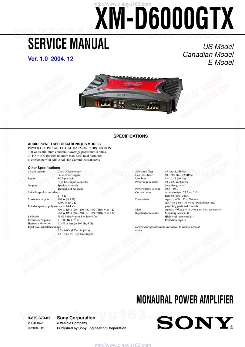
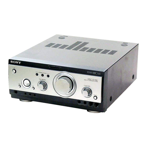
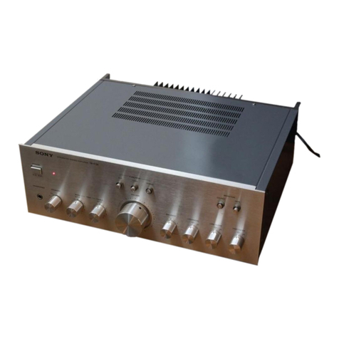
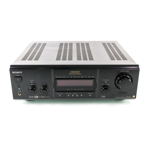
Sony TA-N80ES User manual

SERI|IGE
MANIJAL AEP Model
E Model
SPECIFICATIONS
AUDIO
POWER
SPECIFICATIONS
POWER
OUTPUT
AND
TOTAL
HARMONIC
DISTORTION:
With
4ohm
loads,
both
channels
driven,
from
20
-2O,0OO
Hz;
rated
270
watts
per
channel
minimum
RMS
Power,
with
no
more
than
0.006
%total
harmonic
distortion
from
250
milliwatts
to rated
output.
With
I ohm
loads,
both
channels
driven,
from
20
-20,000
Hz;
rated
200
watts
per
channel
minimum
RMS
Power,
with
no
morethan
O.OO4
%total
harmonic
distortion
from
250
milliwatts
to rated
outpul.
- Continued
onPage
2-
STEREO
POIIIER
AMPLITIER
Dynamic
powel
1ohm 660
W530
W
2ohms 800
w640
W
4ohms 520W420w
6ohms 370
W300
w
I ohms 300
w240W
Power
bandwidth
(rHF)
4ohms,
0.02
%10Hz- 100
kHz
I ohms,
THD
o.o2
"/o 10Hz
- 100kHz
Dynamic
headroom
('78
rHF)
4 ohms 2.8dB
8 ohms 't.8
dB
Total
harmonic
distortion 4ohms,
at
10
wattoutput 0.004
%
6ohms,
at
10
watt
output 0.003
%
I ohms,
at
10
watt
output 0.0018
%
Item Condlllon Model
excePl
for North
Europe
Model
for
Nonh
Europo
Continuous
RMS
power
output
(both
channels
driven
simultaneouslYl
4ohms
20Hz-
20
kHz,
THD0.006
%
270W
I
270W
6ohms
20Hz- 20kHz,
THD
0.005
%
230
W
+
230
w
190
W
+
190W
I ohms
2Q
Hz- 20kHz,
THD
0.004
%
200
w
+
200
w
160W
+
160
W
SONY.
lntermodulation
(lM)
distortion
60
Hz:7
kHz
=4:1
4ohms,
at
rated
output 0.006o/o
6ohms,
at
rated
output 0.00s
%
I ohms
at
rated
outpul o.oo4
0/o
Damping
factor I ohms,
1kHz 100
Slew
rate 150
V/trsec
300
V/psec
(inside)
Residual
noise network
Aless
than
35pV
Frequency
response 1Hz-200kHzXfdB
Input
sensitivity UNBALANCED:
1
V,30kohms
BALANCED:
0.5
V,
600
ohms
S/N
(network)'78
IHF FIXED
VARIABLE 120
dB
(A)
Section Title
Specifications
1. GENERAL
Precautions
Operating
Voltage
Function
ofControls
System
Connections
2. DISASSEMBLY
Top
Plate
and
Omamental
Side
plate
(R)
Removal
Front
Panel
Removal
Protector
Board
Removal
Chemical
Condenser
Assy
Removal
Main(A) Board
Open
Circuit
Boards
Location
General
System Super
legato
linear,
purecomplementary
SEpp
power
amplif
ier,
_ powerful
power
supply
Power
requirements
Model
for
U.S.A.
and
Canada:
.t20
VAC,
60Hz
Model
for
other
countries:1ZO,2ZO
or240V
AC
adjustabte,
50/60
Hz
Power
consumption
Model
for
U.S.A.:
380
watts
Model
for
Canada:
9S0VA
Model
forNorth
European
countries:
B.l0
W
Models
for
European
countries
and
other
countries:
510
W
Dimensions Approx.
470
x 1gS
x440
mm
(wh/d)
(t8E/,
xT
"l"x 17
o/,
inches)
includingprojecting
parts
and
controls
Weight Model
for
Euiopeai
ôountries:
Approx.
2akgg2lb 1S
oz),
net
other
models:
Approx.26.3
kg
(SB
lb)
Supplied
accessories
power
control
cord
(1)
Design
and
specifications
subject
tochange
without
notice.
SAFETY.RELATED COMPONENT WARNING! I
coMpoNENTStDENTtFtED
By MARK 2\ oR oorreo
L|NEW]TH
MARK a ONTHE
SCHEMATTC
DTAGRAMS
AND IN THE PARTSLIST ARE CRITICALTO SAFE
OPERATION, REPLACE
THESE
COMPONENTS
WITH
SONY PARTSWHOSE
PART NUMBERS
APPEAR
AS
SHOWN
IN THISMANUAL OR IN SUPPLEMENTS
PUB.
LISHED
BY SONY.
OF CONTENTS
Section Ttlle page
3. ELECTRICALADJUSTMENTS
DIAGRAMS
Semiconductorl,eadLayouts
..., .... ll
PrintedWiringBoards. ...... 12
SchematicDiagram ......... 17
EXPLODED
VIEWS
ELECTRICAL
PARTS
LIST ..... 25
TABLE
Pog"
.f
4
5
4.
4-1.
4-2.
4-3.
5.
6.
7
8
8
9
9
-2-
TA-N8OES
SECTION
1
GENERAL
This
section
is extracted
from
instruction
manual.
. Unplugthe
unit
fromthewalloutlet
ifitis
not
lo beused
loranextendedoeriod
oftime.Todisconnect
thecord,
pull
it
out
bygrasping
the
plug. Never
pull
the
plug
out
bythe
cord.
. Avoid
installing
orleavingthe
unitina location:
- near
heatsources
suchasradiators,airducts
or
heaters
- subiectlo directsunlight
- exposed
torain
ormoisture
- where
itisliablêtocome
into
contact
withdust
ordirt
- that
isunventilated,
suchas
ona bookcase.
r Should
any
liquidorsolidobject
fallinto
theunit,unplug
the
unitand
havetheunit
checkedbyqualifiedpersonnel
before
operating
itany
further.
. ACpower
cord
mustbechanged
onlyat
the
qualilied
service
shop.
lfyouhaveany
question
orproblem
concerning
your
unit
that
isnotcovered
in
this
manual,
ploase
consult
your
nearestSony
dealer.
Fol the customels ln thg U.S.A.
Fordetailed
salety
precautions,
seethe
leallet
"IMPOR-
TANTSAFEGUARDS",
Beloreconnecting
theunitloan
ACoutlet,
besurethatlhe
operating
voltageof
your
unit
isidenticalwiththatof
your
local
power
supply.
U.S.A.andCanada Operateson
120
VAC,
60
Hz.
Europeancountries Operateson
220VAC,50/60
Hz.
Othercountries Operatesoneither
12OV,220V
or 24OYAC,50/60Hz.
The
voltage
selector
islocatedon
therearoanel. lftheselector
mustbereset,disconnect
theAC
powercord andsetthe sel€ctor
to
the
proper
voltago
of
your
local
power
supply.
4-3-
TA.NSOES
ElPowER
swltctr
E sPeaxens
setector
Selects
speaker
systemA,Borboth
(A+B).
For
headphone
monitoring
onthe
connêcted
conlrol
amplifier,
set
theselector
to
OFF,
E pnorecnoN
hdrcaror
Lightsupfor
approximately
7
seconds
immediately
after
lurning
onthe
unit.Thisindicates
that
the
built-in
muting
circuitis
activated.
In
normal
operating
conditions,
thisdoes
notlight.
lfit
lights
up
(speaker
sound
isnot
heard)
while
operating,
anabnormality
has
occurred.
In
lhiscase,
disconnect
theAC
power
cord
and
check
theconnected
compo-
nents
and
speaker
systems.
En
sreneoIndrcaror
Lights
upwhen
OPERATTON
(STEREO/MONO)
isset
to
STEREO.
E mono Indtcatol
Lights
upwhen
OPÊRAT|ON
(STEREO/MONO)
is
set
to
MONO.
E rrpw setectors
Selectinput
source
connected
totheinput
jacks
onthe
rear
panel;
FIXED
orVARIABLE.
E ntCrr anCLEFT
(MONO)
tNpUT
LEVEL
controts
Controlinput
signal
sound
level
lrom
thê
control
amplifier
connected
to
theVARIABLE
input
lacks.
Before
turning
ON
the
power,
settheseINPUT
LEVEL
controls
to
the
120
dB"
oosition,
E lnterrupteur
d'allmontailon
(POWER)
E Séb"t"ur d'encelnto
(SPEAKERS)
Sélectionne
le
système
d'enceintesA,
Boules
deux
(A+B).
Pour
écouter
aucasque
surI'amplificateur
de
contrôle
raccordé,
régler
lesélecteur
sur
OFF.
El tOmoln
doprotectlon
(PROTECTTON)
S'allume
pendant
environ7
second€simmédiatement
après
lamise
sous
tension
del'appareil.
Cecisignifie
que
le
circuit
d'assourdissêment
incorporé
estactivé.
Enmode
defonctionnement
normal,
cetémoinne
s'allume
pas.
S'ils'allume
(le
son
de
I'enceinte
n'est
plus
perçu)
p€ndant
le
fonctionnement,quelque
chose
d'anormal
estarriv6.
Dans
cecas,
déconnecter
le
cordond,ali-
mentalion
secteur
etles
systèmes
d'enceintes.
[Ûtgmoln destéréo
(STEREO)
S'allume
lorsque
OPERATTON
(STEREO/MONO)
est
réglé
sur
STEREO.
E]t6motndemonophonte(MONO)
S'allume
lorsque
OPERATTON
(STEREO/MONO)
est
réglé
surMONO,
E] Sébcteurs
d'entrée
flNeUT)
Séleclionne
la
source
d'entrée
raccordée
aux
prises
d'entrée
surle
panneau
anière;
FIXED
ouVARIABLE.
E nOgbg"
gauche
stdrotr
(RtcHT
etLEFT
(MONO)
INPUT
LEVEL)
Règlent
le
niveau
sonore
du
signald'entrée
depuis
I'amplificateur
de
conlrôle
raccordé
aux
prises
d'entrée
VARIABLE.
Avant
demettre
I'appareil
soustension,
régler
ces
commandes
INPUT
LEVEL
surla
position
'-20
dB".
10
-4-
TA.NSOES
.The power
cord
should
beconnected
last
of
all'
firstmak-
ingsure
that
the
POWER
switch
isturned
off'
. Càbl""onn""tors should
befully
inserted
into
the
iacks'
A loose
connection
may
cause
hum
andnoise'
.Cord plugs
and
jacks
are
color
coded Red
plugs
and
j"àX.
âre-tot
the
rightchannel
(R)
and
white
ones
are
for
the
leltchannel
(L).
. Lecordon
d'alimentation
doit
être
raccordé
endernier'
en
s'assurant
aupréalable
quel'interrupteur
POWER
eslsur
OFF.
. Lescâbles
deconnexions
doivent
être
entièrement
insérés
dans
les
prises,
une
connexion
relâchée
pouvant
être
lacause
debruit
etdêronflement'
. Les
fiches
etprises
des
cordons
sont
codés
avec
une
couleur.
Les
tiches
etprisesrouges
sont
destinées
au
canal
droit
etlesblanches
au
canal
gauche'
, -,, ,,, ,,,"a r * ! |
Connectlon as a stereo power ampllfler
èonnexlon comme ampllflcateur de pulssance 3léréo
Conexl6n como ampllflcador de potoncla estéreo -
èonexâo como ampllficador de Potenclalostereofônlco
Stereo
control
amplif
ier
(Preamplifier) Right
sPeaKer
Enceinte
droite
Altavozderecho
Altifalante
direito
Left
speaker
Enceint€
gauch€
Altavoz
lzquierdo
Altifalante
ll
PRE
OUT | |
ll
l!
ll
l\--
UNBALANCED r TBALANCED
It
tl
tl
tl
tl
tl
tl
tl TA-N80ES
a
wall
outlet
àune
prise
secteur
auna
toma
de
lared
para
uma
tomada
da
rede
tl
ta
tl
ll
tl
tr
6
. El
cable
dealimentaciôn
debe
conecterse
al
final
de
todo,
primero
asegurândose
dequeelinterruptor
POWER
estéen OFF.
. Las
clavijas
docables
deberân
insertarse
lirmemente
en
las
tomas.Una
conexiôn
floja
puede
causar
zumbidoy
ruido.
o
Las
clavijas
y tomas
delos
cables
êstân
codificadas
en
color. Lasclavijas
y lastomas
rojassonparaelcanal
derecho
y las
blancaspara
elizquierdo.
. _O
cabo
dealimentaçâo
deve
serligado
por
ûltimo.
Primeiramente,
assegure-se
dequeo intenuptor
deal-
imentaçâo
(POWER)
estâ
destigado
. Asfichas
doscabos
devem
estar
firmemenle
inseridas
nas
suasrespectivas
tomadas.
Ligaçô€s
frouxas
podem
causar
zumbidos
e ruldos.
. Asfichas
estâo
coditicadaspor
cores.As
fichas
eas
tomadas
vermelhas
sâo
para
ocanal
dadireita
(R)
,eas
brancas
para
ocanal
daesquerda
(L).
Connectlon
asamonauralpower
ampllfler
Connerlon
comme
ampllflcateur
deiulssancemonaural
Gonexlôn
como
am.pllflcador
dopotànchmonoavrat
Conexâo
como
ampllflcador
de
potêncla
monofônlco Right
speaker
Enceinte
droite
Altavozderecho
Altifalante
direito
TA.NSOES
UNBALANCED
EAI.ANCED
PRE
OUT
R
Lett
speaker
Enceintegauch€
Altavoz
lzquiefdo
Stereo
control
amplifier
(preamplifier)
Ampllficateur
de
conlrôle
stéréà
(préamplificateur)
Amplificador
decontrol
estéreo
(Èreamplificador)
Arnplificador
deconlrolo
estereofônico
ipré-ampiificado4
Allifalante
I
I
I
I
I
I
I
I
I
I
I
I
I
I
ïA-N80ES
UNBALANCED
BALANCED
o o co o o o
7
SECTION
2
DISASSEMBLY
Note: Followthedisassembly
procedure
inthenumerical
order
given.
TOP PLATEAND ORNAMENTAL
SIDE
PLATE(R)REMOVAL
flathead screw
M3x8
ornamental
side plate (R)
scrcw(4
x 25)
FRONT PANEL REMOVAL
%
fs-i7
rêr s
-7-
BVTT3x 6
PROTECTOR
BOARDREMOVAL
Q Removethetop plate.
CHEMICAL CONDENSER
ASSY REMOVAL
Q RemovethetopPlate
6 Whenassembling,
setthe
boad
- intogrooveof théPC boardretainer.
A<à
xtr\"-- PC
board
retainer
s/
@ bottom
plate
BVTPS
x 10
PTP3
X30
BVTPg
x 10
@ tapping
scrcw
(M3
x 20)
@84xg
(8 pcs) @ chemicalcondenserassy
-8-
MAIN
(A)BOARDOPEN
CIRCUIT
BOARDS
LOCATION
f--------------l
LED
board
SW(F)board
AEP,
WestGermanymodel
l------rt REMITEboard
SP-TMboard
TRANSTSTOR
(L)
OBVsx6
main(A)board
BAUNCE board
TRANSTSTOR
(R)
^lrAlN
(A)
board
'Pû
w
VOLUME
board
SECTION
3
ELECTRICAL
ADJUSTMENTS
Note: Adjustment
shouldbe
performed
5 minutes
5 minuteslater,after
the
oower
switch
ison.
-10-
SECTION
4
DIAGRAMS
4.1. SEMICONDUCTOR
LEAD LAYOUTS
Ïrvrtufl
,;;,,;"^
,.;;*.,
frr
ïil[,
/t(
2S4995
(À
\lnrrl
ililllu(
A\.)'
2S4101s.GR
2sc181s.BL
2sc1815-Y
2sc184s-EA
/-|\
l{J
ilr
/|l{
.ô.,
2S41360.O
2SC3423-O
S..'
['11l
[rr
2SA1383-0 GTU-36R
2sc3514-O 6
ffiffi
lilIl! 't'
cTU-365
2sp774.34 m
mll
/l\ ',!
EC'a
sv04
sELl210w
fi".-,
lr**
n
1
t\"-'
il^'
25K246-GR2
^
Lr.
j
ïil[,
,4("
lOE2N
H23ALL
ill Dr't'
lr
"*"
F7
Ç
ll
lls\7/-r:
sEL2210-5-C
n
u\
YÉ\'
"*-î(r'*'
,/\
?1"Ji 'Illi:
sEL2sl0C
l^l
-J[Jl,-
JL
/ .ilho
rd
1ssl20
HZS6C3L
uzl-l 1Ll
v",
,
il"'-*
/1I\
v
Y
il
il
tF-
u ,'-t
CTU.22R
N
W
cTu-22s
'q
,'\t,
main(A) board
4.2. PRINTEDWIRING BOARDS .
a
Noteon PrintedWiring Board:
Note:
. o- : partsextractedfromthe component
side,
. ::::r::ir:r:r:i:r::ri:i:i::
: Pattern
Onthe SideWhiCh
iSSeen.
r WG : WestGermany
. Semlconductor Locatlon
See
page
1l for Semlconductor
Seepage9 for Clrcuit Boards Loca
ILEOBOARDI
IBALANCE
BOARD)
Ref. No. Location Ref. No. Location
D301
D302
D303
0304
0305
0306
D307
0308
D309
D310
D31
1
D31
2
D353
D354
D355
D356
D357
D358
D359
D360
u50 |
D362
D501
D502
D503
D504
D505
D507
D601
D602
0603
D701
o702
D703
D704
0751
D752
D801
D802
rcl01
rc102
rc103
rc152
rc701
o301
o302
o303
o304
o305
J-1I
r-19
K-22
K-23
K-22
t-25
r-25
K-24
J-23
K-24
t-24
t-25
K-17
K-l7
K-18
r-1
5
t-tc
K-16
I t7
K-16
t-15
t-1
5
E-21
t-tô
F-24
F-24
E-t I
E-tb
&1
A-1
G-9
ê-o
G-10
G-10
G-13
G-12
G13
G13
n-J
r-5
J-5
t-Â
H-12
J-21
J-21
J-22
J-21
K-22
o306
o307
o308
o309
o310
o311
o312
uStJ
Q351
o352
o353
o354
o3s5
o356
o357
o358
o359
o360
o361
o362
o363
o401
0402
o403
4404
o405
o406
o407
o408
o409
o41
0
o451
Q452
o453
o454
o455
o456
4457
o458
o459
o460
o601
o701
o702
o703
4704
o705
o706
o707
o75l
o752
J-23
t-21
J-22
J-23
J-24
K-24
J-24
K-26
J-to
J-18
J-1I
J-lI
K-l7
J-to
Ftat
J-17
J-17
J-16
K-1
5
J-1
5
K-14
J-24
t-24
A-20
A-19
A-tc
'\- to
A-18
A-to
A-18
J-l
5
t-tc
A-20
A-21
A-25
A-23
A-24
A-22
A-24
A-22
w
G-9
u-t I
u-t I
G-9
G-8
G-9
G-12
u-t I
Â6
(F)
BOARDI SW(SP)BOARD)
l!l
rur
IINPUT
B0ARDI
-l"
JI
Iill
_- ]
IBALANCE-AMP
BOARDI
4
;
-13-
!
-:. 9
i ,, 060' iF L
i r qPl 'x t?"'
. .Âprr8 tJ < , I
L_
q7æ o-'l/ or0?
?lô
.1 . col
?
+
I
ô
3l
!4q'r!
SILPtI
t
M0lrr
r--. -------J
: v t--q v L---q I
;:-:.'''|oa
ô_ ' 4 rôi!/J
Rr54
È -ryÇ<
êI!qe*
J!kr---+
cr52
oJtf,
SP-
TM
E
lTRANSISToR
I
I (L)
BOARD
I
-l
r401
-1*,
1l
ô
i"
.i$
il$:Sjt
o{}+t $r o-l F{e5?
91????1
rtrllÉlÉrl
çl*l4JIq]ô
6R45r ôRÊ46 éR452
-0404--Q
ell-ocqoe elFotqot
oJiæL+ Raoe
:--
ettEFR408
()-*-.:*3
ù* ---";-ô
{; l
**ùù,
{,l
,l
,TÏ
*@-+aleo
at--]4--\r.l+ R459 Y
o-@l---ôqa5s
_i,
*jË*-
'l
t=-,lHTLfl
iii
f] l*l"l*l
ÏlÏ
*--
tiÈ:{-"J
D50l
iççç
t11+
ôlôl
ôô
,soz ,Dæ5,
{1"&iî'm
ôÂirl ù' I *$, *&;
26 27 28 29 30
i{$ " ;m
lner,rorc _llllor{gQql_
lEl
L___
-16-
SCHEMATIC
DIAGRAM
1
tctot
v2
M52381
clQ2 3sv
i33
'3'
Rlr2
4.7t
.-atP?
{tTl
5.61*f xCEPI
TINPUT
BOARDI
(I/3) # qF ii'#ii
___I.--ra -
I uilBALAilcÊ0
|Rv2ot I
riFimmm
1
IINPUT
BOARDI
{I/3I
0705,706
2SAt0|5
R?22
o?07 47k
S.r.:
TBALANCE-AMP
BOARDI
(I/2}
0601
R60r
zSCt8t5
t0k
-17
-
lglrolrrll2lrslrel 15
o3l3
2SC3423
TEMPERATURE
COMPENSATION
0306,30?
sv-04
0311,3r2
HZ3A
I
L
rMil/2W)
^-"'l-div 03ll 2SC35l4
--'- I CON5TANTCURREilT
0358 0359
2SAt360 2SAl383
CLASSAÂI,!P
RY302
I
-' o
--tà
t-
L1
R378 |
270 ,
-------- ----r 0358'360
l0E2
c359
47
53v Q36t 2SC35l4
Rr2 i
r--^'l--T!-nsrot-r
s70l
-2 | |
 '--,-
ll I RYmz:R i RY80l
Q704
2SCr
8r5
0703
25K246-GRz trl
:L
lAl
I
l0FFl
-r
À
la+sl
0308 a309 0310
âs^tJll$ 1sê1i,8,3,on2'Ifn2iF,G*F&' 040r
2sc3514
DRIVER
8402
2SAl383
DRIVE
R
045r
?sc35l4
oRLVER R4Z4
IMAIN(B)
BOARDI
a453 0454
zSC32982SAr306
DRIVER
0304
HZ6C3L
0354
2SA955
cuRRiltl
l{RRoR
74.3
455
tr45r
220
1Rl
l
--l t67
redI
_ro
1-
I
I
I
05,
D5(
05,
nq
c70ta
0.001
r00v
- 18-
I
I
BoARDI
il/z) ISP-TM
BOARDI
(I/2)
c70l
t0
50v
0701
4
I
I
I
I
I
I
1lil Tii,,,
cTU32S
cTu32R
cTU225
CTU22R
0505
sr
v820
26lzz
24 lzsl
Note on Schematlc Diagram:
Note:
r All capacitors are in uF unlæs otherwisc noted. pF: tpF
50 WV or less are not indicated except for slecirolytics
andtantalums.
. Afl rêsistors are in Q and Vt W or l€ss unlsss otherwis€
specified,
r 96 : indicat€gtol€rans€.
. Æh : nonflammable
resistor.
. @f : fusibler€sbtor.
Note: The componentsidentified by mark I or dotted line
with mark S are criticalfor safety.
Replace
onlywhh partnumberspecified.
I
o
I
a
- .B+ Line.
rr- : B- Line.
E' adjustmentforrepair.
Voltagesand waveformsare dc with respectto groundunder
no-signal
(detuned)
conditions.
Voltagesaretakenwitha VOM(10
MA
n/).
Voltage variations
may be noted due to normal production
l0lerances.
Signal
path.
+ : Signal
path
WG: WeslGermany

Other manuals for TA-N80ES

1

Other Sony Amplifier manuals

Sony TA-E741 User manual

Sony

Sony TA-E741 User manual

Sony ta-ax44 User manual

Sony

Sony ta-ax44 User manual

Sony XM-SD22X User manual

Sony

Sony XM-SD22X User manual

Sony TA-S9D User manual

Sony

Sony TA-S9D User manual

Sony XM-460GTX Marketing Specifications User manual

Sony

Sony XM-460GTX Marketing Specifications User manual

Sony XM-222 User manual

Sony

Sony XM-222 User manual

Sony SRF-MQ11 - Walkman Digital Tuning FM Ear Clip Headphone... User manual

Sony

Sony SRF-MQ11 - Walkman Digital Tuning FM Ear Clip Headphone... User manual

Sony XM-GTX6040 - Stereo Power Amplifier User manual

Sony

Sony XM-GTX6040 - Stereo Power Amplifier User manual

Sony TA-DA9000ES User manual

Sony

Sony TA-DA9000ES User manual
Sony TA-F501ES User manual

Sony

Sony TA-F501ES User manual

Sony TA-FB740R User manual

Sony

Sony TA-FB740R User manual

Sony TA-N511 User manual

Sony

Sony TA-N511 User manual

Sony TA-A790N User manual

Sony

Sony TA-A790N User manual

Sony XM-1S User manual

Sony

Sony XM-1S User manual

Sony XM-5020X-UK User manual

Sony

Sony XM-5020X-UK User manual

Sony TA-FE310R User manual

Sony

Sony TA-FE310R User manual

Sony XM-1600GSD Marketing Specifications,... User manual

Sony

Sony XM-1600GSD Marketing Specifications,... User manual

Sony TA-VA8ES User manual

Sony

Sony TA-VA8ES User manual

Sony XM4S - XM 4S Amplifier User manual

Sony

Sony XM4S - XM 4S Amplifier User manual

Sony TA-VE215 User manual

Sony

Sony TA-VE215 User manual

Sony XM554ZR - XM Amplifier User manual

Sony

Sony XM554ZR - XM Amplifier User manual

Sony TA-VE150 User manual

Sony

Sony TA-VE150 User manual

Sony XM-222MK2 User manual

Sony

Sony XM-222MK2 User manual

Sony TA-FA30ES User manual

Sony

Sony TA-FA30ES User manual

Popular Amplifier manuals by other brands

SABINE True Mobility SWA6SS operating guide

SABINE

SABINE True Mobility SWA6SS operating guide

Reloop DOMINANCE Series instruction manual

Reloop

Reloop DOMINANCE Series instruction manual

Mondial Designs Limited Aragon 18K Owner's Information

Mondial Designs Limited

Mondial Designs Limited Aragon 18K Owner's Information

BookerLab Amp Eliminator quick start guide

BookerLab

BookerLab Amp Eliminator quick start guide

Electro-Voice Compact Precision CP3000S supplementary guide

Electro-Voice

Electro-Voice Compact Precision CP3000S supplementary guide

Aguilar AG 500 Brochure & specs

Aguilar

Aguilar AG 500 Brochure & specs

Behringer Ultratone K900FX Speci?cations

Behringer

Behringer Ultratone K900FX Speci?cations

TC Electronic BG250-208 quick start guide

TC Electronic

TC Electronic BG250-208 quick start guide

Chord CB-25 user manual

Chord

Chord CB-25 user manual

McIntosh MC7108 owner's manual

McIntosh

McIntosh MC7108 owner's manual

Bogen CTS-1035 Specification sheet

Bogen

Bogen CTS-1035 Specification sheet

VINCENT SV-200 Instructions for use

VINCENT

VINCENT SV-200 Instructions for use

Harman Kardon CITATION 21 Technical manua

Harman Kardon

Harman Kardon CITATION 21 Technical manua

ANK L4 Construction manual

ANK

ANK L4 Construction manual

thomann Harley Benton BB410T user manual

thomann

thomann Harley Benton BB410T user manual

Studio Technologies 34 user guide

Studio Technologies

Studio Technologies 34 user guide

Macrom Syn Power 2.050 owner's manual

Macrom

Macrom Syn Power 2.050 owner's manual

SIL 112-2A-2 user guide

SIL

SIL 112-2A-2 user guide

manuals.online logo
manuals.online logoBrands
  • About & Mission
  • Contact us
  • Privacy Policy
  • Terms and Conditions

Copyright 2025 Manuals.Online. All Rights Reserved.