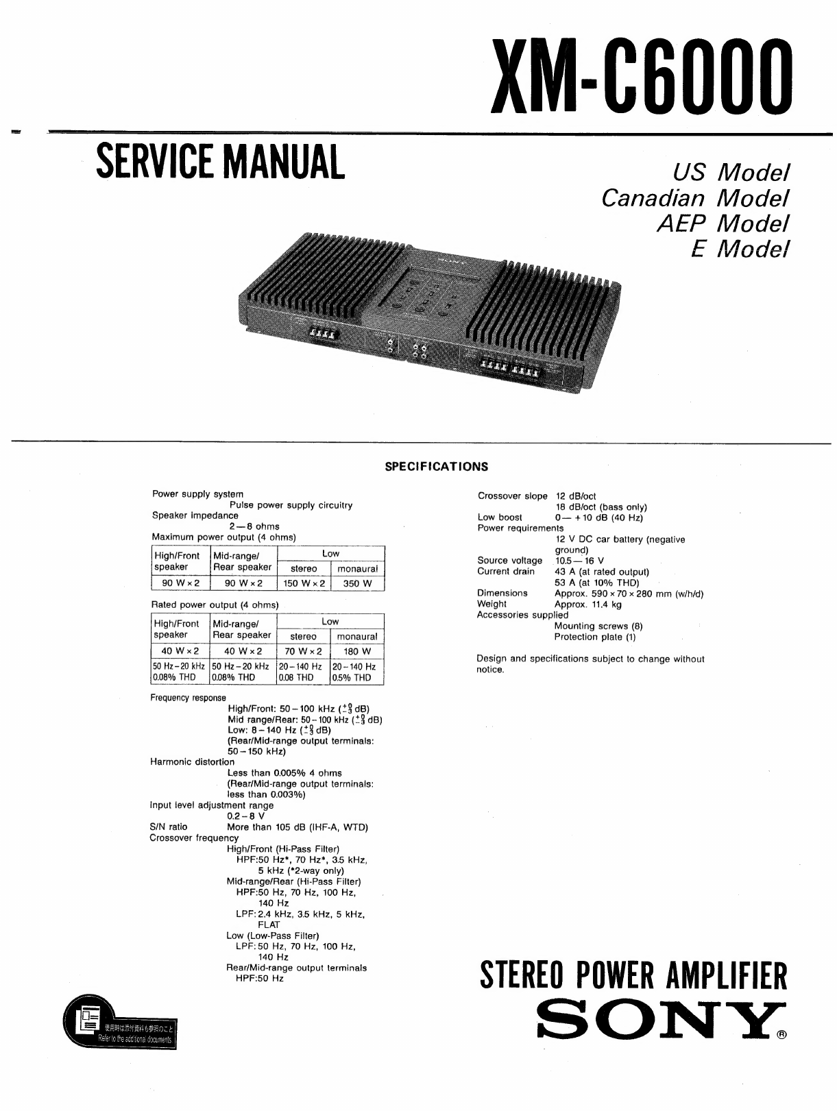
Sony XM-C6000 User manual

XM-C6000
SERVICEMANUAL
sie
ehh
Canadian
Model
AEP
Model
E
Model
SPECIFICATIONS
Power
supply
system
Crossover
slope
12
dB/oct
Pulse
power
supply
circuitry
18
dB/oct
(bass
only)
Speaker
impedance
Low
boost
O—
+10
dB
(40
Hz)
2—8
ohms
Power
requirements
Maximum
power
output
(4
ohms)
12
V
DC
car
battery
(negative
:
;
a
ground)
High/Front
|
Mid-range/
oe
Source
voltage
105—16V
speaker
Rear
speaker
|
stereo
|
monaural
Current
drain
43.
A
(at
rated
output)
150
Wx2|
350W
53
A
(at
10%
THD)
Dimensions
Approx.
590
x
70
x
280
mm
(w/h/d)
Rated
power
output
(4
ohms)
Weight
Approx.
11.4
kg
a
Accessories
supplied
High/Front
|
Mid-range/
Low
Mounting
screws
(8)
speaker
Rear
speaker
stereo
monaural
Protection
plate
(1)
USE
UW
Ke
oe
ands
Design
and
specifications
subject
to
change
without
50
Hz—20
kHz
|50
Hz-20
kHz
}20-140
Hz
|
20-140
Hz
notice.
0.08%
THD
|0.08%
THD
0.08
THD
0.5%
THD
Frequency
response
High/Front:
50
—
100
kHz
(+8
dB)
Mid
range/Rear:
50-100
kHz
(*3
dB)
Low:
8~140
Hz
(*3
dB)
(Rear/Mid-range
output
terminals:
50
—
150
kHz)
Harmonic
distortion
Less
than
0.005%
4
ohms
(Rear/Mid-range
output
terminals:
less
than
0.003%)
input
level
adjustment
range
0.2-8V
S/N
ratio
More
than
105
dB
(IHF-A,
WTD)
Crossover
frequency
High/Front
(Hi-Pass
Filter)
HPF:50
Hz*,
70
Hz*,
3.5
kHz,
5
kHz
(*2-way
only)
Mid-range/Rear
(Hi-Pass
Filter)
HPF:50
Hz,
70
Hz,
100
Hz,
140
Hz
LPF:
2.4
kHz,
3.5
kHz,
5
kHz,
FLAT
Low
(Low-Pass
Filter)
LPF:
50
Hz,
70
Hz,
100
Hz,
set
nennn
STEREO
POWER
AMPLIFIER
SONY.

XM-C6000
*
The
built-in
2/3
way
switchable
crossover
network
enables
you
to
enjoy
the
multi-way
speaker
system
with
easy
installation.
©
Powerful
output
of
90
W
x4+150
Wx
2
max.
(90
W'x4
+350
W
max.
with
5
channel
connection).
*
Low
boost
(40
Hz)
for
heavy
and
powerful
bass
sound
which
is
usually
insufficient
in
a
car
audio
sysiem.
*
Built-in
Bessel
function
filters*
for
creating
a
smooth
sound
fink
between
bass
and
treble.
©
Pulse
power
supply**
for
stable
and
regulated
output
power.
SECTION
1
GENERAL
*Bessei
function
type
fitters
Most
of
the
currently
available
crossover
networks
use
the
flat
response
fitters
{Butterworth
type).
The
group
delay
characteristics
of
these
filters
are
considerably
inferior
to
those
of
the
linear
phase
filters
(Bessel
function
type)
used
in
this
unit.
While
the
conventional
flat
response
filters
are
susceptible
to
transit
distortion
in
the
audio
signais
ai
each
filter's
crossover
irequency,
the
Bessei
type
filters
in
this
unit
will
raduce
the
distortion
and
contribute
in
obtaining
the
optimum
hi-fi
sound.
**Pulse
power
supply
This
unit
has
a
built-in
convertor
which
converts
the
power
supply
from
the
DC
12
V
car
battery
into
high
speed
pulse
signais
by
the
use
of
the
semiconductor
switch.
These
signais
will
be
stepped
up
by
the
buiit-in
pulse
transformer
and
separated
into
both
positive
and
negative
power
supplies
before
converted
into
the
direct
current
again.
This
is
to
regulate
the
othewise
variable
voltage
of
the
car
battery.
This
light
weight
power
supply
system
provides
the
highly
efficient
power
supply
with
low
impedance
output.
Precautions
This
section
is
extracted
from
instruction
manual.
*
This
unit
is
designed
for
negative
ground
12
V
DC
operation
only.
¢
The
nameplate
indicating
the
operating
voltage,
etc.
is
located
on
the
botiom
exterior
of
the
unit.
«
Use
speakers
with
impedance
of
2
to
8
ohms.
¢
Avoid
installing
the
unit
where
it
would
be
subjected
to:
—high
temperatures
caused
by
direct
sunlight
or
hot
air
from
the
heater.
—rain
or
moisture.
—dust
or
dirt.
°
When
installing
the
unit
vertically,
make
sure
that
the
fins
of
the
heat
sink
are
vertical
to
the
floor.
x
Not
this
way
O
This
way
@
When
installing
the
unit
horizontally,
make
sure
that
the
fins
are
not
covered
by
the
floor
carpet
etc..
°
If
the
unit
is
installed
too
close
to
a
car
tadio,
it
may
cause
interference
in
radio
reception.
In
such
a
case,
place
the
unit
away
from
the
radio.
©
If
your
car
is
parked
in
direct
sunlight
and
there
is
a
considerable
rise
in
temperature
inside
the
car,
allow
the
unit
to
cool
off
before
operating.
©
This
unit
has
a
built-in
protection
circuit*
to
protect
the
transistors
and
speakers
if
the
amplifier
malfunctions.
However
do
not
attempt
to
test
this
protection
circuit
by
covering
the
heat
sink
or
overloading
the
connections.
°
For
the
road
safety
reasons,
keep
the
volume
of
the
head
unit
moderate
so
that
you
will
be
able
to
hear
the
sound
outside
your
car.
If
you
have
any
questions
or
problems
concerning
this unit
that
are
not
covered
in
this
manual,
please
consult
your
nearest
Sony
dealer.
*Protection
circuit
This
unit
has
a
built-in
protection
circuit
which
operates
in
the
following
cases
when:
~—the
unit
is
overheated.
—a
DC
current
is
generated.
—the
speaker
terminals
are
short
circuited.
When
the
protection
circuit
is
activated,
the red
indicator
will
light
up
and
there
will
be
an
abrupt
loss
of
the
sound
from
the
speakers.
If
this
happens,
turn
off
the
connected
equipment
and
take
out
the
cassette
tape
or
CD
from
deck
and
determine
the
cause
of
the
maltunction.
If
the
unit
becomes
overheated,
wait
until
it
cools
down.
PROTECTOR
indicator
(red)
POWER
indicator
(green)
Fuse
Replacement
|
{f
the
fuse
blows,
check
the
power
connection
and
replace
the
fuse.
If
the
fuse
blows
again
after
replacement,
there
may
be
an
internal
malfunction.
in
such
a
case,
consult
your
nearest
Sony
deater.
Warning
Use
the
specified
fuse
with
correct
amperage.
Use
of
a
fuse
with
higher
amperage
may
cause
serious
damage
to
the
unit.
eo]
iy
[oy
[>]
SUB
WOOFER
section
[1]
LOW
BOOST
(40
Hz)
contro!
For
boosting
the
lower
audio
frequencies.
Frequencies
around
40
Hz
can
be
boosted
to
the
maximum
of
10dB.
[2]
LOW-PASS
(filter
selector)
switch
For
selecting
the
crossover
frequency
Cut-
off
point
of
the
low
frequency
output
signals.
Frequencies
above
the
selected
point
will
be
cut
off.
i3]
PHASE
(phase
invertor)
switch
If
set
to
the
—
position,
the
phase
of
the
sub-woofer
outputs
will
be
inverted
without
changing
any
connection.
[4]
LEVEL
(output)
control
For
adjusting
the
output
level
of
the
low
frequency
audio
signals.
FRONT
MID/REAR
FULL
section
[5]
LEVEL
(output)
control
For
adjusting
the
output
level
of
the
mid-
range
audio
signals
or
that
of
the
rear
Speakers.
[6]
FRONT
(3
WAY)/REAR
(2
WAY)
(selector)
switch
For
selecting
the
2-way
or
3-way
audio
signal
output
system.
17]
HI-PASS
(filter
selector)
switch
For
selecting
the
crossover
frequency
cut-
off
point
of
the
middie
range
or
rear
speakers.
Frequencies
below
the
selected
point
will
be
cut
off.
|B]
LOW-PASS
(filter
selector)
switch
For
selecting
the
crossover
frequency
cut-
off
point
of
the
mid-range
speakers
in
the
3way
connection.
Frequencies
above
the
selected
point
will
be
cut
off.
in
the
2-way
system,
set
this
switch
to
the
FLAT
position.

XM-C6000
Installation
—
FRONT
TWEETER/FRONT
FULL
section
{9
PHASE
(phase
invertor)
switch
lf
set
to
the
—
position,
the
phase
of
tweeters
will
be
inverted
without
changing
any
connection.
Note
if
used
in
a
2-way
system,
set
this
switch
to
th
+
position.
:
110)
HI-PASS
(filter
selector)
switch
For
seiecting
the
crossover
frequency
cut-
off
point
of
the
treble
or
the
front
speakers.
Frequencies
below
the
selected
point
will
be
cut
off.
Note
lf
used
in
@
3-way
system,
this
switch
to
the
5k
or
3.5k
position.
Never
set
it
to
the
50
or
70
position.
tf
you
do
so,
the
sound
wilf
not
come
out
in
order
to
protect
the
speakers
it
used
in
the
2-way
syslem,
set
it
to
the
50
or
70
positron.
Caution
¢
Before
making
any
connections,
disconnect
the
negative
ground
terminal
of
the
car
*
battery
to
prevent
short
circuiting.
*
Connect
the
red
power
lead
only
after
all
other
leads
have
been
connected.
*
Be
sure
to
connect
the
ground
wire
of
the
unit
securely
to
a
metal
point
of
the
car.
A
loose
connection
may
cause
a
malfunction
of
the
unit.
lf
you
place
the
power
lead
too
close
to
the
input
or
output
leads,
it
may
cause
some
audio
noise.
Try
to
place
them
away
from
each
other.
Due
to
the
built-in
high-power
amplifier,
make
sure
that
the
speakers
have
adequate
power
handling
capacities.
If
you
use
the
speakers
with
lesser
capacities,
such
as
the
ones
supplied
to
a
car,
they
can
be
damaged.
Do
not
connect
the
©
terminal
of
the
speaker
system
with
the
car
chassis,
and
never
connect
the
©
terminal
of
the
right
speaker
with
that
of
the
left
speaker.
If
your
car
is
equipped
with
a
computer
navigation
system
etc.,
do
not
disconnect
the
negative
ground
wire
from
the
car
battery.
If
you
do
so,
the
memories
of
the
computer
may
be
erased.
in
such
a
case,
make
the
connections
without
removing
the
ground
wire but
be
sure
to
connect
the
+
12
V
input
lead
only
after
all
the
other
connections
are
completed
to
avoid
short
circuiting.
[
installatin
of
the
Protection
Plate
Connections.
[11]
LEVEL
(output)
contro!
For
adjusting
the
output
level
of
the
treble
or
the
front
speakers.
[12]
POWER
indicator
Lights
up
in
green
when
the
power
is
turned
on,
[13]
PROTECTOR
(protection
circuit)
indicator
The
red
indicator
light
wil
come
on
when
the
protection
circuit
is
activated.
The
function
of
the
unit
ceases
at
the
same
time.
114]
REAR/MID-RANGE
output
terminals
When
used
in
a
3-way
system
or
if
another
pair
of
rear
speakers
(full-range)
are
desired
to
be
connected
for
more
mid-
range
sound,
an
extra
amplifier
can
be
connected
to
these
terminals.
Make
the
connections
as
illustrated
below.
When
ail
the
connections
are
made
and
all
the
settings
of
the
controls
and
switches
are
compieted,
attach
the
supplied
protection
plate
to
prevent
the
settings
of
switches
and
controls
to
be
accidentally
changed.
Before
Installation
*
Choose
the
mounting
location
carefully
so
that
the
unit
will
not
interfere
with
the
normal
driving
functions
of
the
driver
and
that
the
unit
will
not
be
exposed
to
direct
sunlight
or
hot
air
from
the
heater.
©
The
board
to
which
this
unit
is to
be
mounted
has
to
be
more
than
15
mm
thick
and
sound.
¢
Do
not
install
the
unit
under
the
floor
carpet
where
the
heat
dissipation
from
the
unit
will
be
impaired.
:
If
you
find
it
difficult
to
install
the
unit
for
yourself,
consult
the
dealer.
|
Trunk
installation
i
Prepare
a
sound
mounting
board
with
enough
thickness
(more
than
15
mm)
to
install
the
unit
securely.
Place
the
unit
directly
onto
the
mounting
board
and
mark
the
eight
bolt
holes,
then
drill
the
hoies
(3
mm
dia.).
full-ranges
Exampie
of
the
switch
settings
poe
T
T
tee
ee
Seiunnaaaicaaianin
ieaiammeaneameeieion
|
|
FRONT
MID)
|
FRONT
MID)
|
FRONT
|
!
Switeh
|
easel
(3
WAY)/
|
SUB
WOOFER
|
REAR
FULL
|
REAR
FULL
|
TWEETER/
|
i
EAR
(2
WAY)
|
LOW-PASS
\
HI-PASS
|
LOW-PASS;
FRONT
FULL
;
i
Ms
Or
can
ele
el
oe
i
epowt
awary
|
|
Setting
:
any
position’
{
any
position’
|
FLAT
\
50
or
70
|
|
|
*
i
i
i
|
Armies
peor
aoe
eae
a
*
Select
the
position
of
your
choice.
Notes
*
The
baiance
of
the
outputs
between
the
front
and
rear
Speakers
can
be
adjusted
by
the
fader
control
of
the
head
unit.
*
The
output
level
of
the
sub-woofers
will
not
be
affected
by
the
fader
control.
10
—
3-

XM-C6000
iiss
satel
9
i
seein
rime
[
3-Way
System
Front
mid-ranges
Power
amplifier
sub-woofers
Rear
full-ranges
Example
of
the
switch
settings
Example
of
the
switch
settings
f
oof
]
a:
FRONT
+
ere
|
FRONT
MID)
|
FRONT
MID/
]
]
|
FRONT
|
|
Switch
|
FRONT
S
pd
|
SO
eae
|
REAR
FULL
REAR
FULL
|
Weer
|
|
gwiten
|
FRONT
(3
WAYy
|
suB
WOOFER
!
Se
ROT
|
TWEETER,
|
|
|
HePASS
LOW-PASS
|
eags
|
REAR
(2
WAY)
|
LOW-PASS
|
FRONT
FULL
|
Hie
eee
ae
ok
St
|
:
:
HEPASS
|
LOW-PASS
|
|
fh
4
+
4
s
-4+—
|
i
'
i
|
:
Hi-PASS
i
|
i
“|
}
——
“+
—
——-
poe
nh
|
i
FRONT
(3
WAY)
3
|
i
I
T
i
i
i
|
Setting
|
t
any
position*
any
position*
|
2.4k,
35k
or
5k
3.5k
or
5k
|
roooe)
!
}
!
I
!
:
\
: j
|
Setting
|
et
|
any
position*
i
any
position®
|2.4k
or
35k
or
5k;
3.5k
oF
5k
i
Laacush
sepa
MNO
Mad:
2.
Sao
L
|
.
te
|
|
|
|
me
1.
-
ape
ed
aera
nN
ee
eae
wae
i
*
Sel
ni
ition
of
ir
choice.
7 :
Select
the
position
of
your
choice
Select
the
position
of
your
choice
Notes
Notes
°
Set
the
fader
control
of
the
head
unit
to
the
center
:
position,
If
the
fader
is
set
to
the
rear
side,
the
ig
pos
led
pe
eel
allie
ceded
be
ioe
rs
voiume
of
the
front
tweeters
and
front
mid-ranges
the
rear
aseakars
Pe:
at
'
-
se
be
lumned
cown
A
©
The
output
level
of
the
sub-woofers
will
no!
be
@
output
level
of
the
sub-woofers
will
not
be
affected
by
the
fader
control
affected
by
the
fader
control.
11
12
Examples
of
System
Connection
Connections
of
the
Leads
ic|+
REM
OUT
Blue/white
striped
5
Rear
sub-woofer
mid-ranges
tweeters
(monaural)
Power
amplifier
The
system
illustrated
here
is
just
an
example.
3-way
system
with
additional
full-range
speakers
[B|
Jo
the
metal
part
of
the
car
Note
tf
you
wish
to
use
a
sub-wooler
as
a
monaural
speaker,
connect
the
speaker
as
illustrated
above,
the
output
signals
of
the
sub-woofer
will
be
the
combination
of
both
right
and
left
output
signais.
ic]
To
the
accessory
position
of
the
ignition
key
panel
which
is
energized
at
all
times

Output
Adjustments
When
you
are
installing
either
a
2-way
or
2-Way
System
3-way
system,
adjust
the
balance
of
the
mid-
1
Turn
down
the
volume
of
the
head
unit
range
sound
first,
then
the
high
and
finally
the
completely.
Then
adjust
the
crossover
low.
frequencies
to
fit
the
connected
speakers’
Make
sure
that
the
bass
sound
is
turned
down
frequency
response
ranges.
See
page
17
compietely
while
adjusting
the
treble
and
the
about
the
crossover
frequencies.
mid-range
sound.
{f
the
bass
sound
is
present,
Set
the
FRONT
MID/REAR
FULL
LEVEL
it
will
be
difficult
to
balance
the
overall
sound.
and
the
FRONT
TWEETER/FRONT
FULL
After
these
adjustments
are
completed,
turn
up
LEVEL
controls
to
the
center
positions
and
the
bass
and
adjust
the
whole
balance.
the
SUB
WOOFER
LEVEL
control
to
the
MIN
position.
Playback
some
musie
and
turn
up
the
volume
to
a
moderate
level
with
the
head
unit.
Adjust
the
FRONT
MID/REAR
FULL
LEVEL
and
the
FRONT
TWEETER/FRONT
FULL
LEVEL
controls
to
the
optimum
level.
You
can
adjust
the
fader
control
of
the
head
unit
to
get
the
same
effect.
White
checking
the
congeniality
of
the
audio
relationship
between
the
speakers
to
be
smooth
and
natural
by
playing
back
some
music
with
a
lot
of
bass
sound,
adjust
the
SUB
WOOFER
LEVEL
contro!
to
balance
the
sound.
if
the
congeniality
of
sound
is
not
smooth,
readjust
the
LEVEL
controls.
lt
such
measures
do
not
improve
the
situation,
turn
down
the
volume
control
of
the
head
unit
completely
and
rearrange
the
settings
of
the
filter
selector
switches
and
then
readjust
the
LEVEL
controls.
7
Repeat
steps
1
to
6
until
the
optimum
sound
is
achieved.
ind
w
>
a
a
15
-
Output
Adjustm
ts
3-Way
.System
1
Turn
down
the
volume
of
the
head
unit
completely.
Then
adjust
the
crossover
frequencies
to
fit
the
connected
speakers’
frequency
response
ranges.
See
page
17
about
the
crossover
frequencies.
Set
the
FRONT
MID/REAR
FULL
LEVEL
and
the
FRONT
TWEETER/FRONT
FULL
LEVEL
controls
to
the
center
and
the
SUB
WOOFER
LEVEL
contro!
to
the
MIN
position.
3
Playback
some
music
and
turn
up
the
volume
to
a
moderate
level
with
the
head
unit.
Adjust
the
FRONT
MID/REAR
FULL
LEVEL
and
the
FRONT
TWEETER/FRONT
FULL
LEVEL
controls
to
the
optimum
fevel.
if
a
S-way
system
and
a
pair
of
full-range
speakers
are
installed,
adjust
the
balance
of
the
volume
of
the
front
and
rear
speakers
with
the
fader
control
of
the
head
unit.
While
checking
the
congeniality
of
the
audio
relationship
between
the
speakers
to
be
smooth
and
natural
by
playing
back
some
music
with
a
jot
of
bass
sound,
adjust
the
SUB
WOOFER
LEVEL
control
to
balance
the
sound.
id
a
wn
16
©
tf
the
congeniality
of
sound
is
not
smooth,
readjust
the
LEVEL
controts.
If
such
measures
do
not
improve
the
situation,
turn
down
the
volume
control
of
the
head
unit
completely
and
rearrange
the
settings
of
the
fiter
selector
switches
and
then
readjust
the
LEVEL
controls.
lf
the
congeniality
of
sound
between
the
speakers
is
difficult
to
achieve,
change
the
settings
of
both
PHASE
switches.
Adjust
the
SUB
WOOFER
LEVEL
and
LOW
BOOST
controls
according
to
your
taste.
Repeat
steps
1
to
8
until
the
optimum
sound
is
achieved.
Set
the
crossover
frequencies
by
changing
the
setting
of
each
filter
selector
switch
to
suit
the
frequency
response
of
the
connected
speakers.
See
the
diagram
below.
Setting
of
crossover
frequencies
.,
2
WAY
SUB
WOOFER
FRONT
REAR
LOW
MIDHIGH
LOW-PASS
FRONT
MI-PASS
S070
Hz
SOUTONDONNAO
Hz
REAR
HEPASS
SO/70/100/1a0
He
12
dBloc!
1B
aBioc!
3
WAY
MID
HIGH
MID-RANGE
Congeniality
of
Audio
Relationship
—Setting
of
Fitter
Selector
Switches
However,
in
some
cases
depending
on
the
different
types
of
car
and
the
tocation
of
the
speakers,
these
settings
may
implove
the
overall
sound,
if
the
bass
(LOW-PASS)
and
treble
(HIGH-
PASS)
filter
selector
switches
are
set
at
the
same
crossover
frequency
points,
both
audio
compasses
will
drop
by
3
dB
when
they
meet
and
the
overall
frequency
response
will
be
fiat.
See
diagram
(a).
if
the
filter
seictor
switches
are
set
to
different
frequencies,
the
overall
frequency
response
characteristics
may
have
uneven
sections.
See
diagram
(b)
and
(c).
-
(a)
(b) {c)
Paak
‘Overall
hequency
overall
frequency
response
ovetall
Kequency
response
response
Flat
chatacterisucs
characterauice
Dent
charactersice
ee
ase
e
LLL
Se
ee
WOR
sree
teeter
aware
MB
-
eee
eee
cane
ssateen
titer
°
characteristics
100
He
Hr
100
Hy
24
ehz
35
eee
(LOW
PASS.
sH-PASS!
(LOW-PASS:
LOWPASS)
=
pHLPASS;
HHEPASS:
17
|
Low
Boost
Characteristics
+410
(dB)
FREQUENCY
(Hz)
Block
Diagram
|
INPUT
OUTPUT
FRONT
(3
WAYI2
WAY)
Hi-PASS
{¥2dBvoct)
HIGHIFRONT
Fox
SOOT
5k/S
KH?
e
3.
WAY
Q
HI-PASS
LOW-PASS
.
(12¢Bvoct)
(reeBinee)
FAPOWER)
6
MIDIREAR
°
Fee
SO70N00/140
Ha
Fos
2
Akg
SWSKIFLAT
2
WAY
LOW
BOOST
Fo
340
Hz
e)
SUB
WOOFER
Gain
=
O-
«10
Hz
fd
LINE
OUT

DIAGRAMS
2-1.
BLOCK
DIAGRAM
RV701
pare
1€701
LEVEL
er
BUFFER
(FRONT
THEETER/)
e
ord
FRONT
FULL
ett?
’
ee
MID
ae
1¢702
(on
FULL
HI-PASS
PHASE
FRONT
(SWAY)
HI-PASS
(FRONT
TWEETER/)
7
SHIFTER
BAA
AY)
CIRCUIT
FRONT
FULL
Cm
;
==].
>
REAR(QQWAY))
2
=
1C703
o>
-
OPA
ee
|
2-STAGE
VARIABLE
Seats
a
4
|
S0H2
LINE
|
‘le
PASS
as
FTE
Tene
Baas
ra
i.
oD
ms
(
FRONT
FULL
)
3.5kHz
LINE
rie
ONLR
7
ie
LINE
SWAY
MODES
,
&
shi
ree
5kHz
CN717-3
inne
LEVEL
SW702-1
Heep
ae
|
BY)
ee
REAR
:
L
HI-PASS
6
OPM
1
FRONT
(SWAY)
HI-PASS
(Fou
MID/
culls
nae
pean
AY
CIRCUIT
_\REAR
FULL)
LOW-PASS
FRONT
ue)
ie
a
ee]
LOW-PASS
pout
MID/
2-STAGE
VARIABLE
REAR
FU
(rea
fut)
toh)
D
50Hz LINE
HIGH-
fat
FILTER.
CIRCUIT
aa
=
L_é
v
I
2-STAGE
VARIABLE
REAR
(WAY)
ee
TOH2
LINE
|
a
[S0Hz
LINE
|
LOW-
pes
FILTER
PRE
AMP
|
|
d
100Hz
LINE
4
i
70
aes
INE
—
OPO
140Hz
LINE
3.5kHz
LINE
as
aeaer
5kHz
LINE
aks
140Hz
a,
shi
LEVEL
FLAT
(su8
WOOFER)
10k-C
1¢709
INV.
GAIN
ull
see
IC710
LOWPASS
(qouee
EQUALIZER
cincurr
‘SUB
HOOFER)
bled
1C711
o>
6)
ww
7
1
O-STAGE
VARIABLE
-IC712
a>
)
S0nz
LINE
|
;
me
FILTER
PHASE
ye
|
B+
SHIFTER
|
70HZ
LINE
Lo
Pic
RV7Od
ACTIVE
!
PISO
Low
soosT|=~*
|
INQUCTOR
———
7B
sw707-1
(40H2)
140HZ
LINE
ne
(8
WOOFER)
Le
a,
aire
ce
4
(SUB
WOOFER)
10k-C
B—-
140Hz
‘s
T
IC713
2-STAGE
ges
L
9351
CN718-1
To
MUTE
aan
@;
R-CH
MUTE
POWER
AMP
&
Q102—113
R-CH
OVER
LOAD
POWER
AMP
Q302-313
DETECTOR
Qi14
R-CH
OVER
LOAD
DETECTOR
0314
Q@501
woe
POWER
AMP
@
Q502—-513
0718
OVER
LOAD
R-CH
DETECTOR
Q514
R-CH
OC
OFF
SET
PROTECTOR
OC
OFF
SET
PROTECTOR
&
OC
SHORT
PROTECTOR
Q720
+
L
£
)
CN708
SPEAKER
_
OUT
FRONT
TWEETER/
(R)
(
FRONT
FULL
)
R-CH
+
(L)
CN709
=
SPEAKER
OUT
Bs
(FRONT
Mlo/)
(R)
LREAR
FULL
R-CH
+
+
(LL)
CNTI6
7
SPEAKER
OUT
=
(
SUB
(R)
WOOFER
R-CH
+
1702
POWER
Bt28V
0715,
716
INVERTOR
RECT
Q721—728
8-28V
1701
POWER
INVERTOR
geen
Bt34V
0713,
714
RECT
B+15V
VOLT.
REG.
Q707,
0710
VOLT.
REG.
Q707,
D710
B-34V
PROTECTOR
DC-DC
CONVERTER
(RATCH)
ORIVER
Q705,
706
1¢714
B-15V
REMOTE
SWITCHING/
OVER
VOLTAGE
PRPTECTION
Q701—704
gL
“0718
(POWER)
a
LED
DRIVE
Q709,
711
MUTE
DRIVE
Q710
0717
a
(PROTECTOF
¢
SEMICONDUCTOR
LEAD
2SA988-PAFAEA
25C1845-EA
2SA1358-Y
letter
side
ie
|
a“
€
cé
2SA1481-F
29C2785-HFE
fatter
side
2SA1671-Y
2SA1672-Y
2SB1094-L
2SD2012
LAYOUTS
28C01815-Y
28C3327-A
28C3421-Y
28C4386-Y
2SC4387-Y
2SK1191
G
f
DS
188176
FIOP20F
(R)
:
F1QP20FR
FMG-32R
FMG-32S
LN-233RP
LN-333GP
anode
|
cethode
RD3.6ES-B1
RD6.8ES-B2
RD15ES-B3
RD18ES-B2
cathode
~
anode
XM-C6000

XM-C6000
|
*
SEMICONDUCTOR
LOCATION
Note:
[reef
|
wooo
Q403
H~26
0404
0405
Q406
Q407
Q408
Q409
Q410
Q414
0412
Q413
a414
0451
Q501
Q502
Q503
Q504
Q505
Q506
Q507
Q508
Q509
Q510
Q511
a512
0513
0514
Q551
Q601
a602
Q603
Q604
Q605
Q606
Q607
i
OO
@
@
i
BRN
WWW
i
Q6é08
Q609
Q610
0611
aQéi2
i
]errrme
i
Ow
AN
W
I
Q613
Q614
Q651
Q701
Q702
t
o0o0o0zre
4
Nw
Sawa
{
0703
Q704
Q705
Q706
Q707
i
Tmmmm
orxAa~~2o
i
Q708
Q70g
Q710
Q714
Q712
1
!
mmnng
i
Aoeoong
Q713
Q714
Q715
Q716
Q717
aoommm
“N
@®
O1
C1
OF
[Fer
ne
[
tater
|
B-5
2CH
BOARD
D717
E-9
D718
F-Q
LED
BOARD
D717
D-11
D718
D-12
*
O-—!:
parts
extracted
from
the
component
side.
:
Pattern
on
the
side
which
is
seen.
PRINTED
WIRING
BOARDS
¢
Refer
to
page
8
for
Semiconductors
Lead
Layouts
ae
a
ae
|
3
|
4
|
©
6
|
CNJ707-1
lo
2
20}
BRN
13
14
19
16
17
18
L
20
|
24
23
24
29
XS
Yn
2;
2°
0)
31
32
33 34
CNU702-
CN701
REMOTE]
[+12V]
[GND]
[LED
BOARD]
CNJ
703-2
CNU704~-2
Sw70l
PHASE
aise
TWEETER)
FRONT
FULL
+
—2way
Lt
ONLR
SWAY
MODE
CN7i6
Sw702
(hear
fit)
FRONT
(3WAY)
REAR
(2WAY)
Sw704
(REN
AY)
40Hz
t
|O0Hz
1
7OHz
SOHz
SPEAKER
OUT
ise
COPE)
SO
MONO
@®
@—1—0
O—r—
©
SW706
LOW-PASS
(wéoren)
40Hz
!
(0OHz
TOHz
5OHz
[CHD
BOARD]
{4
CH
BOARD]
f
r—
70Hz
t
[—
SOHz
—ONLR
2WAY
MODE
CN708
SPEAKER
OUT
(FROM
Pea)
FRONT
FULL
OUTPUT
H/M
BOARD
SW703
W705
$W707
LOW-PASS
(FRONT
TWEETER”)
(FRONT
MID/)
(ysuca)
FRONT
FULL
REAR
FULL
WOOFER
ae
ii
4s
3.5kHz
SkHz
3.5kHz
f
2.4KHzZ
[RCA
BOARD]
CN7I7
INPUT!
SPEAKER
OUT
FRONT
MID/
(Beg
AUEL)
CN7I8
OUTPUT
H{-
PASS(SOHz)

2-3.
SCHEMATIC
DIAGRAM
1
2 3
4
5
6
7
| }
|
8
9
10
11
12
13
14
15
16
17
18
19
20
21
22
23
24
25
26
27
28
29
30
31
XM-C6000
>
W702
>
———_——_
ee
-
HD
BO
-
HD
BOAR
IC702
(BN
A’)
tS
4CH
BOARD
ais
NJM4580L
FRONT
(3WAY]
ulti
(1/3)
PHASE
SHITER
.
A
(
FRONT
TWEETER?
Sa
ee
FMCa2s
Eg
REAR
(2WAY)
FRONT
FULL
|
earl
Zz
EMITTER
FOLLOWER
He
ee
|
PHASE
ote:
Ex
D715
1702
CNTI7
(
ee)
SW702
-|
aio.
Tei?
lane
are
ow
dekc}
eae.
Q102
,
103
Ql06
Ql09
D103
Qll2
D201
,202
Q202
,
203
Q206
D203
Q209
Q2l2
Qa
Eel
:
gee
_
Ea,
is
POWER
.
.
.
2
ve on
on
Ja
ee
meee
sl
de
SITS
ZSCIRS
PSNI
Se
AICH
Bley
SITE
aataigg
—ssiTs
a
gcibg.
ganeag
158176
zensaal
astesas,
25467
I
ire
+
All
capacitors
are
in»
F
unless
otherwise
noted,
pF
:
u
1
F
iol
aera
10k
10/16V
clos
047
$w703-I
14.7
2-STAGE
VARIABLE
an
220
AMP
AMP
EMITTER
FOLLOWER
ane
SE
ene
PASE
FOLLOWER
FINAL
STAGE
_
ie
5OWV
or
less
are
not
indicated
except
for
electrolyti
-|
1O/16V
ONLY
sy
Bie
jay
=
ips
C110,
0.47,
a
3
(8)
HIGH
PASS
FILTER
16V
Q104,
105
C151
5p
Qlio
Q204.205
Q2i0
EMITTER
FOLLOWER
Han
evdoaleneatene
a
lera.
cep
r
electrolytics
-L-
Aw—)
-|
3WAY
MODE
10k
C150,
eRI5O
2SAl015
-—
251358
h
re
ag
Se
0.1
F21500
-1500
7220
and
tantalums.
RIO!
e—W\-
(8)
C107,
0.33
CHL,
0,33
S
(2)
Qlol
10/i6v
INPUT
STAI
2SA1015
2SA1358
ae
Ik
RIOS
1
1
p>
0,
ie
ee
GE
AMP
RIS!
10k
|
EMITTER
FOLLOWER
INPUT
STAGE
AMP
EMITTER
FOLLOWER
RiG7
10
Ce
ve
>
All
in
2
and
!
j
aan
=
C108,
,0,0068
|
cil2
0.0068
On
5
r0
i
A
.
Ww
—$#
°
a
peer
One
an
resistors
are
in
2
and
%W
or
less
unless
otherwise
i
.
@
eps
clo2
ee
k
(3)
;
cum
f
|
pate
(4)
a
es
aie
4
*
°
~
t
4
ao
L704
specified.
100p
Leos
c109,
0.0047
ps
Vall
ee
‘
ogee
wor
[
a
TRI
Y
giog
|.28,
D103
Ri10z
1252
CH
TR2
¥
ga9q
0203
oo
ae
TSH
|
os
thera
Lerso
ao
16g:
Sie
tin
atbe:
ta
laraneg:
as
ark
aid
tens
[rile
kriz
ey
WaT
MODE
tLE7I3
10k
26.8
BRD
10k
To.
EuI800
onig00
o220
(0)
Ov
75.6
‘
een
|B-|
l
.
$20k
20k
$20k
20k
3,5kHz
TeV
08
Se
“Abate
sv
‘Tasv
Tor.
Q723
+
EW:
nonflammable
resistor.
¥
:
0
“
s
|
SkHz
[B=
|
alia
er
AFOk
-
EERE
8+
Line
T
Net
oa
0
)
az
9214
L
ea
i
|
iKomdek
Lexder-§
jj
.
t
C153
0
;
SS
250536
1
[B—|
a
4
Q72l
,f22
mM
(eaers
iar)
lowdeh
Llowder:'
SW702-2
bd
?
if
]
I
Qiol,
201
ain
vie
'
ERGTECTOR
\
SPEAKER
D716
-“07I6
4.4
Q725-728
_
ida
co
2sc36
;
LB
#B—
Line
FURR
14.7
[Lever
|
NIM4580L
R206
RS
ep
rer
vee
en
me
aes
2503327
aosala
j
ese
—
Q2ti
case
FMGeen
ae
nel
ne
*
Power
voltage
is
dc
14.4V
and
fed
with
regulated
dc
power
C20
FRONT
TWEETER
/
PREAMP
WW
ier
C206,
0,47
C210
mune
3,3k
0.6
-
2SAl0
TWEETER
EMITTER
FOLLOWER
;
-2
10716V
(
FRONT
FULL
R205
+
:
10)
(0.47
ve
iS
i
a
=
supply
from
+12V
and
REMOTE
terminals.
-a-@
A
5}
ral
ere
1OK-¢
)
10k
lea
os
|
a
0,33
(6)
ave
gzo1
2
v7.4
le
‘
:
<
Qil4
aU
EROTECTOR
aE
Bes
D713.
FIOP20F
Q716-
719
=
a
‘
sia
-
INPUT
MODE
SWITCH
:
STEREO
:
ee
rar
Ae
i
ee
ies
ee
r
ee
Ta
sale
uate
SEN”
ame,
ai9
rect
254113
Teste
Sno
oe
|
R204
AER
C208,
,0,0068
:
,
0
26.8
.
470k
INVERTOR
:
PROTECTOR
ON
I
“bbe
0
opt
ive
oa
9
i;
a
“
ee
:
R153
Frisa
-Lcis2
R157
‘
Qllo
er
;
rer
“ld
|
i
AMER
ae
2
ae
reer
°
-
gene
e
I
Vol
k
:
ith
a
VOM
i
Q
p
OW
:
eae
d
ae
oa
199.0047
oy
Raia
euane
sre
0,87
RSS
|
47k
Tat
Fi00
Q2i0
[i
yar
R725
DRIVER
sie
Ji
oltages
are
taken
with
a
(Input
impedance
10M
®).
204
BR208
R20
oan
eae Ree
aes
k
=
501
2s
ES
=
6256
R
tor
120
(3W1
Pere
ee
5,
==
CONVERTER
p44
Voltage
variations
may
be
noted
due
to
normal
produc-
ES
in
;
;
20k
S20k £20k
S20k
Seaur
May
70.001
+
&
>.
-
+
¢:
.
J
:
|
¢
eyo)
,
GEE,
iq
7
(
REAR
FULL
)
)
|
—w
4
R251
1k
|
{267,10
'
ate
ee
tion
tolerances.
*
7
ove
ik
2st
2scis
5
ct
2
ASa6
eee
0208
C25
}
F
|
oO
C724
ae
==0.1
Spon
7200
*
Signal
path
=
i
2
TES)
alt
Tow
dels)
.
tT
B+
Bi
a
wear
ae
Suit
Hat
Siren
COOH
2nd
STAGE
AMP
erie
ie
ox
I
.
.
;
0.1
ER5800
at
ype
L-CH
(A-CH)
R308
[R309
[R310
[R3Il
PROTECTOR
:
SOV
50V
oo
.
NO
ANC
306
oar
getnget
gsi
go
oe
nl
may
=O
Tipton
SW705-|
DR
See
OSU
ees:
1
SReaR
a.
“sae!
Q309
Q402,403
9406
=
Q408
9409
Q4i2
413
Yo)
1
Ale
H/
My
|
_
>
és
oO
SO,
suoe-s
Pea
I
Ffeotay
9
ee
iit
a
neitesice
250
sit
ral
nos
|e
iFoclais
—2sngee
—2sclsis
283421
284586,2SAI671_
UH
ae
fia
-3
10/16V
R306.
.
2
5
(=
}
D7I7
D718
--L-@
w—)
5)
p
a
en
3
|
aula
I
’
Cale
One
ee
|
my
|
ca
nv
alae
ype
R389
Ik
ae
A
R351
ok
|
1SSI76
TOWER
en
uli
FOLLOWER
EMITTER
FOLLOWER
R367
10
TOOK
|
721
mets
(PROTECTOR)
(ROWER)
R301
0
Pius
Ea
|
ee
j
a7
0308
0.22
C3i
0.33
R322
G)
a
a
Sea
bd
*
M$
i
}
O
.
P+tLC723
th
599
25C536
ik
6)
‘304
Io/iev
1
gp
—@
IF
1k
+
SOHE
Q
4
jae
Cr
See
|
oak
0b
g
q
i67iev
°
|
[
+
©
“
TSOy
TP
SOY
4.8
FOLLOWER
s
Zz
.
e
--4
#
Li
sae]
—@
are
ie
Cal
Pb
6309
pu
ade
rt
“8.7
Tas20
100
A
ie
R852
4CH
TR3
Y
qaoe
nae
rasel
(CH
TR4Y
caog
0903
0403
|
|
[oe
°F
g7ia,7i5
[LED
BOARD]
c302
32k
R303
R304
L305
1-3)
O
it
+h
V
Ni
:
3.5
kHz
Tordeka
[lenacl:}
(0)
R325
BOARD
5.9k-F
RASS,
oT
Tt
BoA
0409
|
og
ISSI76
—-gRA7O
eye
|
100p
47k
47k
atk
C313
012
loOHz ER3IG
j
R324
Ok
2526
4tk=
RD
28.1
gale
10k
0,047
L
*
2SA
1481
®
Paglesalesieis
it
Seber
Kor
dowd
Tek
deX=)
sue
Teai7
tI
NUM
4580L.
3.5k
DBO!
D401
hone
7X
a
&
RAGS
-14%9
708
[5
|
ie
EMITTER
D717
LN233RP
|
147
Rae
RS
2Oke
DORE
140He
NJM4580L
*
Joos
2-STAGE
VARIABLE
APY
cae
Ay,
rr
Jal
R468
|
=22.1
20
|
|b
i
b7la
dodo
|
B=!
]
Z:SIAGE
VARIABLE
aa
LOW-PASS
FILTER
26.8
aos
|
AL”
ane
Aro
1
70g
((2W)
——sa
eae
D718
LN333GP
(REAR)
HIGH=Pass
FIL
|
Ll
Q4i4
Q4l4
[z]
O}O
H)
he
“
RABE
2$C536
2SB1375
D710,
7H
Tew
deys}
Sw702
Genes
1B
ie
nS
et)
|
G3?
se20T
y
OVER
LORD
RS68
MTZJ-15¢
[‘
CH
BOARD
1
FRONT
MID/
3
|
NUM4580L.
(
Roan
CUCL
page
tha0o
aa
ase
ww
—
(1/3)
BUFFER
FRONT
(3
WAY)
FRONT
MID/
406
0.47
a
ae
5.1K
Sw704-2
R752
Q702
cAol
ote
cei
WAY)
een
rl)
;
‘t
:
9
We
aes
2SA1358
0/16V
2WAY
lOK-C
i
mae
Wey
Q
ume
2
ens
rage
(OK
c407
ps
ia
-
J
5
940
9304
,
0
OVER
LOAD
;
0
Cf
2g
7
2SAl015
TH703
SWITCHING
R-
@—
5
+
er
tees
4
~26,8
ch
Q3l
q729
zl
PROTECTORIRATCH)
=
U7
ie
on
oe
iy
ca
fe
|
ape
:.
©)
;
ae at
;
ae
|
ja
;
0
R368
R754
C7.
rasa
|
O10
~~
ci
ply
P:
0.260
oviey
IND
9}
Ica09
0.12
C42
0,22)
.
R353
$R354
1352
R357
et
28.
|
;
25A1671
:
-28.
;
470k=
Fa
a
10
|
~
&.
y
°e
J
|
ie
.
;
ae
3552
7
47k
2
a3io
¥-28.
FINAL
STAGE
hee
10V
aw)
D707
—
709
2)
aa70)
c402
Bee
ow
|
7)
}
||
aN
9
47p__4
100
EMITTER
FOLLOWER
:
+
3.3K
100p
it
Ob
9
Cai3
0.12
R420
100
bird
Coa
The
e
sive
Be
1SSI76
4,8
47
36
|
pl4-3
Heo
Ns
a
.
oe
R413
|
R414
LR4I5
6,001
—*
®
e
e
o
.
f
|
10V
14.3
R718
Sa7i7
I
4]
5
|)
(0)
(6)
D703
Q701
°) °)
I
20k
20k
S20k
S
20k
Th
+
i
RAS!
10k
RAG?
10
oe
3.3k
0
-3.3k
mee
(1915)
4-19-11)
109)
MTZJ-3.6A
ae
sp
3,7
©
|
!
caso.
R450
304,305
307-308
Q310
Bil
401,402
4
if
5
ace
|
rrr
|
©
pit
tor
:
ned,
=
oriey
ik
’
Q3ll
1
Q404
,405
Q407
Q410
Q4I|
Q729
2SC536
3
-
a
IC
TOS
RICT
12
=
|
4
PSO,
SCRE
SEINE
aaalsa®
SRO
Issivé
sali,
ascisal
it
—
2A
ZSAIOIS
|
emoTesTen
fe
dh
7
eam
|
bens
gro
[Eon
TER
_
OUTPUT
ic714
—e
7
i
ES
eee
(
GRONT
MD?
)
a
4
aye
a
a
a
RO
AMP
5p
FOLLOWER
SHORT
PROTECTOR
lun
DC
SHORT
PROTECTOR
=
D707
pa
(ive
lie
0
750
2SAl015
‘A
BOARD
ES
;
ce
EEE
ee
=
;
Me
++
PHY
el
if
sana
t
i
if
0718
i
R720
=
muses
05
|
"K
702
TOI
hae
|
.
10k
.
Seach
a7
ay
se
esos
Tesla
RSa
|
Roe2
issi7e.
ore
9706
D709
OO-~D-Q-Q-O-O-B®
'¢-4—|}—*
*
sir
a
tise
7
es
WG
onui
reais
L
sie
fal
hee
;
Q508
CBI
0503
Q5il
Q608
D603
Q6il
man
i
OH
aa
|
|
ara
73]
ft
TGR,
|
5.8
|
Of
S|
)P704
Ssnov
7
=
p
-
14.3
RTI
0
7
R704
aia
ee
R50
1%)
0
ais
ats
D
Gs
mel
l0k
9
@)
0550.
-
Gea
eon
K,
Issi?6é
—-2SAI015
2SC1815
ISSI76.
—-2SAl015
aN
(6)
Se
;
[jv
120
Fi20
=
Ik
+
is
Nt
3.94
"KR
t01
ark
@)
D
-
he
(O-#S)
°
33k
|
33k
[
-—o
Q
(6)
a50l
i
R55],
10k
SHORT
EROTEC
ae
QUTPUT
DC
RTI6
8k
|
+{c705
$R707
@;
Q
©320
=
Ow
|
<
(7)
t
4M
Nin
$
>
|
(1)
.
e—_
}2&—-wv
*
AW
in
OTECTOR
SHORT
PROTECTOR
[R567
10
R753
CHO
gR7al
470
+
A
C105
S330
Q704
|
C318
G
0)
381
eee
R332
l
@
On
ae
|
RBIS
RoI
(2)
p
On
ia
.
aK
XE
+
ra
J
Oe)
lee
6.01
#10k
croey
R7IO
(90
250536
ha
air
cae
@)
an
an
*
aaa
14.74]
Si
Shy
sone
=
a
R503
tere
rlL@
Cy
*
°
°
*
*
=f
=
|
x
Oe
56k
CONFROLLER
|
:
“14.7
:
R514
R518
7
10
2
R556
c3l9
;
aA
ass!
|
|
16k
6k
70H
“14.7
0.8
ic0z
|
CCH
TRI
Y
qso9|_
0503 R570
Res6e
F2CH
TR2
¥
eos
R569
|
C7
\
1
0.047
ee
I
“|
0,28
es0v
(p>
a
We
;
“147
(Oy
Raed
BOARD
&
7>v*7Rbe34
512
[420.1
ioKe
———°F
k_
BOARD
RoR
lz]
10
L
A
Ea724
Rv9
(0)
R330
LR33I]
1
c321
I
+
G
C)
ij
WK
Nk
100Hz
oe
SW
707
ene
27.4
a)
Kk
(>
29.14]
{
be
29.1
(IW)
Q706
+50v
5.6k
a7k
D705,
706
0704
9703
a
}
R328
R329
100k
S100k|
y
100p
C501
|
$R505
+
c752
Q506
ul
R564
29
R568
|
ISSI76
C714
100k
10k
2.2
|
¥
Ik
if
e503
1¢504
[e508
1506
ee
eV
0.01
a
0.6%
p56
[NES
A
Nosig
|
470k
Z8C536
ISSI76
250536
MTZJ-18A
50V
+
Sst
—q
6.47
[0.47
[0.47
[6.47
ae
ail
1;
1
laa
"
1)
Qel4
+
Tt
®
PARATCH
4CH
BOARD
ane
See
SWITCHING
070
VR703
R507
Cos
re
|
R565
[%0
C556
~
Y
2
1
|
|
_cn7ie
a
:
die
u
Q501
,
601
Le
ee
4
ps008560
(75)
Poe
ai
0
a8.
0,047
cNTI6
(1/3)
DutWr
MTZJ-6.88
C756
(SUB
WOOFER)
ee
||
OGC39e7.
R559
|
te)
50V
o
OVER
LOAD
ee
ae
at
OUTPUT
reo2
‘V5
[B—
|
oe
ETE
lase6
DETECTOR
——————————
ee
eee
5
&
REAR
eye
OK-C
Q551,651
a
MUTE
soa)
330
|as08
|
:
iE
igi.
ng
R743
MONO
|
SUB
)
I
-_
Raz?
:
(CHASSIS)
Weeted|
We
acto
8
eon
Beare
are
ne
5a
ion)
su
C42
a
SW706-2
-05
a
Calg
(2)
0
|
9451
0
Wiley
en
REOI
Real
fd
ee
|
CY
0513
Q514
alk
a
0
>
]
is
4 .
13k
0
R6le
fee
Or)
rez
“Ss
fee
O38,
Teess
©
Cale
©
Panes
3
cy
|
Bee
mh
NS4_
2
=28.1
DETECTOR
REGS
0.047
6.047
(4)
aa
I
i
|
REIS
Rel?
A
K
gsio
[7
28.!
7
al
wae
|
C
|
1
KA
10
R428
(Or
PiSy
gRasograail
|
caai
I
i
R6I4
:
RAG
Ps
aw)
R
100k
'oK
100k
100k)
|
100p
lok
\6k
1
0.87
Eee
‘
é
+
+
+
o
|
sc
R651
Ok
R667
10
(SUB
WOOFER)
"te
Ane
R620.
eowdeks)
Elow
ar
ms
5
R650
%
at
a
=o
?
O@
|
44
4
lok
-C
NUM4580L
33/i6v
IK
y
PHASE
SHIFTER
C65!
ph
ea
$0536
IC713
-
D501!
,502
Q502
,503
Q506
Q509
D6OI,602
Q602
,603
ee
‘a
Kerake}
=
’ ’
;
;
Q606
Q609
612
Q613
DC
_OFFSET
NJM4580L
|
issi76
2scigis
—-«-2Sa988_
=
2SC342
ISsi76
2SCi8I5
25988
2sc3d2l_2ScaS87
,
281672
oc
SHOR
PROTECTOR
ROTEL
Bon)
2-STAGE
INPUT
STAGE
2nd
STAGE
EMITTER
INPUT
STAGE
2nd
STAGE
EMITTER
FINAL
ST
‘
;
HIGH-
PASS
AMP
AMP
FOLLOWER
AMP
AMP
FOLLOWER
eivine
CaLLOWER
FILTER
;
4
10710
Q504
,505
Q507
Q310
Q5l2
513
Q604
,605
Q607
Q6l0
:
C711
nSAll5
25C1841
25A1358
2804387,
25A1672
2SA
1015
2SC
184
2SA
1358
Eh
NJM4580L
STAGE
2nd,
STAGE
EMITER
FINAL
STAGE
INPUT
STAGE
2nd.
STAGE
EMITTER
PE
algal
te
[2
CH
BOARD]
FOLLOWER
EMITTER
FOLLOWER
AMP
AMP
FOLLOWER
ae
me
es
LOW-PASS
FILTER
-
02
~
eo
hg
—_
14
—
2
peat
ames
—
18
—
—
19
—

XM-C6000
NOTE:
—XX,
—X
mean
standardized
parts,
so
they
may
have
some
differences
from
the
original
one.
The
construction
parts
of
an
assembled
part
are
indicated
with
a
collation
number
in
the
remark
column.
Color
indication
of
Appearance
Parts
SECTION
3
EXPLODED
VIEWS
e@
Items
marked
“*”"
are
not
stocked
since
they
are
seldom
required
for
routine
service.
Some
delay
should
be
anticipated
when
ordering
these
items.
The
mechanical
parts
with
no
reference
number
in
the
exploded
views
are
not
supplied.
SE
Example
:
KNOB,
BALANCE
(WHITE)....(RED)
@
Hardware(#mark)
list
is
given
in
the
last
of
this
parts
list.
t
Parts
color
Cabinet's
color
3-1.
MAIN
SECTION-1
Ref.
No.
Part
No.
Description
Remark
Ref.
No.
Part
No.
1
*
3-372-255-01
PLATE,
BOTTOM
1
*
1-641-619-11
2
*
3-372-263-01
LABEL,
MODEL
NUMBER
(US,
AEP)
8
,
deSed=226>14
2
*
3-372-264-01
LABEL,
MODEL
NUMBER
(Canadian)
9
*
3-372-258-01
2
*
3-372-265-01
LABEL,
MODEL
NUMBER
(UK,
E,
AES)
10
*
3-395-832-01
3
*
3-373-182-01
PLATE,
SHIELD
.
11
*
3-372-257-01
4
1-532-947-11
FUSE
(BRADE
TYPE)
(AUTO
FUSE)
12
*
1-641-612-11
5
*
3-372-275-01
PANEL
(FRONT)
(AEP,
UK,
E)
13.
1-641-612-11
5
*
3-372-275-11
PANEL
(FRONT)
(US,
Canadian)
14
*
3-396-106-01
6
1-537-348-21
TERMINAL
BOARD
(3P)
19
*
ADDITIONAL
|
INFORMATION
Description
:
Remark
FUSE
BOARD
HOLDER,
FUSE
(BRAID)
HEAT
SINK
(SUB
B)
SPACER
HEAT
SINK
(SUB
A)
2CHTR1
BOARD
2CHTR2
BOARD
BRACKET
(TR)
A-3273-687-A
2CH
BOARD,
COMPLETE

3-2.
MAIN
SECTION-2
Ref.
No.
Part
No.
Description
51
*
3-372-258-01
HEAT
SINK
(SUB
8)
52
*
3-395-832-0171
SPACER
53
*
3-372-273-01
HEAT
SINK
(R)
54
*
3-372-257-01
HEAT
SINK
(SUB
A)
55
*
1-641-6145-11
OUTPUT
H/M
BOARD
56
*
|-641-617-11
RCA
BOARD
57
*
3-372-276-01
PANEL
(REAR)
58
*
1-641-616-11
OUTPUT
(L)
BOARD
Remark
HM
FH
9
HE
3
Part
No.
3-372-272-01
A-32173-682-A
1-641-607-11
1-641-607-11
1-641-607-11
1-641-607-11
3-396-106-01
ADDITIONAL
|
INFORMATION
|
SEE
not
supplied
Description
Remark
HEAT
SINK
(L)
4CH
BOARD,
COMPLETE
4CHTR1
BOARD
4CHTR2
BOARD
4CHTR3
BOARD
4ACHTR4
BOARD
BRACKET
(TR)

§
F
F
ADDITIONAL
3-3.
MAIN
SECTION-3
INFORMATION
101
Ref.
No.
Part
No.
Description
Remark
Ref.
No.
Part
No.
Description
Remark
101
*
A-3273-690-A
CHANNEL
DIVIDER
BOARD,
COMPLETE
104
*
3-372-274-01
CHASSIS
(CENTER)
102
3-350-749-01
COVER
(SW)
105
*
3-372-277-01
PANEL
(CENTER)
103
*
1-641-618-11
LED
BOARD
106
3-350-753-01
KNOB
(VR)

NOTE:
SECTION
4
ELECTRICAL
PARTS
LIST
e@
Due
to
standardization,
replacements
in
the
parts
list
may
be
different
from
the
parts
specified
in
the
diagrams
or
the
components
used
on
the
set.
@®
—XX,
—X
mean
standardized
parts,
so
they
may
have
some
difference
from
the
original
one.
@
RESISTORS
All
resistors
are
in
ohms
METAL
:
Metal-film
resistor
METAL
OXIDE
:
Metal
Oxide-film
resistor
F:
nonflammable
Ref.
No.
C590
C551
C582
6553
C554
C905
C556
C650
C651
C652
C653
C654
C655
C656
C104
C702
C704
C705
C706
Cid?
C708
C709
C710
ee
He
HM
HH
Part
No.
A-3213-687-A
1-641-612-11
1-641-612-11
3~372-257-01
3~372-258-01
3-395-832-01
3~-396-106-01
1-124-034-51
1-102-942-00
1-101-880-00
1-101-880-00
1-101-880-00
1-123-380-00
1-130-491-00
1-124-034~51
1-102-942-00
1-101-880-00
1-101-880-00
1-101-880-00
1-123-380-00
1-130-491-00
1-136-366-00
1-136-366-00
1-126-235-11
1-126-101-11
1-102-074-00
1-124-443-00
1-126-176-11
1-123-306-00
1-102-129-00
Description
2CH
BOARD,
COMPLETE
KAKARERREREEREERA
ERS
2CHTR1
BOARD
2CHTR2
BOARD
HEAT
SINK
(SUB
A)
HEAT
SINK
(SUB
8B)
SPACER
BRACKET
(TR)
<
CAPACITOR
>
ELECT
CERAMIC
CERAMIC
CERAMIC
CERAMIC
ELECT
MYLAR
ELECT
CERAMIC
CERAMIC
CERAMIC
CERAMIC
ELECT
MYLAR
FILM
FILM
ELECT
ELECT
CERAMIC
ELECT
ELECT
ELECT
CERAMIC
33uF
9.
OPF
47PF
47PF
47PF
uF
0.
047uF
33uF
5.
OPF
41PF
47PF
47PF
luF
0.
047uF
Q.
tuF
Q.
1uF
100uF
100uF
0.
001uF
100uF
220uF
47uF
1O000PF
Items
marked
“*”
are
not
stocked
since
they
are
seldom
required
for
routine
service.
Some
delay
should
be
anti-
cipated
when
ordering
these
items.
SEMICONDUCTORS
In
each
case,
u:
uw,
for
example:
UA....2
wA....,
UPA...
PA...
uPB....:
«PB....,
uPC....:
wPC.
uPD....:
#PD....
CAPACITORS
uF:
uF
COILS
uH:
wH
Remark
Ref.
No,
Part
No,
Crit
1-124-463-00
C716
1-123-380-00
CTil
1~136-366-00
C748
1-124-343-00
C719
1-124-343~00
C720
1-124-911-11
C721
1-4124-911-14
C722
1-128-458-114
C723
1-128-458-11
C124
1-136-366~00
C725
1-136-366-00
20%
16V
C726
1-123-306-00
+-0.
SPF
50V
5%
50V
5%
50V
5%
50V
CNP702
1-564~-320-00
CNP703
*
1-564-705-11
20%
50V
CNP704
&
1-569-978-11
5%
50V
CNP706
*
1-564-704-11
20%
16V
CNP707
*
1-564~-241-00
+-0.
SPF
50V
5%
50V
5%
5OV
D501
8-719~802-30
o%
30V
D502
8-719-802-30
20%
50V
D503
8~719-802-30
5%
5OV
D601
8-719-802-30
o%
50V
D602
8-719-802-30
5%
50V
D603
8-719-802-30
20%
16V
D701
8-719-110-49
20%
16V
0702
8-719-109-97
10%
50V
D703
=
8-7
19-109-68
20%
10V
D704
8-719-802~-30
20%
10V
D705
8-719-802-30
20%
10V
D706
8-719-802-30
10%
50V
8-719-802-30
D707
When
indicating
parts
by
refer-
please
ence
number,
the
board
name.
Description
<
CONNECTOR
>
0.
uF
20%
1uF
20%
0.
1uF
5%
2200uF
20%
2200uF
20%
220uF
20%
220uF
20%
3900uF
20%
3900uF
20%
0.
1uF
5%
0.
1uF
5%
20%
47uF
PIN,
CONNECTOR
(B2P-VH)
2P
PIN,
CONNECTOR
(SMALL
TYPE)
3P
PIN,
CONNECTOR
(PC
BOARD)
?P
PIN,
CONNECTOR
(SMALL
TYPE)
2P
PIN,
CONNECTOR
(B4P-VH)
4P
<
DIODE
>
DIODE
188176
DIODE
188176
DIODE
188176
DIODE
18S176
DIODE
188176
DIODE
1S8S176
DIODE
RD18ES-B2
DIODE
RDG.
8ES-B2
DIODE
RD3.
6ES-B1
DIODE
188176
DIODE
188176
DIODE
188176
DIODE
188176
include
Remark
50V
50V
50V
50V
30V
50V
10V

10714
L501
L601
L701
L702
0501
Q502
Q503
—
Q504
0505
0506
Q507
0508
Q509
Q510
0511
0512
Q513
Q514
0604
0602
Q608
0604
0605
0606
0607
0608
0609
0610
Q611
Q612
0613
0614
Q701
oe
Part
No.
8-719-802-30
8-719-802-30
8~719-110-42
8-719-110-42
8-719-802-30
9-210-30
9-210-38
9-802-30
$e
8-
8-
8-749-802-30
a
YW
MN
ia
8-759-103-87
1-428-086-11
1~428-086-11
1-424-303-11
1-424-112-11
8-729-203-48
8-729-281-53
8-729-281-63
8-729-201-53
8-729-201-53
8-729-~140-82
8-729-184~-53
8-729-281-52
8-729~207-82
8-729-207-89
8-729-201-53
8-729-321-20
8-729-321-23
8-729-119-78
8-729-203-48
8-729-281-53
8-729-281-53
8-729-201-53
8-729-201-53
8-729-140-82
8-729-184-53
8-729-281-52
8-729-207-82
8-729-207-89
8-729-201-5383
8-729-321-20
8-729-321-23
8-729-119-78
8-729-201-53
Description
Remark
DIODE
188176
DIODE
188176
DIODE
RDI5SES-B3
DIODE
RDISES~B3
DIODE
188176
DIODE
F10P20F
(R)
DIODE
FIOP20FR
DIODE
188176
DIODE
188176
«
IC
>
IC
uPC494¢
«
COIL
>
COIL,
AIR-CORE
COIL,
AIR-CORE
COIL,
CHOKE
0.
26mH
COIL,
CHOKE
7.
5uH
<
TRANSISTOR
>
TRANSISTOR
TRANSISTOR
TRANSISTOR
TRANSISTOR
TRANSISTOR
TRANSISTOR
TRANSISTOR
TRANSISTOR
TRANSISTOR
TRANS
|
STOR
TRANSISTOR
TRANSISTOR
TRANSISTOR
TRANSISTOR
TRANS
[STOR
TRANSISTOR
TRANSISTOR
TRANS
I
STOR
TRANS
|
STOR
TRANS
|
STOR
TRANS
|
STOR
TRANSISTOR
TRANSISTOR
TRANS {STOR
TRANS
1
STOR
TRANSISTOR
TRANSISTOR
TRANSISTOR
TRANSISTOR
28C3327-A
28C1815~-GR
2501815~-GR
25A1015-GR
2SA1015-GR
2SA98B-PAFAEA
2501845-EA
2801815-Y
2803421-Y
25A1358-Y
25A1015-GR
2504381-Y
25A1672-¥
2802785-HFE
2503327-A
25C1815-GR
2301815-GR
25A1015-GR
25A1015-GR
25A988-PAFAEA
25C1845-EA
2501815-Y
2803421-Y
25A1358-Y
2S5A1015-GR
2504387-Y
25A1672-Y
2502785-HFE
25A1015-GR
R524
R525
R550
R551
R592
R993
RO04
RO06
R556
ROOT
R508
R009
R960
R561
R062
R563
R564
R065
R966
R567
R568
R569
R570
R624
R625
R650
R651
R692
Part
No.
8-729-207-89
8-729-119-78
8-729-119-78
8-729-201-53
8-729-419-78
8-729-209-15
8-729-111-87
8-729-201-5383
8-729-201-53
8-729-201-53
8-729-119-78
8-728-119-78
8-729-803-58
8-729-803-58
8-729~-322-52
8-729-322-52
8-729-322-52
8-729-322-52
8-729-119-78
1-249-429-11
1-249-441-11
1-249-417-11
1-249-429-11
1-249-42
1-11
1-249~-421-11
1-249-437-11
1-249-437-11
1~249-405-14
1-249-405-11
1-249-416-11
1-249-411-11.
1-249-411-11
1-249-393-1]
1-249-393-1]
1-249-417-11
1-249-417-1)
1-249-417-11
1-205-991-11
1-249-393-1]
1-247-895-00
1-215-857-11
1-249-429-11
1-249-429-11
1-249-441-11
1-249-417-11
1-249-429-11
1-249-421-11
Description
TRANSISTOR
2SA1358-Y
TRANSISTOR
2SC2785~-HFE
TRANSISTOR
28C2785-HFE
TRANSISTOR
2SA1015-GR
TRANSISTOR
28C2785-HFE
TRANSISTOR
2802012
TRANSISTOR
25B1094~L
TRANSISTOR
28A1015-GR
TRANSISTOR
2S5A1015-GR
TRANSISTOR
2SA1015~-GR
TRANSISTOR
2802785-HFE
TRANSISTOR
28C2785-HFE
TRANSISTOR
2SA1481-F
TRANSISTOR
2S8A1481~-F
TRANSISTOR
2SK1191
TRANSISTOR
=
28K
1191
TRANSISTOR
28K1191
TRANSISTOR
2SKi191
TRANSISTOR
28C2785-HFE
<«
RESISTOR
>
CARBON
10K
=
5%
CARBON
100K
5%
CARBON
1K
5%
CARBON
10K
=
5%
CARBON
2.2K
5%
CARBON
2.2K
5%
CARBON
47K
=
5%
CARBON
47K
5%
CARBON
100
5%
CARBON
100
=
%
CARBON
820
5%
CARBON
330
=
b%
CARBON
330
=
5%
CARBON
10
a%
CARBON
10
5%
CARBON
1K
5%
CARBON
1K
DM
CARBON
1K
5%
RES,
METEL
PLATE
0,
1
CARBON
10
5%
CARBON
470K
5%
METAL
OXIDE
10
5%
CARBON
10K
5%
CARBON
10K
5%
CARBON
100K
5%
CARBON
1K
5%
CARBON
10K
5%
CARBON
2.2K
5%
XM-C6000
2CH
a
and
1/4W
1/4W
1/4W
1/4W
1/4W
1/4W
1/4W
1/4W
1/4W
1/4W
1/4W
1/4W
1/4W
1/4W
1/4W
1/4W
1/4W
1/4W
1/4W
1/4W
1/4W
1/4W
1/4W
1/4W
1/4W
1/4W

XM-C6000
|
2CH|
|4CHI
Ref.
No.
Part
No.
R653
1-249-421-11
R654
1-249-437-11
R655
1-249-437-11
R656
1-249-405-11
R657
-~249-405-11
R658
1-249-416-11
R659
1-249-411-11
R660
1-249-411-11
R66
|
1-249-393-11
R662
1-249-393-11
R663
1-249-4]7-1]
R664
1-249-417-11
R665
1-249-417-11
R666
1~205-991-11
R667
1-249-393-11
R668
1-247~895-00
R669
1-215-857-11
R670
1-249-429-41
R701
1-249-423-41
R702
1-249-411-11
R703
1-247-237-00
R704
1-249-424-11
R705
1-249-421-11
R706
1-249-43
1-11
R707
1-249-411-11
R708
1-249-432-11
R709
1-249-429-11
R710
1-249-438-11
R714
1-249-429-11
R712
1-249-417-11
R713
1-249-417-11
R714
1-249-406-11
R715
1-249-406-11
R716
1-249-413-11
RI?
1-249~423-11
R718
1-249-423-11
R719
1-249-425-1411
R720
1-249-429-1}
R721
1-249-429-1}
R122
1-249-429-11
R728
1-249-422-11
R724
1-249-426-11
R725
1-216-451-14
R726
{-216-451-11
RT2?
1-249-423-1]
R728
1-249-423-1]
R729
1-249-422-11
R730
1-249-419-11
Description
CARBON
2.
2K
CARBON
ATK
CARBON
ATK
CARBON
100
CARBON
100
CARBON
820
CARBON
330
CARBON
330
CARBON
10
CARBON
10
CARBON
1K
CARBO
1K
CARBON
1K
RES,
METEL
PLATE
0.
1
CARBON
10
CARBON
470K
METAL
OXIDE
10
CARBON
10K
CARBON
3.
3K
CARBO
330
CARBON
750
CARBON
3.
9K
CARBON
OK
CARBON
15K
CARBON
330
CARBON
18K
CARBON
10K
CARBON
56K
CARBON
10K
CARBON
1K
CARBON
1K
CARBON
120
CARBON
120
CARBON
470
CARBON
3,
3K
CARBON
3.
3K
CARBON
4,
1K
CARBON
10K
CARBON
10K
CARBON
10K
CARBON
2.
1K
CARBON
5.
6K
METAL
OXIDE
120
METAL
OXIDE
120
CARBON
3.
3K
CARBON
3.
3K
CARBON
2,
1K
CARBON
1.
5K
on
o%
o%
an
0%
0%
5%
5%
aM
0%
5%
o%
5%
0%
5%
5%
5%
om
5%
5%
5%
oh
o%
o%
o%
o%
0%
0%
o%
5%
0%
o%
o%
5%
o%
0%
o%
on
on
o%
ao”
o%
o%
o%
5%
oh
%
Remark
1/4W
1/4W
1/4W
1/2W
1/4W
1/4W
1/4W
1/4W
1/4W
1/4W
1/4W
1/4W
1/4W
1/4W
1/4W
1/4W
1/4W
1/4W
1/4W
1/4W
1/4W
1/4W
1/4W
1/4W
1/4W
2W
2W
1/4
1/4
1/4W
1/4W
T701
TH701
TH702
Part
No,
1-249-437-1)
1-249-427-11
1-249-441-11
1-249-425-11
1-249-413-1]
1-249-411-11
1-249-411-11
1~-249-409-11
1-249-409-11
1-249-409-11
1-249-409-11
1-247-903-00
1-249-429-11
1-249-429-11
1-450-738-11
1-800-427-00
1-808-877-11
Description
CARBON
CARBON
CARBON
CARBON
CARBON
CARBON
CARBON
CARBON
CARBON
CARBON
CARBON
CARBON
CARBON
CARBON
<
TRANSFORMER
>
47K
6.
8K
100K
4.7K
479
330
330
220
220
220
220
1M
10K
10K
o%
5%
5%
o%
3%
5%
o%
5%
5%
5%
on
—
OM
on
o%
Remark
TRANSFORMER,
DC-~DC
CONVERTER
<
THERMISTOR
>
POSISTOR
THERMI
STOR
corr
ie
crore
ett
tereeer
eter
tte
t
tt
tte ttt
etter
ttt
tte
e
TT
TT
(150
C151
C192
C153
C154
C155
C156
€250
C251
C252
€253
¢254
C299
*
A-3273-682-A
4CH
BOARD,
COMPLETE
HRRERARRE
ERE
ERE
ER
ERE
eH
2
He
3-372-258-01
3~395-832-01
3-396~-106-01
1-124-915-11
1-102-942-00
1-101-880-00
1-101-880-00
1-101-880-00
1-123-380-00
1-130-491-00
1-124-915-11
1-102-942-00
1-101-880-00
1-101-880-00
1-101-880-00
1-123-380-00
4CHTR1
BOARD
4CHTR2
BOARD
4CHTR3
BOARD
-
4CHTR4
BOARD
HEAT
SINK
(SUB
A)
HEAT
SINK
(SUB
B)
SPACER
BRACKET
(TR)
<
CAPACITOR
>
ELECT
CERAMIC
CERAMIC
CERAMIC
CERAMIC
ELECT
©
MYLAR
ELECT
CERAMIC
CERAMIC
CERAMIC
CERAMIC
ELECT
10uF
5.
OPF
GTP
F
47PF
47PF
1uF
0.
047uF
10uF
5.
OPF
47PF
47PF
47PF
uF
20%
+-0,
SPF
5%
5%
5%
20%
o%
20%
+-0.
SPF
on
o%
o%
20%
63V
50V
S0V
50V
90V
50V
50V
63V
50V
50V
90V
90V
0V

CNP705
CNP710
CNP711
CNP712
CNP713
CNP718
D101
D102
D103
0201
D202
D203
HH
HH
MH
HH
*
Part
No.
1-130-491-00
1-124-915-1411
1-102-942-00
1-101-880-00
1-101-880-00
1-101-880-00
1-123-380~-00
1-130-491-00
1-124-915-11
1-102-942-00
1-101-880-00
1-101-880-00
1-101-880-00
1-123-380-00
1-130-491-00
1-136-366-00
1-124-556-11
1-124-556-11
1-4124-911-11
1-124-911-11
1-128-315-11
1-128-315-11
1-128-315-11
1-128-315-11
1-136-366-00
1-136-366-00
1-124-463-00
1~124-126-00
1-136-366-00
1-126-101-11
1~102-074-00
1-102-074-00
1-564-710-11
1~564-704-11
1-564-104-00
1-564-104-00
1-569-974-11
1-869-975-11
8-719-802-30
8-719-802-30
8-719-802-30
8~719-802-30
8-719-802-30
8-719-802-30
Description
MYLAR
ELECT
CERAMIC
CERAMIC
CERAMIC
CERAMIC
ELECT
MYLAR
ELECT
~
CERAMIC
CERAMIC
CERAMIC
CERAMIC
ELECT
MYLAR
FILM
ELECT
ELECT
ELECT
ELECT
ELECT
ELECT
ELECT
ELECT
FILM
FILM
ELECT
ELECT
FILM
ELECT
CERAMIC
CERAMIC
<
CONNECTOR
>
CONNECTOR
CONNECTOR
CONNECTOR
CONNECTOR
CONNECTOR
PIN,
PIN,
PIN,
PIN,
PIN,
PIN,
CONNECTOR
<
DIODE
>
DIODE
DIODE
DIODE
DIODE
DIODE
185176
185176
1$5176
188176
189176
DIODE
1SS176
.
0.
047uF
{OuF
5.
OPF
47PF
47PF
47PF
tuF
0.
047uF
10uF
5.
OPF
4TPF
4TPF
4TPF
tuF
0.
O47uF
0.
1uF
2200uF
2200uF
220uF
220uF
1500uF
1500uF
1500uF
1500uF
Q.
tur
-
0.
luF
0.
luF
47uF
Q.
luF
100uF
0.
00
1uF
0.
00
1uF
SMALL
TYPE)
8P
SMALL
TYPE)
2P
B3P-VH)
3P
(
(
(B3P-VH)
3P
(
(
PC
BOARD)
3P
(PC
BOARD)
4P
Remark
Ref.
No
5%
50V
D301
20%
63V
D302
D393
+-),
5PF
50V
0401
5%
50V
D402
5%
50V
5%
50V
D403
20%
50V
D715
D716
5%
50V
20%
63V
+-0.
SPF
50V
5%
50V
L101
5%
50V
L201
L301
5%
50V
L401
20%
50V L703
5%
50V
5%
50V
1704
20%
16V
20%
16V
20%
50V
0101
20%
50V
0402
20% 35V
0103
20%
36V
a104
0105
20%
35V
20%
35V
0106
o%
50V
0107
5%
50V
0108
20%
50V
0109
Qt10
20%
10V
5%
50V
Qt
20%
16V
Q112
10%
50V
0113
10%
50V
0114
0201
0202
0203
0204
0205
0206
0207
0208
0209
0210
0214
Q212
0213
0214
0301
0302
Part
No.
8-719-802-30
8-719-802-30
8-719-802-30
8-719-802-30
8-719-802-30
8-719-802-30
8-719-023-35
8-719-023-34
Se
He
HM
1-428-086-11
1-428-086-11
1-428-086-11
1-428-086-11
1-424-303-1]
1-424-112-11
8-729-203-48
8-729-281-5383
8-729-281-53
8-7129~-201-53
8-729-201-5383
8-729-140-82
8-729-184-5383
8-729-281-52
8-729~207-82
8-729-207-8939
8-729-201-5383
8-729-321-40
8-729-321-37
8-729-119-78
8-729-203-48
8-729-281-5383
8-729-281-58
8-729-201-53
8-729-201-93
8-729-140-82
8-729-184-53
8-7129~-281-52
8=129-207=82
8-7129-207-89
8-729-201-5383
8-729-321-40
8-729-321-37
8-729-119-78
8-729-203-48
8-729-281-53
|
XM-C6000
Description
Remark
DIODE
188176
DIODE
188176
DIODE
188176
DIODE
188176
DIODE
188176
DIODE
188176
DIODE
FMG-325
DIODE
FMG-32R
<
COIL
>
COIL,
AIR-CORE
COIL,
AIR-CORE
COIL,
AIR-CORE
COIL,
AIR-CORE
COIL,
CHOKE
0.
26mH
COIL,
CHOKE
7.
Sul
<
TRANSISTOR
>
TRANSISTOR
TRANSISTOR
TRANS
|
STOR
TRANS
[STOR
TRANSISTOR
TRANS
ESTOR
TRANSISTOR
TRANSISTOR
TRANS
ISTCR
TRANSISTOR
TRANS
|
STOR
TRANSISTOR
TRANSISTOR
TRANSISTOR
TRANSISTOR
TRANSISTOR
TRANS
|
STOR
TRANSISTOR
TRANSISTOR
TRANSISTOR
TRANSISTOR
TRANSISTOR
TRANSISTOR
TRANS
1
STOR
TRANS
1
STOR
TRANSISTOR
TRANSISTOR
TRANS
|
STOR
TRANSISTOR
TRANSISTOR
2503327-A
2801819-GR
2501815-GR
25A1015-GR
25A1015-GR
2SA988-PAFAEA
2501845-EA
2501815-Y
2503421-Y
25A1358-Y
25A1015-GR
2$04386-Y
25A1671-Y¥
2502785-HFE
2803327-A
2801815-GR
2501815-GR
25A1015-GR
2S5A1019-GR
25A988~PAFAEA
2501845-EA
2801815-Y
2803421-Y
25A1388-Y
25A1015-GR
2504386-Y
2SAl6T1-Y
28C2785-HFE
2$C3327-A
25C1815-GR

XM-C6000
|
4CH
Ref.
No.
Part
No.
Description
Remark
Ref.
No.
Part
No.
Description
Remark
0303
8-729-281-53
TRANSISTOR
2801815-GR
R160
1-249~411-11
CARBON
330
«6%
~~
1/
AW
0304
8-729-201-53
TRANSISTOR
2S5A1015-GR
R164
1-249-393-11
CARBON
10
5%
1/4W
0305
8-729-201-53
TRANSISTOR
2SA1015-GR
R162
1-249-393-11
CARBON
10
5%
1/4W
0306
§
8-729~140-82
TRANSISTOR
2SA988-PAFAEA
,
0307
8-729-184-53
TRANSISTOR
28C1845-EA
R163
1-249-417-11
CARBON
1K
5%
1/4W
R164
1-249-417-11
CARBON
iK
5%
1/4W
0308
8-729-281-52
TRANSISTOR
2801815-Y
R165
1-249-4171-11
CARBON
1K
5%
1/4W
0309
8-729-207-82
TRANSISTOR
2803421-Y
R166
1-219-130-11
RES,
METAL
PLATE
0.
1X2
0310
8-729-207-89
TRANSISTOR
2SA1358-Y
R167
1-249-393-11
CARBON
10
5%
1/4W
0311
8-729-201-53
TRANSISTOR
2SA1015-GR
:
0312
8-729-321-40
TRANSISTOR
2804386-Y
R168
1-247-895-00
CARBON
470K
5%
1/4W
R169
1-215-857-11
METAL OXIDE
10
5% IW
F
0313
8-729-321-37
TRANSISTOR
2SA1671-Y
R170
1-249-429-11
CARBON
10K
=
5%
1/4W
0314
8-729-119-78
TRANSISTOR
28C2785-HFE
R219
1-249~429-11
CARBON
10K
=
5%
1/4W
0401
8-729-203-48
TRANSISTOR
28C3327-A
R220
1-249-441-11
CARBON
100K
5%
1/4W
0402
8-729-281-53
TRANSISTOR
28C1815-GR
0403
8-729-281-53
TRANSISTOR
28C1815-GR
R250
1-249-417-11
CARBON
1K
5%
1/4W
R251
1-249-429-11
CARBON
10K
=
5%
1/4W
0404
8-729-201-53
TRANSISTOR
2SA1015-GR
R252
1-249-423-11
CARBON
8.3K
5%
1/4W
0405
8-729-201-53
TRANSISTOR
28A1015-GR
R253
1-249-423-11
CARBON
3.3K
5%
1/4W
0406
8-729-140-82
TRANSISTOR
2SA988-PAFAEA
R254
1-249-437-11
CARBON
47K
=
5%
1/4W
0407
8~-729-184-53
TRANSISTOR
28C1845-EA
0408
8-729-281-52
TRANSISTOR
28C1815-Y
R255
1-249-437-11
CARBON
47K
=
5%
1/4W
R256
1-249-405-11
CARBON
100
5%
1/4W
0409
8~729-207-82
TRANSISTOR
2803421-Y
R257
1-249-405-11
CARBON
100
=
5%
1/4W
0410
8-729-207-89
TRANSISTOR
2SA1358-Y
R258
1-249-416-11
CARBON
820
=
6%
1/4W
0411
8-729-201-53
TRANSISTOR
2SA1015-GR
R259
1-249-411-11
CARBON
330
=
5%
1/4W
0412
8-729-321-40
TRANSISTOR
2804386-Y
0413
8~729-321-37
TRANSISTOR
2SAt671-Y
R260
1-249-411-11
CARBON
330
=
5%
1/4W
R261
1-248-393-11
CARBON
10
5%
1/4W
0414
8-729-119-78
TRANSISTOR
28C2785-HFE
R262
1-248-393-11
CARBON
10
5%
1/4W
0721
8-729-119-78
TRANSISTOR
28C2785-HFE
R263
1-249-417-11
CARBON
1K
5%
1/4W
0722
8-729-119-78
TRANSISTOR
28C2785-HFE
R264
1-249-417-11
CARBON
1K
5%
1/4W
0723
8-729-803-58
TRANSISTOR
2SA1481-F
0724
8-729-803-58
TRANSISTOR
2SA1481-F
R265
1-249-417-11
CARBON
1K
5%
1/4W
R266
1-219-130-11
RES,
METAL
PLATE
0.
1X2
0725
8-729-322-52
TRANSISTOR
2SK1191
R267
1-249-393-11
CARBON
10
5%
1/4W
0726
8-729~-322-52
TRANSISTOR
2SK1191
R268
1-247-895-00
CARBON
470K
5%
1/4W
Q727
8-729-322-52
TRANSISTOR
2S5K1191
R269
1-215-857-11
METAL
OXIDE
10
5% iW
F
0728
8-729-322-52
TRANSISTOR
2SK1191
0729
8-729-119-78
TRANSISTOR
2S8C2785-HFE
R270
1-249-429-11
CARBON
10K
=5%
1/4W
R325
1-249-429-11
CARBON
10K
5%
1/4W
<
RESISTOR
>
R326
_
1-249-441-11
CARBON
100K
5%
1/4W
R350
1-249-417-11
CARBON
1K
5%
1/4W
R119
{-249-429-11
CARBON
10K
8%
1/4W
R351
1-249-429-11
CARBON
10K
5%
1/4W
R120
1-249-441-11
CARBON
100K
5%
1/4W
R150
1-249-417-11
CARBON
1K
5%
1/4W
R352
1-249~423-11
CARBON
3.3K
5%
1/4W
R151
1-249-429-11
CARBON
10K
5%
174W
R303
1-249~423-11
CARBON
3.3K
5%
1/4W
R152
1-249-423-11
CARBON
3.3K
5%
1/4W
R354
1-249-437-11
CARBON
47K
5%
1/4W
R355
1-249-437-11
CARBON
47k
=
5%
1/4W
R153
1-249-423-11
CARBON
3.3K
5%
1/4W
R356
1-249-405-11
CARBON
100
5%
1/4W
R154
1-249-437-11
CARBON
47K
=
5%
1/4W
R155
1-249-437-11
CARBON
47K
=
5%
1/4W
R357
1-249-405-11
CARBON
100
5%
1/4W
R156
1-249-405-11
CARBON
100
=
5%
1/4W
R358
1-249-416-11
CARBON
820
5%
1/4W
R157
1~249-405-11
CARBON
100
5%
1/4W
R359
1-249-411-11
CARBON
330
=
5%
1/4W
R360
1-249-4}1-11
CARBON
330
=
5%
1/4W
R158
1-249-416-11
CARBON
820
=
5%
1/4W
R361
1-249-393-11
CARBON
10
o%
1/4W
1-249-411-11
CARBON
330
|
5%
1/4W

XM-C6000
4CH|
CHANNEL
DIVIDER
Ref.
No.
Part
No.
Description
Remark
Ref.
No.
Part
No.
Description
Remark
R362
1-249-393-11
CARBON
10
5%
1/4W
TH704
1-808-877-11
THERMISTOR
R363
1-249-417-11
CARBON
1K
5%
1/4W
R364
1-249-417-11
CARBON
1K
5%
1/4W
<
CONNECTOR
PIN
>
R365
1-249-417-11
CARBON
1K
5%
1/4W
R366
{-219-130-11
RES,
METAL
PLATE
0.
1X2
TP701
*
1-569-$973-11
PIN,
CONNECTOR
(PC
BOARD)
2P
R367
1-249-393-11
CARBON
10
5%
1/4W
KAKERA
REAR
ER
ERERER
ERR
ER AR
ERE
RA
KKERRAREREAER
EER
AAR
EERE
EEE
REESE
R368
1-247-895-00
CARBON
470K
5%
1/4W
R369
1-215-857-11
METAL
OXIDE
10
5%
1W
F
*
A~3273-690-A
CHANNEL DIVIDER
BOARD,
COMPLETE
R370
1-249-429-11
CARBON
10K.
9%
1/4W
KAFEKKKARERKEAR
ALARA
RARER
AR
AEEEE
R425
1-249-429-11
CARBON
10K
5%
1/4W
3-350-749-01
COVER
(SW)
R426
1-249-441-11
CARBON
100K
5%
1/4W
3-350-753-01
KNOB
(VR)
R450
{-249-417-11
CARBON
1K
0%
1/4W
¥
3-372-277-01
PANEL
(CENTER)
R451
1~249-429-11
CARBON
10K
=
5%
1/4W
R452
1-249-423-11
CARBON
3.3K
5%
1/4W
<
CAPACITOR
>
R453
1-249-423-11
CARBON
3.3K
5%
1/4W
C101
1-124-915-11
ELECT
\OuF
20%
63V
R454
{-249-437-11
CARBON
47K
5%
1/4W
C102
1-102-106-00
CERAMIC
100PF
10%
5ovV
R455
1-249-437-11
CARBON
ATK
=
5%
1/4W
0104
1-124-915-11
ELECT
10uF
20%
63V
R456
1-249-405-11
CARBON
100
5%
1/4W
C105
1-124-915-11
ELECT
10uF
20%
63V
R457
1-249-405-11
CARBON
100
5%
1/4W
C106
1-136-173-00
FILM
0.
47uF
5%
50V
R458
1-249-416-11
CARBON
820
865%
1/4W
C107
1-136-171-00
FILM
0.
33uF
5%
50V
R459
1-249-411-11
CARBON
330
©
5%
1/4W
C108
1-130-481-00
MYLAR
0.
0068uF
5%
50V
R460
1-249-411-11
CARBON
330
=
5%
1/4W
C109
1-130-479-00
MYLAR
0.
0047uF
5%
50V
R461
1-249-393-11
CARBON
10
5%
1/4W
C110
1-136-173-00
FILM
0.
47uF
5%
50V
R462
1-249-393-11
CARBON
10
5%
1/4W
C111
1-136-171-00
FILM
0.
33uF
5%
50V
R463
1-249-417-11
CARBON
1K
5%
1/4W
C112
1-130-481-00
MYLAR
0.
0068uF
5%
50V
R464
1-249-417-11
CARBON
1K
5%
1/4W
0113
1-130-479-00
MYLAR
0.
0047uF
5%
50V
R465
1-249-417-11
CARBON
1K
5%
1/4W
C201
1-124-915-11
ELECT
10uF
20%
63V
R466
1-219-130-11
RES,
METAL
PLATE
0,
1X2
C202
1-102-106-00
CERAMIC
100PF
10%
50V
R467
1-249-393-11
CARBON
10
5%
1/4W
C204
1-124-915-11
ELECT
10uF
20%
§3V
R468
1-247-895-00
CARBON
470K
5%
1/4W
C205
1-124-915-11
ELECT
10uF
20%
63V
R469
1-215-857-11
METAL
OXIDE
10
5% 1W
F
C206
1-136-173-00
FILM
0.
47uF
5%
50V
R470
1-249-429-11
CARBON
10K
5%
1/4W
C207
1-136-171-00
FILM
0.
33uF
5%
§0V
R144
1-249-411-11
CARBON
330
=
5%
1/4W
C208
1-130-481-00
MYLAR
0.
0068uF
5%
50V
R745
1-249-411-11
CARBON:
330
=
5%
1/4W
C209
1-130-479-00
MYLAR
0.
0047uF
5%
50V
R746
1-249-409-11
CARBON
220
5%
1/4W
C210
1-136-173-00
FILM
0.
47uF
5%
50V
R747
1-249-409-11
CARBON
220
=
5%
1/4W
C211
1-136-171-00
FILM
0.
33uF
5%
5OV
R748
{-249-409-11
CARBON
220
5%
1/4W
0212
1-130-481-00
MYLAR
0.
0068uF
5%
b0V
R749
1-249-409-11
CARBON
220
=
5%
1/4W
0213
1-130-479-00
MYLAR
0.
0047uF
5%
50V
R750
{-249-426-11
CARBON
5.
6K
5%
1/4W
C301
1-124-915-11
ELECT
10uF
20%
63V
R751
1-247-903-00
CARBON
1M
5%
1/4W
C302
1-102-106-00
CERAMIC
100PF
10%
50V
R752
1-249-429-11
CARBON
10K
5%
1/4W
C303
1-124-915-11
ELECT
10uF
20%
63V
R754
1-249-411-11
CARBON
330
5%
1/4W
C304
1-124-915-11
ELECT
1OuF
20%
63V
C305
1-124-915-11
ELECT
10uF
20%
63V
<
TRANSFORMER
>
C306
1-136~173-00
FILM
0.
47uF
5%
50V
T7102
{-450-528-11
TRANSFORMER,
DC-DC
CONVERTER
C307
1-136-171-00
FILM
0.
33uF
5%
5OV
C308
1-136-169-00
FILM
0.
22uF
5%
50V
<
THERMISTOR
>
.
C303
1-136-166-00
FILM
0.
12uF
5%
50V
C310
1-136-173-00
FILM
0.
47uF
5%
50V
TH703
1-800-427-00
POSISTOR
C311
1-136-171-00
FILM
0.
33uF
5%
50V

XM-C6000
CHANNEL
DIVIDER
Ref.
No.
Part
No.
Description
Remark
Ref.
No.
Part
No.
Description
Remark
C312
1-136-169=00
FILM
0.
22uF
5%
50V
C607
1-136-169-00
FILM
0.
22uF
5%
50V
C313
{-136-166-00
FILM
0.
12uF
5%
50V
C608
1-136-169-00
FILM
0.
22uF
%
=~»
«50V
C314
1-130-483-00
MYLAR
0.
OluF
o%
50V
C609
1-136-169-00
FILM
Q.
22uF
5%
5OV
C315
1-130-483-00
MYLAR
0.
OluF
5%
50V
C610
1-136-169-00
FILM
0.
22uF
5%
50V
C316
$-130-483-00
MYLAR
0.
OluF
5%
50V
C611
1-130-491-00
MYLAR
0.
047uF
o%
-50V
C317
1-130-479-00
MYLAR
0.
0047uF
2%
50V
C613
1-124-034-51
ELECT
33uF
20%
16V
C318
1-130-491-00
MYLAR
0.
047uF
5%
50V
€712
1-124-120-11
ELECT
—-220UF
20% 25V
C319
1-130-491-00
MYLAR
0.
047uF
5%
50V
C713
1-124-120-11
ELECT
220uF
20%
25V
C320
1-124-915-11
ELECT
10uF
20%
63V
C751
1-101-004-00
CERAMIC
0.
OtuF
50V
0321
1-102-106-00
CERAMIC
1O00PF
10%
50V
C752
1-101-004-00
CERAMIC
0.
OluF
50V
C401
1-124-915-11
ELECT
10uF
20% 63V
C753
1-101-004-00
CERAMIC
0.
O1uF
50V
C402
1-102-106-00
CERAMIC
{00PF
10%
50V
C756
1-101-004-00
CERAMIC
0.
OluF
50V
C403
1-124-915-1141
ELECT
10uF
20%
63V
C404
1-124-915-11
ELECT
10uF
20% 63V
«
IC
>
C405
1-124-915-11
ELECT
{OuF
20% 63V
10701
8-759-710-7383
1¢
NJM4580L
C406
1-136-173-00
FILM
0.
47uF
5%
50V
1€702
8-759-710-73
1C
NJM4580L
C407
{-136-171-00
FILM
0.
33uF
5%
50V
1€703
8-759-710-73
1C
NJM4580L
C408
1-136-169-00
FILM
0.
22uF
5%
50V
10704
8-759-710-73
1C
NJM4580L
C409
1-136-166-00
FILM
0.
12uF
5%
50V
10705
8-759-710-73
1C
NJM4580L
C410
1-136-173-00
FILM
0.
47
uF
5%
50V
10706
8-759-710-73
[C
NJM4580L
C411
1-136-171-00
FILM
0.
33uF
5%
50V
1C707
8-759-710-73
1C
NJM4580L
C412
1-136-169-00
FILM
0.
22uF
5%
50V
10708
8-759-710-73
1C
NJM4580L
0413
1-136-166-00
FILM
0.
12uF
5%
50V
1¢709
8-759-710-73
1C
NJM4580L
C414
1-130-483-00
MYLAR
0.
OluF
5%
50V
10710
8-759-710-73
1C
NJM4580L
C415
1-130-483-00
MYLAR
0.
OluF
5%
50V
10711
8-759-710-73
IC
NJM4580L
C416
1-130-483-00
MYLAR
0.
OluF
5%
50V
10712
8-759-710-73
IC
NJM4580L
C417
1-130-479-00
MYLAR
0.
0047uF
5%
50V
10713
8-759-710-73
1C
NJM4580L
C418
1-130-491-00
MYLAR
0.
O47uF
o%
o0V
C419
1-130-491-00
MYLAR
0.
047uF
5%
d0V
<
TRANSISTOR
>
C420
1-124-915-11
ELECT
10uF
20%
63V
0351
8-729-203-48
TRANSISTOR
2503327-A
6421
1-102-106-00
CERAMIC
100PF
10%
50V
0451
8-729-203-48
TRANSISTOR
2503327-A
C501
1-124-257-00
ELECT
2.
2uF
20%
50V
0551
8-729-281-53
TRANSISTOR
28C1815-GR
C502
1-124-464-11
ELECT
0.
22uF
20%
50V
0651
8-729-281-53
TRANSISTOR
28C1815-GR
6503
1-136-173-00
FILM
0.
47uF
5%
90V
C504
1-136-173-00
FILM
0.
47uF
5%
50V
<
RESISTOR
>
C505
1-136-173-00
FILM
0.
47uF
5%
50V
R101
1-249-417-11
CARBON
1K
5%
1/4W
C506
1-136-173-00
FILM
0.
47uF
5%
50V
R102
1-249-433-11
CARBON
22K
oh
1/4W
C507
1-136-169-00
FILM
0,
22uF
o%
30V
R103
1-249-417-11
CARBON
1K
o%
1/4W
C508
1-136-169-00
FILM
0.
22uF
5%
50V
R104
1-249-429-11
CARBON
10K:
5%
1/4W
C509
1-136-169-00
FILM
0.
22uF
%
=~
«S0V
R106
1-249-429-11
CARBON
10K
5%
1/4W
C510
1-136-169-00
FILM
0.
22uF
o%
50V
R106
1-249-429-11
CARBON
10K
=
5%
1/4W
Coll
1-130-491-00
MYLAR
0.
047uF
0%
90V
R107
1-249-429-11
CARBON
10K
=
5%
1/4W
C513
1-124-034-51
ELECT
33uF
20%
16V
R108
1-249-425-11
CARBON
4.7K
5%
1/4W
C601
1-124-257-00
ELECT
t,
20r
20%
50V
R109
1-249-425-11
CARBON
4.7K
5%
1/4W
C602
1-124-464-11
ELECT
0.
22uF
20%
d0V
R110
1-249-425-11
CARBON
4,7K
5%
1/4W
C603
1-136-173-00
FILM
0.
47uF
5%
50V
Ritt
1-249-425-11
CARBON
4.7K
5%
1/4W
¢604
1-136-173-00
FILM
0.
47uF
o%
50V
R112
1-249-425-11
CARBON
4.7K
5%
1/4W
C605
1-136-173-00
FILM
0.
47uF
5%
50V
R113
1-249-425-11
CARBON
4.1K
5%
1/4W
C606
1-136-173-00
FILM
0.
47uF
o%
50V
R14
1-247-862-11
CARBON
20K
9%
1/4W

Part
No.
1-247-862-11
1-247-862-11
1-247-862-114
1-247-862-11
1-249-417-11
1-249-433-41
1-249-417-11
1-249-429-11
1-249-429-11
1-249-429-11
1-249-429-11
1-249-425-11
1-249-425-11
1-249-425-11
1-249-425-11
1-249-425-11
1-249~-425-11
1-247-862-11
1-247-862-11
1-247-862-11
1-247-862-11
1-247-862-11
1-249-417-11
1-249-433-11
1-249-425-11
1-249-425-11
1-249-425-11
1-249-417-11
1-249-425-11
1-249-425-11
1-247-848-11
1-247-848-11
1-247-862-11
1-247-862-1]
1-247-862-11
1-247-862-11
1-247-862-11
1-249-429-11
1-249-427-11
1-249-425-11
1-249-405-1114
1-249-429-11
1-249-427-11
1-249-425-11
1-247-903-00
1-249-437-11
1-249-441-11
1-249-429-11
1-249-441-11
Description
CARBON
CARBON
CARBON
CARBON
CARBON
CARBON
CARBON
CARBON
CARBON
CARBON
CARBON
CARBON
CARBON
CARBON
CARBON
CARBON
CARBON
CARBON
CARBON
CARBON
CARBON
CARBON
CARBON
CARBON
CARBON
CARBON
CARBON
CARBON
CARBON
CARBON
CARBON
CARBON
CARBON
CARBON
CARBON
CARBON
CARBON
CARBON
CARBON
CARBON
CARBON
CARBON
CARBON
CARBON
CARBON
CARBON
CARBON
CARBON
CARBON
20K
20K
20K
20K
1K
22K
1K
10K
10K
10K
10K
4,
7K
4.
7K
4,
1K
4,
7K
4.
1K
4,
TK
20K
20K
20K
20K
20K
1K
22K
4.
7K
4.
1K
4,
7K
1K
4.
1K
4.
7K
5.
1K
5.
1k
20K
20K
20K
20K
20K
10K
6.
8k
4.
TK
100
10K
6.
8K
4.
7K
1M
41k
100K
10K
100K
5%
o%
5%
o%
5%
0%
5%
5%
5%
o%
0%
o%
5%
o%
5%
5%
o%
5%
5%
9%
o%
0%
9%
3%
5%
5%
5%
5%
o%
5%
5%
o%
5%
on
o%
0%
on
o%
o%
0%
5%
o%
on
0%
o%
o%
Remark
Part
No.
1-249-441-11
1-249-417-1)
1-249-433-11
1-249-425-11
1-249-425-14
1-249-425-11
1-249-417-11
1-249-425~-11
1-249-425-11
1-247-848-11
1-247-848-11
1-247-862-11
1-247-862-11
1-247-862-11
1-247-862-11
1-247-862-11
1-249-429-11
1-249-427-11
1-249-425-11
1-249-405-11
1-249-429-1]
1-249-427-11
1-249-425-1]
1-247-903-00
1-249-437-11
1-249-441-1]
1-249~-429-1]
1-249-441-11-
1-249-441-11
1~247-834-11
1-247-834-11
1-249-429-11
1-249-425-11
1-249-417-11
1-249-435-11
1-249-421-11
1-249-427-11
1-249-425-11
1-249-423-11
1-249-421-11
1-249-435-11
1-249-433-11
1-247-860-11
1-247-856-00
1-249-435-11
1-249-433-11
1-247-860-11
1-247-856-00
|
XM-C6000
CHANNEL
DIVIDER
Description
CARBON
CARBON
CARBON
CARBON
CARBON
CARBON
CARBON
CARBON
CARBON
CARBON
CARBON
CARBON
CARBON
CARBON
CARBON
CARBON
CARBON
CARBON
CARBON
CARBON
CARBON
CARBON
CARBON
CARBON
CARBON
CARBON
CARBON
CARBON
CARBON
CARBON
CARBON
CARBON
CARBON
CARBON
CARBON
CARBON
CARBON
CARBON
CARBON
CARBON
CARBON
CARBON
CARBON
CARBON
CARBON
CARBON
CARBON
CARBON
100K
1K
22K
4.
7K
4.
TK
4.
7K
4.
TK
4.
7K
5.
1K
9.
1K
20K
20K
20K
20K
20K
10K
6.
8K
4.
TK
100
10K
6.
8K
4.
7K
IM
41K
100K
10K
100K
100K
1.
3K
1.
3K
10K
4.
7K
1k
33K
jas
|
6.
8K
4.
7K
3.
3K
2.
2K
33K
22K
16K
11K
33K
22K
16K
11K
5%
o%
on
o%
0%
on
on
3%
5%
5%
aM
0%
o%
5%
5%
a%
0%
5%
5%
0%
o%
3%
0%
aM
9%
9%
5%
5%
o%
5%
o%
on
71)
on
5%
9%
5%
5%
%
on
o%
o%
o%
0%
o%
aM
on
5%
Remark

ADDITIONAL
|
INFORMATION
XM-C6000
|
SEF
FUSE
Ref.
No.
Part
No.
Description
Remark
Ref.
No.
Part
No.
Description
Remark
R520
1-247-903-00
CARBON
1M
5%
1/4W
*
1-641-618-11
LED
BOARD
R521
1-249-429-11
CARBON
10k
5%
1/4W
KEEEKEEERE
R522
1-249-429-11
CARBON
10k
=
5%
1/4W
R523
1-249-429-11
CARBON
10K
=
5%
1/4W
<
DIODE
>
R601
1-247-834-11
CARBON
1.3K
5%
1/4W
DI?
8-719-023-62
DIODE
LN-233RP
(PROTECTOR)
R602
1-247-834-11
CARBON
1.3K
5%
1/4W
D718
8-719-023-63
DIODE
LN-333GP
(POWER)
R603
1-249-429-11
CARBON
10K
=
5%
1/4W
R604
1-249-425-11
CARBON
4.7K
5%
1/4W
KEEKERERE
AERA
EER
A
EERE
AER
EEA
RE
EERE
ERR
ER
RRA
AR
EERE
KER
EERE
EERE
EE
R605
1-249-417-11
CARBON
1K
5%
1/4W
*
1-641-615-11
OUTPUT
H/M
BOARD
R606
1-249-435-11
CARBON
33K
5%
1/4W
REKEEAAKAEEAEEERS
R607
1-249-421-11
CARBON
2.2K
5%
1/4W
R608
1-249-427-11
CARBON
6.
8K 5%
1/4W
<
CONNECTOR
>
R609
1-249-425-11
CARBON
4.7K
5%
1/4W
R610
1-249-423-11
CARBON
3.3K
5%
1/4W
CN708
1-537-252-21
TERMINAL
BOARD
(4P)
(SPEAKER
OUT)
CN709
1-537-252-21
TERMINAL
BOARD
(4P)
(SPEAKER
OUT)
R641
1-249-421-11
CARBON
2.2K
5%
1/4W
R612
1-249-435-11
CARBON
33K
5%
1/4W
KKEKKEERERKEREERRER
ERE
EASE
RARER
RARER
ER
ERE
REE
EE ER
EAE ERE
REAR
ERE
R613
1-249-433-11
CARBON
22K
=
bh
1/4W
R614
1~247-860-11
CARBON
16K
bh
1/4W
*
1-641-616-11
OUTPUT
(L)
BOARD
R615
1-247-856-00
CARBON
11K
5%
1/4W
KEKAKEEAEREEEREL
R616
1-249-435-11
CARBON
33k
6%
1/4W
<
CONNECTOR
>
R617
1-249-433-11
CARBON
22K
0%
1/4W
R618
1-247-860-11
CARBON
16K
5%
1/4W
CN716
1-537-252-21
TERMINAL
BOARD
(4P)
(SUB
WOOFER)
R619
1-247-856-00
CARBON
11K
=
5%
1/4W
R620
1-247-903-00
CARBON
1M
5%
1/4W
KAKKAAK
RRA
ER
REE
ARE
AERARK
AREER
ER
ERE
ERE
RRA
RR
EERE
EER
EERE
EERE
R621
1-249-429-11
CARBON
10K
5%
1/4W
*
1-641-617-11
RCA
BOARD
R622
1-249-429-11
CARBON
10K
5%
1/4W
EKEKKEEKES
R623
1-249-429-11
CARBON
10K
5%
1/4W
<
CAPACITOR
>
<
SWITCH
>
C321
1-102-106-00
CERAMIC
TO0PF
10% 50V
SW701
1-571-941-11
SWITCH,
SLIDE
(PHASE)
C421
1-102-106-00
CERAMIC
100PF
10%
50V
SW702
1-571-941-11
SWITCH,
SLIDE
(FRONT/REAR)
SW103
1-571-940-11
SWITCH,
SLIDE
(Hi-PASS)
<
CONNECTOR
>
SW104
1-571-940-11
SWITCH,
SLIDE
(Hi-PASS)
SW705
1-571-940-11
SWITCH,
SLIDE
(LOW-PASS)
CN7T17
1-573-173-21
JACK,
PIN
4P
CN718
=
1-691-251-11
JACK,
PIN
2P
SW706
1-571-940-11
SWITCH,
SLIDE
(LOW-PASS)
SWIOT
1-571-941-11
SWITCH,
SLIDE
(PHASE)
<
RESISTOR
>
<
VARIABLE RESISTOR
>
R332
1-249-417-11
CARBON
1K
o%
1/4W
R432
1-249-417-11
CARBON
1K
o%
1/4W
VR701
1-238-584-11
RES,
VAR,
CARBON
10K/10K
(LEVEL)
VR702
1-238-684-11
RES,
VAR,
CARBON
10K/10K
(LEVEL)
HEKEERAEEE
EERE
ERE
RE
EEE
ARE
ERABE
ERE
ERE
RERE
ERA
RAE
E
EER
EAE
VR703
1-238-584-11
RES,
VAR,
CARBON
10K/10K
(LEVEL)
VR704
1-238-584-11
RES,
VAR,
CARBON
10K/10K
(LOW
BOOST)
MISCELLANEOUS
KEKEEEEREEERE
HRA
KARR
AERA
A
REE
EERE
ER
EERE
ERE
KERR
EE
EERE
REAR
EASE
EERE
EASE
EE
.
4
1-532-947-11
FUSE
(BRADE
TYPE)
(AUTO
FUSE)
*
1-641-619-11
FUSE
BOARD
6
1-537-348-21
TERMINAL
BOARD
(3P)
KAREEREEEEE
EKKKREREE
RARER
EERE
ERE
E
REESE
ERE EEE
ER
ERR
ERE
EER
ER
ERR
EAR
EEE
1-533-226-11
HOLDER,
FUSE
(BRAID)
Table of contents
Other Sony Amplifier manuals

Sony
Sony XM-3040 User manual

Sony
Sony XM-DS1300P5 Operating & Mounting User manual

Sony
Sony XM554ZR - XM Amplifier User manual

Sony
Sony TA-N55ES User manual

Sony
Sony TA-VE110 User manual

Sony
Sony XM-255EX Primary User manual

Sony
Sony XM-5046 User manual

Sony
Sony PHA-2 User manual

Sony
Sony XM-404EQX User manual

Sony
Sony XM4S - XM 4S Amplifier User manual

Sony
Sony XM-5020X-UK User manual

Sony
Sony TA-F45 User manual

Sony
Sony TA-N9000ES User manual

Sony
Sony TA-AX5 User manual

Sony
Sony TA-F530ES User manual

Sony
Sony XM-3046 User manual

Sony
Sony XM-2200GTX Operating & Mounting User manual

Sony
Sony TA-E1 Operating Instructions (primary... User manual

Sony
Sony XM-CD61X User manual

Sony
Sony XM-SD14X User manual