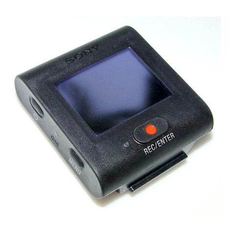
Sony BVF-55 User manual

ELECTRONIC VIEWFINDER
BVF-55
電気製品は、安全のための注意事項を守らないと、
火災や人身事故になることがあります。
このオペレーションマニュアルには、事故を防ぐための重要な注意事項と
製品の取り扱いかたを示してあります。このオペレーションマニュアルを
よくお読みのうえ、製品を安全にお使いください。お読みになったあと
は、いつでも見られるところに必ず保管してください。
OPERATION MANUAL [Japanese/English/German]
1st Edition (Revised 4)

電気製品は、安全のための注意事項を守らないと、火災や感電などにより死亡や
大けがなど人身事故につながること が あり、危険です。
事故を防ぐために次のことを 必 ず お 守りください。
安全のための注意事項を守る
2(JP)ページの注意事項をよくお読みください。
定期点検を実施する
長期間安全に使用していただくために、定期点検を実施することをおすすめしま
す。点検の内容や費用については、ソニーのサービス担当者または営業担当者
にご相 談ください。
故障したら使用を中止する
ソニーのサービス担当者、または営業担当者にご連絡ください。
万一、異常が起きたら
,1カメラの 電 源を 切る。
2接続コードを抜く。
3ソニーのサービス担当者、または営業担当者に修
理を依頼する。
警告表示の意味
このオペレーションマニュアル
および製品では、次のような表
示をしています。表示の内容を
よく理解してから本文をお読み
ください。
この表示の注意事項を守らない
と、火災や感電などにより死亡
や大けがなど人身事故につなが
ることがあります。
注意を促す記号
行為を禁止する記号
日本語
炎が出たら
•異常な音、
におい、煙
が出たら
•落下させた
ら
安全のために
,すぐにカメラの電 源を切り、消 火 する。

1(JP)
日
本
語
目次
警告 ............................................................................................................ 2(JP)
概要 ............................................................................................................... 3(JP)
各部の名称と働き ............................................................................................ 4(JP)
取り付け ........................................................................................................... 6(JP)
BVF-55の取り付けかた ..................................................................................... 6(JP)
スタジ オ 用 モ ニターフード(付属)、OB用屋外フードVFH-550(別売り)
の取り付けかた ...................................................................................... 8(JP)
ナンバープレート(付属)の取り付けかた ........................................................ 8(JP)
使いかた ........................................................................................................... 9(JP)
電源の投入 ........................................................................................................ 9(JP)
位置調整 ............................................................................................................ 9(JP)
主な仕様 ........................................................................................................ 11(JP)

2(JP)
分解しない、改造しない
分解したり、改造したりすると、感 電 の原 因となります。
ビューファインダー内部の調整や点検を行う必要がある場合は、必ずソニーのサー
ビス担当者にご依頼ください。
内部に水や異物を入れない
水や異物が入ると火災や感電の原因となります。
万一、水や異物が入ったときは、すぐにカメラの電源を切り、接続コードを 抜いて、
ソニーのサービス担当者または営業担当者にご相談ください。
油煙、湯気、湿気、ほこりの多い場所では設置・使用しない
上記のような場所で設置・使用すると、火災や感電の原因となります。
火災 感電
下記の注意を守らないと、火災や感電により
死亡や大けがにつながることがあります。

3(JP)
BVF-55は、カメラとカメラアダ プターのセットに 取り付け て 使 用 する5インチ白黒ビューファ
インダーです。
主な特長を以下に示します。
主な特長
省エネルギー設計
入力電圧の許容範囲が広く(10.5〜17V)、低消費電力(11W)です。
高解像度
高性能ブラウン管を採用し、水平解像度 650 本以上という高解像度を実現しています。
両エッジピーキング回路採用
画像の両エッジで映像信号の補正を行なうので、シャープな 画 像が 得られ、フォーカス合
わせが容易になります。
大型アップタリーランプ
点灯時、白色から赤色に変わることによって、認識性を高めた大型アップタリーラン プ を 装
備しています。
ナンバープレートが 取り付け 可 能 で、複 数カメラで の オ ペレーションに対 応します。
アップタリーランプの明るさは被写体に影響を与えないように調整することもできます。
2系統のタリーランプ
レッドタリー 、グリーンタリー 信 号 が入力されると、それぞれに対応したランプが点灯します。
優れた操作性
パンニングは左右方向にそれぞれ90度、チルティングは上下にそれぞれ40度の範囲で調
整できます。
本体は約1.9kgと軽量で、堅牢なアルミダイキャストボ ディを採用し ており、重心移動もな
いため、操作性にすぐれています。
防滴構造
JIS防滴II型対応となっております。
スタジオ用屋内フード(付属)およびOB用屋外フードVFH-550
(別売り)を取り
付け可能
堅牢で操作性のよいスタジオ用屋内フードと、遮 光性に優れているOB(Outside
Broadcasting:屋外番組制作)用屋外フード(VFH-550)を用意しています。
ワイドスクリーン機能
カメラからのコントロール信号により、アスペクト比を 1 6:9 に することが できます 。
ピーキングOFFコントロール
カメラからのコントロール信号により、ピーキングをOFFにすることができます。
概要

各部の名称と働き
4(JP)
各部の名称と働き
1G TALLY ランプ(緑)
グリーンタリー 信号が入力すると、点灯します。
2R TALLY ランプ(赤)
レッドタリー 信号が入力すると、点灯します。
3アップタリーランプ(赤)
ナンバープレート(付属)が取り付け可能です。
UPTALLYスイッチを O N に すると、RTALLYランプと同様に働き
ます。
4チルティングロックレバー
チルティングポジションを任意の位置でロックできます。
512ピンコネクター
接続ケーブル(付属)を使って、ビデオカメラのVFコネクターと接
続します。
ビデオカメラ から電源・映像信号・タリー 信 号 が入力されます。
6CONTRASTつまみ1)
画像のコントラスト(濃淡)を調整します。
7BRIGHTつまみ1)
画像の明るさを調整します。
8PEAKINGスイッチとPEAKINGつまみ1)
スイッチを O N に すると、つまみで画像の輪郭を補正することがで
きます 。
カメラによっては、スイッチ が O N の 状態でもコントロール信号によ
りピーキングを OFFにすることができます。
1)これらのつまみによる調整は、ビデオカメラの出力信号には影響ありま
せん。
1 2
4
5
3
8
6
7

5(JP)
9チルティング ノブ
スムー ズ な チ ルト動 作 に 調整できます。
0UP TALLYスイッチ
ONにすると、アップタリーラン プが RTALLYランプと同様に働き
ます。
qa UP TALLY DIMMER
アップタリーラン プ の 明 るさを 調 整し ま す 。
9
q;
qa

取り付け
6(JP)
取り付け
BVF-55の取り付けかた
カメラアダプターに取り付ける場合
1カメラアダプターからブラインドネジ(4本 )を取り外 す。
2六角レンチ(付属)と六 角ボルト(4×12、4本、付属)を使って、Vウェッジ シューアタッ
チメント(付属)をカメラアダプターに取り付ける。
3BVF-55をカメラアダプターに取り付ける。
取り付けると、カチッと音 がして 固 定されます。
ドライバーなど
ブラインドネジ

7(JP)
4カメラの 1.5インチビューファインダーを取り外 す。
取り外しか たに つ い ては 、カメラのオペレーションマニュアルをご覧ください。
5接続ケーブル(付属)を使用して、BVF-55の12ピンコネクターとビデ オカメラの V F コ
ネクターとを接続する。
BVF-55をカメラアダプターから取り外すには
レバーを引きながら、ボタンを押し て 下図のようにビューファインダーを 手前に引いて取り外
します。
12ピンコネクターへ
クランプ
接続ケーブル
ビデオカメラの
VFコネクターへ
ボタン レバー

取り付け
8(JP)
スタジオ用モニターフード(付属)、OB用屋外フードVFH-550
(別売り)の取り付けかた
OB用屋外フードVFH-550(別売り)の取り付けかたは、スタジ オ 用モニターフード(付属)
と同じです。ここで は 、スタジ オ 用 モ ニターフード(付属)の取り付けかたとして説明しま
す。
1溝に引っかけて、取り付ける。
2ねじを回して、固 定 する。
ナンバープレート(付属)の取り付けかた
ナンバープレートの 左右のつめをアップタリーラン プ の 溝 に 差し込 みます。
溝
アップタリーランプ
溝
ナンバープレート
1

9(JP)
使いかた
電源の投入
カメラアダプター の 電 源を 入れると、ビューファインダーにも電源が入ります。
電源を入れて数秒後に、画像が現れます。
BRIGHTつまみに関するご注意
BRIGHTつまみが左いっぱいになっていると、画像が出ないことがありますのでご注意く
ださい。
位置調整
ビューファインダーの位置を以下のように調整して、お使いください。
パンニング調整
正面をセンターとし て 左 右 に90度ずつ動かすことができます。
180度

取り付け
10(JP)
チルティング調整
1チルティングロックレバーをフリクション(可動)の位置にする。
2チルティングノブを回して、スムーズなチルト動 作 を 決 める。
3チルティング角度を調整する。
チルティング角度を固定するときは、チルティングロックレバーをロック(固定)の位置
にする。
フリクション(可動)
の位置 チルティング
ロックレバー
ロック(固定)の位置
チルティング ノブ
40度
ゆるむ 40度

11(JP)
主な仕様
ブラウン管 5 型モノクローム
有効画面寸法 4:3モード 97×73mm(幅×高さ)
16:9 モード 97×54.56mm(幅×高さ)
信号方式 EIA標準
走査 2:1インターレース、525本
5%アンダースキャン
水平リニアリティ 8%以下
垂直リニアリティ 7%以下(4:3 モード)
解像度 650本以上(中心)、550本以上(周辺)
入力端子 12ピンコネクター
映像入力:1Vp-p、同期負、3kΩ
画面歪 3%以下
周波数特性 −3dB(8MHz)以内
電源 DC10.5V〜 17V、定格 12V
消費電力 11W
動作周囲温度 −10℃〜+45℃
動作周囲湿度 0〜90%
結露しないこと
動作高度 3000m以下
重量 本体:約2.3kg(フードを 含 む )
付属品 Vウェッジ シューアタッチメント(1)
ねじ(4)
六角レンチ(1)
接続ケーブル(1)
スタジ オ 用モニターフード(1)
ナンバープレート(1)
六角穴付きボルト(4)
オペレーションマニュアル(1)
ガラス筒型ヒューズ(1)
単位:mm
外形寸法図
仕様および外観は、改良のため予告なく変更することがあります
が、ご了承ください。
191
188
6
156
291

For the customers in U.S.A.
This equipment has been tested and found to comply with
the limits for a Class A digital device, pursuant to Part 15 of
the FCC Rules. These limits are designed to provide
reasonable protection against harmful interference when the
equipment is operated in a commercial environment. This
equipment generates, uses, and can radiate radio frequency
energy and, if not installed and used in accordance with the
instruction manual, may cause harmful interference to radio
communications. Operation of this equipment in a residential
area is likely to cause harmful interference in which case the
user will be required to correct the interference at his or her
own expense.
You are cautioned that any changes or modifications not
expressly approved in this manual could void your authority
to operate this equipment.
The shielded interface cable recommended in this manual
must be used with this equipment in order to comply with the
limits for a digital device pursuant to Subpart B of Part 15 of
FCC Rules.
For the customers in Europe
This product with the CE marking complies with the EMC
Directive(89/336/EEC) issued by the Commission of the
European Community.
Compliance with this directive implies conformity to the
following European standards:
•EN55103-1: Electromagnetic Interference(Emission)
•EN55103-2: Electromagnetic Susceptibility(Immunity)
This product is intended for use in the following
Electromagnetic Environment(s):
E1 (residential), E2 (commercial and light industrial),
E3 (urban outdoors) and E4 (controlled EMC environment,
ex. TV studio)
Pour les clients européens
Ce produit portant la marque CE est conforme à la Directive
sur la compatibilité électromagnétique (EMC) (89/336/CEE)
émises par la Commission de la Communauté européenne.
La conformité à cette directive implique la conformité aux
normes européennes suivantes:
•EN55103-1: Interférences électromagnétiques (émission)
•EN55103-2: Sensibilité électromagnétique (immunité)
Ce produit est prévu pour être utilisé dans les
environnements électromagnétiques suivants:
E1 (résidentiel), E2 (commercial et industrie légère),
E3 (urbain extérieur) et E4 (environnement EMC contrôlé ex.
studio de télévision).
English

1(GB)
English
Overview ............................................................................................ 2(GB)
Functions of parts and controls ....................................................... 3(GB)
Attaching accessories........................................................................ 5(GB)
Attaching the BVF-55 ................................................................. 5(GB)
Attaching the supplied studio monitor hood or the VFH-550 optional
OB hood ............................................................................ 7(GB)
Attaching the supplied number plate ........................................... 7(GB)
How to use the BVF-55..................................................................... 8(GB)
Turning on the BVF-55 ............................................................... 8(GB)
Adjusting the viewfinder position ............................................... 8(GB)
Specifications................................................................................... 10(GB)
Table of Contents

Overview
2(GB)
The BVF-55 electronic viewfinder is a 5-inch monochrome electronic
viewfinder designed for attachment to a video camera with the camera
adapter.
The main features are as shown below.
Main features
Low power consumption
Wide voltage range of 10.5 to 17 V.
Low power consumption (approx. 11 W).
High resolution
High-resolution picture tube, with horizontal resolution of over 650 lines.
Phase-corrected peaking circuit (for both side edges)
Adoption of the peaking circuit ensures sharp pictures and thus make
forcussing easier.
Large up-tally lamp
The up-tally lamp is large and easier to see by switching from white to red.
The up-tally lamp with the supplied number plate attached can be used for
the multi-camera operations.
You can adjust the lamp brightness.
Two tally system
Each lamp lights corresponding to whether a red tally or green tally signal
is input.
Superior operation
Panning up to 90 degrees left and right is possible.
Tilting 40 degrees up and down is also possible.
Because the BVF-55 is light (approx. 1.9 kg) and features a strong
aluminum diecast and water-resist body, it has no movement of the weight
center and offers superior operations.
Supplied studio monitor hood and VFH-550 optional OB hood
The supplied studio monitor hood is strong and easy to use.
The VFH-550 offers superior shading character.
Wide-screen function
The aspect ratio of 16:9 is available with a control signal from the camera.
Peaking OFF control
A control signal from the camera will turn off the peaking control.
Overview

3(GB)
Functions of parts and controls
1G TALLY lamp (green)
Lights when the green tally signal is input.
2R TALLY lamp (red)
Lights when the red tally signal is input.
3Up-tally lamp (red)
Set UP TALLY switch to ON. The lamp lights in the
same way as the R tally lamp.
The supplied number plate can be attached to this.
4Tilt lock lever
Fixes any tilting position.
512-pin connector
Connects to a video camera’s VF connector, using the
supplied connecting cable.
Power and video/tally signals are supplied through this
connector.
6CONTRAST knob1)
Adjusts the contrast of the viewfinder picture.
7BRIGHT knob1)
Adjusts the brightness of the viewfinder picture.
8PEAKING switch and knob1)
Setting this switch to ON and turning the knob corrects
viewfinder image.
Used to adjust the focus on the video camera.
Depending on the camera to be used with the BVF-55,
the peaking control can be turned off by a control
signal sent from the camera even if the PEAKING
switch is set to ON.
1) These controls do not affect the output signal of the video
camera.
1 2
4
5
3
8
6
7

Functions of parts and controls
4(GB)
9Tilt knob
Adjusts the tilt friction.
0UP TALLY switch
When this switch is set to ON, the UP TALLY lamp
lights in the same way as the R tally lamp.
qa UP TALLY DIMMER control
Adjusts the brightness of the UP TALLY lamp.
9
q;
qa

5(GB)
Attaching accessories
Attaching the BVF-55
Attaching to the camera adaptor
1Remove the four decorative screws from the camera adaptor.
2Attach the supplied V-wedge shoe attachment to the camera adaptor
using the supplied hexagonal wrench and four hexagonal screws (4 ×
12).
3Slide the BVF-55 forward along the V-wedge shoe attachment until it
cliks and is fixed.
Screwdriver etc.
Decorative screw

Attaching accessories
6(GB)
4Detach the 1.5-inch viewfinder from the camera.
For the detaching, refer to the operation manual of the camera.
5Connect the 12-pin connector to the video camera’s VF connector
using the supplied connecting cable.
To detach the BVF-55 from the camera adaptor
To detach the BVF-55, pull the lever and push down the button while
pulling the viewfinder towards you, as shown in the figure below.
To 12-pin connector Connecting cable
Clamp
To video camera’s
VF connector
Button Lever
Table of contents
Languages:
Other Sony Camera Accessories manuals

Sony
Sony IPT-DS1 - Party-shot Digital Camera Docking... User manual

Sony
Sony BVF-20W User manual

Sony
Sony VF-72CPK User manual

Sony
Sony XCD-V50CR User manual

Sony
Sony HDVF-9900 User manual

Sony
Sony E01X23A41 User manual

Sony
Sony DKA-GP30 User manual

Sony
Sony APK-THAB Operating Instructions -... User manual

Sony
Sony Cyber-shot DSC-F707 User manual

Sony
Sony XLR-H1 User manual