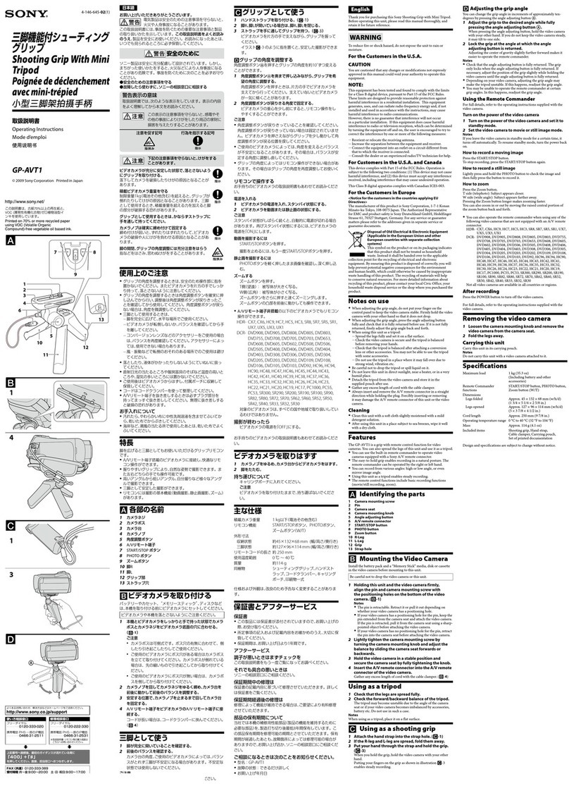
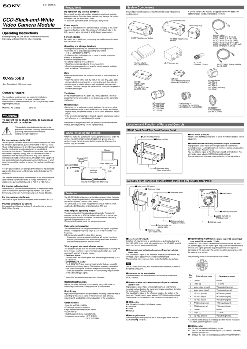
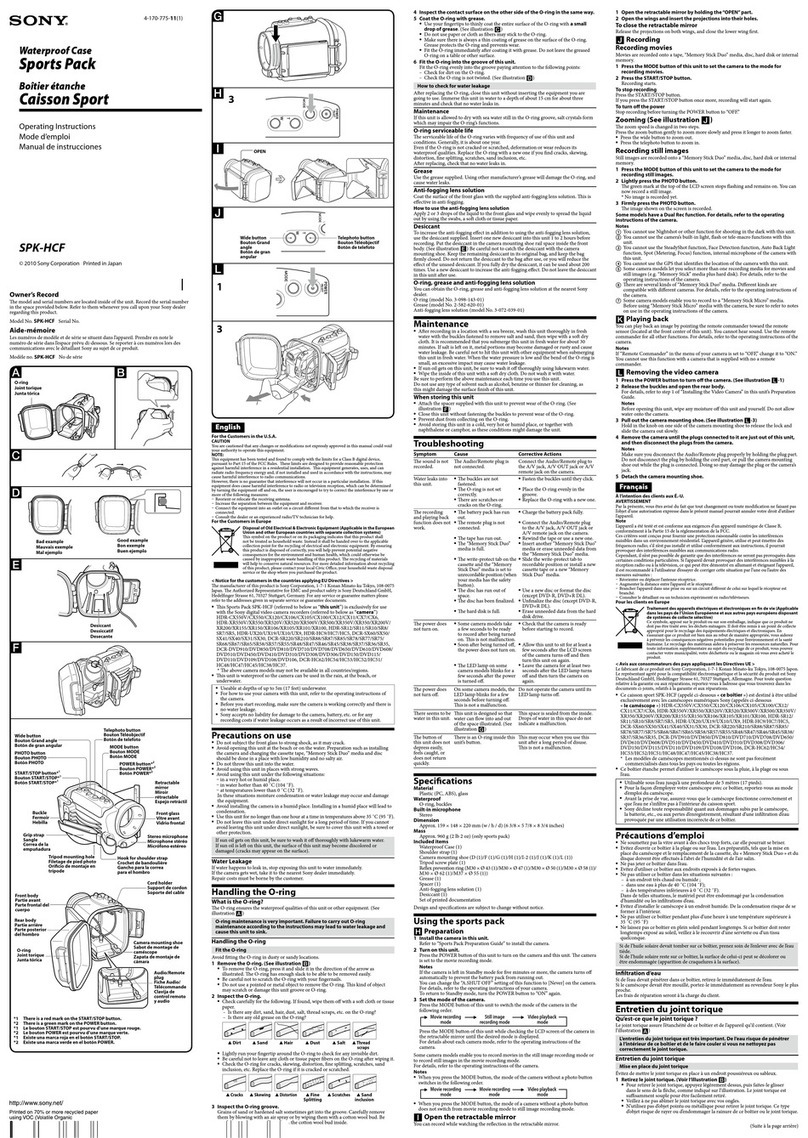
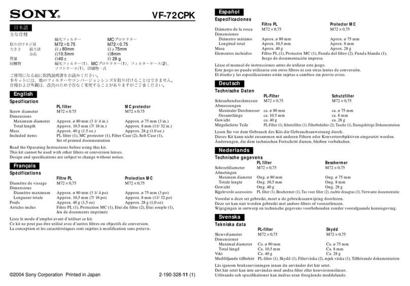
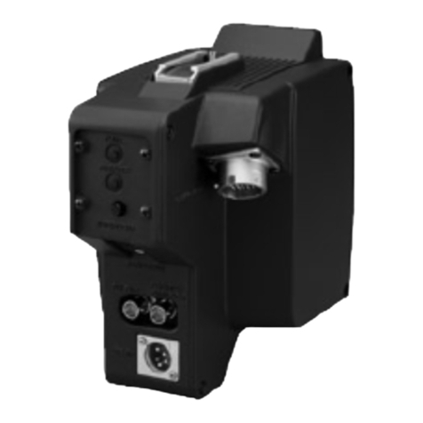
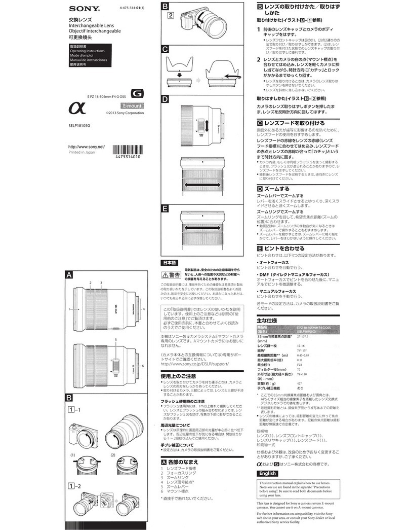
Sony DVF-L350 User manual

LCD Color View Finder
4-459-184-11 (1)
© 2013 Sony Corporation
Operating Instructions
Before operating the unit, please read this manual thoroughly
and retain it for future reference.
DVF-L350

Table of Contents
2
Table of Contents
Overview ......................................................3
Usage Notes.................................................3
Parts Identification......................................4
Attaching the Viewfinder to a Camera.......5
Detaching the Viewfinder ..........................5
Adjusting the Position ................................6
Adjusting the Left/Right Position ...............6
Adjusting the Forward/Backward Position
and Height .......................................6
Adjusting the Angle ..................................7
Raising the VF Barrel and Eyepiece ..........7
Raising the VF Barrel................................7
Removing the VF Barrel ............................8
Cleaning the LCD Screen ...........................8
Specifications..............................................9

Overview / Usage Notes 3
Overview
The DVF-L350 is a 3.5-inch color LCD viewfinder.
This unit has the following features.
High resolution and wide visual angle
The viewfinder uses a high-resolution LCD for a
resolution of 960 × 540.
The large LCD allows you to shoot with ease when the
eyepiece is removed.
Stable picture
The LCD screen provides stable images without
distortion, regardless of display’s brightness.
High-performance loupe
The 2-group 3-element lens (including aspheric lens)
produces pictures with low distortion while allowing
adjustment over a wide range of visibility.
Adjustable, removable eyepiece and VF barrel
Raising or removing the eyepiece allows you to shoot
while viewing the viewfinder screen from a distance.
Raising or removing the VF barrel allows you to work
while viewing the LCD screen directly.
Usage Notes
Place of use
When using the viewfinder in low temperature
environments, dynamic resolution levels may decrease
during the period immediately after you turn on the
power.
Condensation
If the unit is suddenly taken from a cold to a warm
location, or if ambient temperature suddenly rises,
moisture may form on the outer surface of the unit and/or
inside of the unit. This is known as condensation. If
condensation occurs, turn off the unit and wait until the
condensation clears before operating the unit. Operating
the unit while condensation is present may damage the
unit.
LCD panel
The LCD panel fitted to this unit is manufactured with
high precision technology, giving a functioning pixel
ratio of at least 99.99%. Thus a very small proportion of
pixels may be “stuck”, either always off (black), always
on (red, green, or blue), or flashing. In addition, over a
long period of use, because of the physical characteristics
of the liquid crystal display, such “stuck” pixels may
appear spontaneously. These problems are not a
malfunction.
LCD image display
Due the physical characteristics of LCD panels, there may
be a decrease in brightness or change in color temperature
over a long period of use. These problems are not a
malfunction.
In addition, these occurrences will not affect recorded
data.
Viewfinder lens
Do not leave the viewfinder lens facing toward a strong
light source, such as sunlight.
Burnout of the LCD panel or fire may occur if the lens
focuses the sunlight or other strong light source.
Maintenance
• Use a dust blower to remove dust from the screen.
• Do not use solvents such as thinner to clean the screen.
Parts Identification
4
Parts Identification
aViewfinder connector
Connect this to the VF connector on the camera.
bViewfinder cable
cEyecup
dDiopter adjuster
Turn the adjuster to adjust the diopter so that the image is
clearly visible.
eEyepiece
Raise or remove this according to the situation.
fViewfinder barrel
Raise or remove this according to the situation.
gTally indicator
This is located at the top of the unit’s internal LCD screen.
This lights or blinks red or turns off according to the
situation.
Lit: The camera/camcorder is recording.
Blinking: An error or warning has occurred.
For details on the status of the indicator, refer to the
operating instructions for your camera/camcorder.
hFOCUS MAG (magnified display) button
Magnifies the height and width of the image (x2) for
easier focus adjustment. This does not affect the camera’s
output signal.
The display switches between magnified display and
normal display with each press of the button.
iMIRROR switch
Inverts the right and left of the image.
Set this to ON when viewing the image with the VF barrel
and eyepiece removed.
ON: Inverts the right and left of the image.
OFF: The image is not inverted.
jCONTRAST adjustment knob
Turn the knob to adjust the contrast on the screen. This
does not affect the camera’s output signal.
kRotation arm
Rotate the arm to adjust the position of the unit.
lArm lock knob
Use this when adjusting the forward/backward position
and height of the unit.
mL-arm
Attach this to the viewfinder shoe of the camera.
You can also slide the unit forward, backward, left, and
right to adjust its position.
nSlide stopper
Prevents this unit from detaching from the camera when
sliding it left and right.
1
q
f
qd
qs
qa
0
9
8
7
2
3
5
4
6

Attaching the Viewfinder to a Camera 5
Attaching the Viewfinder
to a Camera
Do not leave the eyepiece lens facing toward the sun
when the viewfinder is attached.
Direct sunlight may enter and focus within the eyepiece
lens, resulting in fire.
1
Attach the viewfinder to the camera.
1Loosen the fixing ring on the camera’s viewfinder
shoe.
2Align the groove in the viewfinder’s L-arm with
the viewfinder shoe, and attach the viewfinder by
sliding it horizontally.
The slide stopper lowers automatically.
3Tighten the fixing ring.
2
Connect the cable.
1Connect the viewfinder connector to the VF
connector on the camera.
Verify the orientation of the connector, and insert
it until it clicks into place.
2Secure the cable with the clamp if necessary.
• Always turn off the camera before connecting the
viewfinder connector to the VF connector on the
camera. If you make the connection while the
camera is on, the viewfinder may not function
properly.
• Be sure to check the shape of the viewfinder
connector, and insert it in the proper orientation.
• Fully insert the viewfinder connector into the
camera’s VF connector and make sure it is secure.
If the connector is not firmly connected, the image
may be distorted and the tally indicator may not
light properly.
Detaching the Viewfinder
1
Remove the viewfinder cable from the clamp, and
disconnect the connector from the camera’s VF
connector.
Pull the connector straight out while pressing the lock
release buttons on both sides of the connector.
Forcibly pulling the connector without pressing the
lock release buttons may damage the connector.
2
Loosen the fixing ring on the camera’s viewfinder
shoe.
3
Slide the viewfinder in the opposite direction from
when you attached it, and raise the slide stopper to
detach the viewfinder.
CAUTION
1
23
Slide stopper
Clamps
VF connector
Notes
Note

Adjusting the Position
6
Adjusting the Position
Rotating the viewfinder too much in a single direction
while adjusting its position and angle may pull the
viewfinder cable and result in disconnection.
Adjusting the Left/Right Position
Loosen the fixing ring on the camera’s viewfinder shoe,
and slide the viewfinder left or right to adjust its position.
When you finish adjustment, tighten the fixing ring to
secure the position.
Adjusting the Forward/Backward
Position and Height
Turn the viewfinder’s arm lock knob in the opposite
direction of LOCK, then slide the viewfinder forward or
backward and rotate the rotation arm to adjust its position.
When you finish adjustment, turn the arm lock knob in the
LOCK direction.
Note
Fixing ring
Arm lock knob

Raising the VF Barrel and Eyepiece 7
Adjusting the Angle
Hold the viewfinder and adjust its angle.
Raising the VF Barrel and
Eyepiece
You can view the LCD screen inside the viewfinder or its
mirror image by raising the VF barrel or eyepiece.
This section describes how to raise or remove the VF
barrel. The eyepiece can be raised or removed in the same
way.
When viewing the LCD screen directly, set the MIRROR
switch to ON.
Raising the VF Barrel
1
Press the bottom latch to release it.
Note
LCD screen
1
2

Cleaning the LCD Screen
8
2
Raise the VF barrel.
The VF barrel locks at 120 degrees.
Use the viewfinder in this lock position under normal
circumstances.
You can also open the VF barrel beyond this lock
position. To return to the 120-degree lock position after
doing so, close the VF barrel to its closed position before
opening it again.
Removing the VF Barrel
1
Press the bottom latch to release it.
2
Raise the VF barrel.
3
Slide the top button in the opposite direction of the
VF barrel to release the lock.
4
Slide the VF barrel horizontally to remove it.
Cleaning the LCD Screen
When cleaning the viewfinder’s LCD screen, remove the
viewfinder from the camera, and take care not to damage
the components.
For details on how to remove the viewfinder from the
camera, see “Detaching the Viewfinder” (page 5).
For details on how to remove the VF barrel, see
“Removing the VF Barrel” (page 8).
Removing dust from the surface of the LCD screen
Use a dust blower.
Do not use thinner or other solvents.
After use in harsh environments
Be sure to perform the following maintenance after using
the viewfinder at dusty locations, beaches, hot springs, or
other harsh environments.
• Use an airbrush to carefully remove any dust or sand
from inside the viewfinder.
• Clean the contacts of the connectors.
• After performing the above maintenance, perform a
basic operation test and check that the viewfinder is
functioning properly.
4
1
3
2
Note

Specifications 9
Specifications
General
LCD
Performance
Connector
Supplied accessories
Related accessories
Design and specifications are subject to change without
notice.
Power supply
10.5 V to 17.0 V DC (supplied from the camera)
Power consumption
1.2 W
Operating temperature
0 °C to 40 °C (32 °F to 104 °F)
Storage temperature
–20 °C to +60 °C (–4 °F to +140 °F)
Mass
Approx. 660 g (1 lb 7.3 oz)
Dimensions
3.5-inch color TFT transmissive LCD
Display area
76.8 × 43.2 mm (3 1/8× 1 3/4inches) (H/V, 16:9
aspect ratio)
Brightness
300 cd/m2(peak brightness, typical)
Resolution
960 × 540
Color temperature
D65
Rectangular 26-pin connector (1)
Before Using this Unit (1)
Operating Instructions (CD-ROM) (1)
Warranty (1)
Solid-State Memory Camcorder
PMW-F5, PMW-F55
Unit: mm (inches)
87 (31/2)
215 (8 1/2)
242 (9 5/8)
Notes
• Always verify that the unit is operating properly
before use. SONY WILL NOT BE LIABLE FOR
DAMAGES OF ANY KIND INCLUDING, BUT
NOT LIMITED TO, COMPENSATION OR
REIMBURSEMENT ON ACCOUNT OF THE
LOSS OF PRESENT OR PROSPECTIVE PROFITS
DUE TO FAILURE OF THIS UNIT, EITHER
DURING THE WARRANTY PERIOD OR AFTER
EXPIRATION OF THE WARRANTY, OR FOR
ANY OTHER REASON WHATSOEVER.
• SONY WILL NOT BE LIABLE FOR CLAIMS OF
ANY KIND MADE BY USERS OF THIS UNIT OR
MADE BY THIRD PARTIES.
• SONY WILL NOT BE LIABLE FOR THE
TERMINATION OR DISCONTINUATION OF
ANY SERVICES RELATED TO THIS UNIT THAT
MAY RESULT DUE TO CIRCUMSTANCES OF
ANY KIND.

Sony Corporation
Table of contents
Other Sony Camera Accessories manuals

Sony
Sony VCT-670-RM User manual

Sony
Sony LSF-S58 User manual

Sony
Sony HD Super Motion HKCU1001 User manual

Sony
Sony MPK-DVF O User manual

Sony
Sony XCD-V50 User manual

Sony
Sony CA-D50 User manual

Sony
Sony XC-ES50 User manual

Sony
Sony HDLA1500 User manual

Sony
Sony HDVF-550 User manual

Sony
Sony DXF-20W User manual

Sony
Sony VF-72CPK User manual

Sony
Sony HDVF-9900 User manual

Sony
Sony LSF-VHA User manual

Sony
Sony MPK-THC O-ring User manual

Sony
Sony VF-R25NK User manual

Sony
Sony LCR-VX2000 User manual

Sony
Sony SH-L35W User manual

Sony
Sony VAIO VGP-BPS22A User manual

Sony
Sony ACC-CN3BC User manual

Sony
Sony VCT-FS7 User manual