4
HCD-DZ300 SECTION 1
SERVICING NOTE
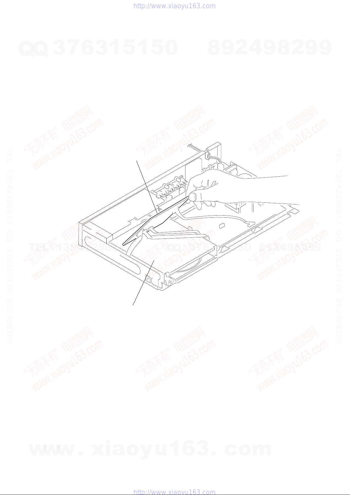
NOTES ON HANDLINGTHE OPTICAL PICK-UP BLOCK
OR BASE UNIT
The laser diode in the optical pick-up block may suffer electrostatic
break-down because of the potential difference generated by the
charged electrostatic load, etc. on clothing and the human body.
During repair, pay attention to electrostatic break-down and also
use the procedure in the printed matter which is included in the
repair parts.
The flexible board is easily damaged and should be handled with
care.
NOTES ON LASER DIODE EMISSION CHECK
The laser beam on this model is concentrated so as to be focused on
the disc reflective surface by the objective lens in the optical pick-
up block. Therefore, when checking the laser diode emission,
observe from more than 30 cm away from the objective lens.
LASER DIODE AND FOCUS SEARCH OPERATION
CHECK
Carry out the“S curve check”in “CD sectionadjustment” and check
that the S curve waveform is output several times.
DISC SLOT LOCK
The disc slot lock function for the antitheft of an demonstration
disc in the store is equipped.
Setting Procedure :
1. Press the ?/1 button to turn the set on.
2. Press the [FUNCTION] button to set DVD function.
3. Insert a disc.
4. Press the x stick and the A button simultaneously for five
seconds.
5. The message “LOCKED” is displayed and the slot is locked.
Releasing Procedure :
1. Press the x stick and the A button simultaneously for five
seconds again.
2. The message “UNLOCKED” is displayed and the slot is
unlocked.
Note: When “LOCKED” is displayed, the slot lock is not released by
turning power on/off with the ?/1 button.
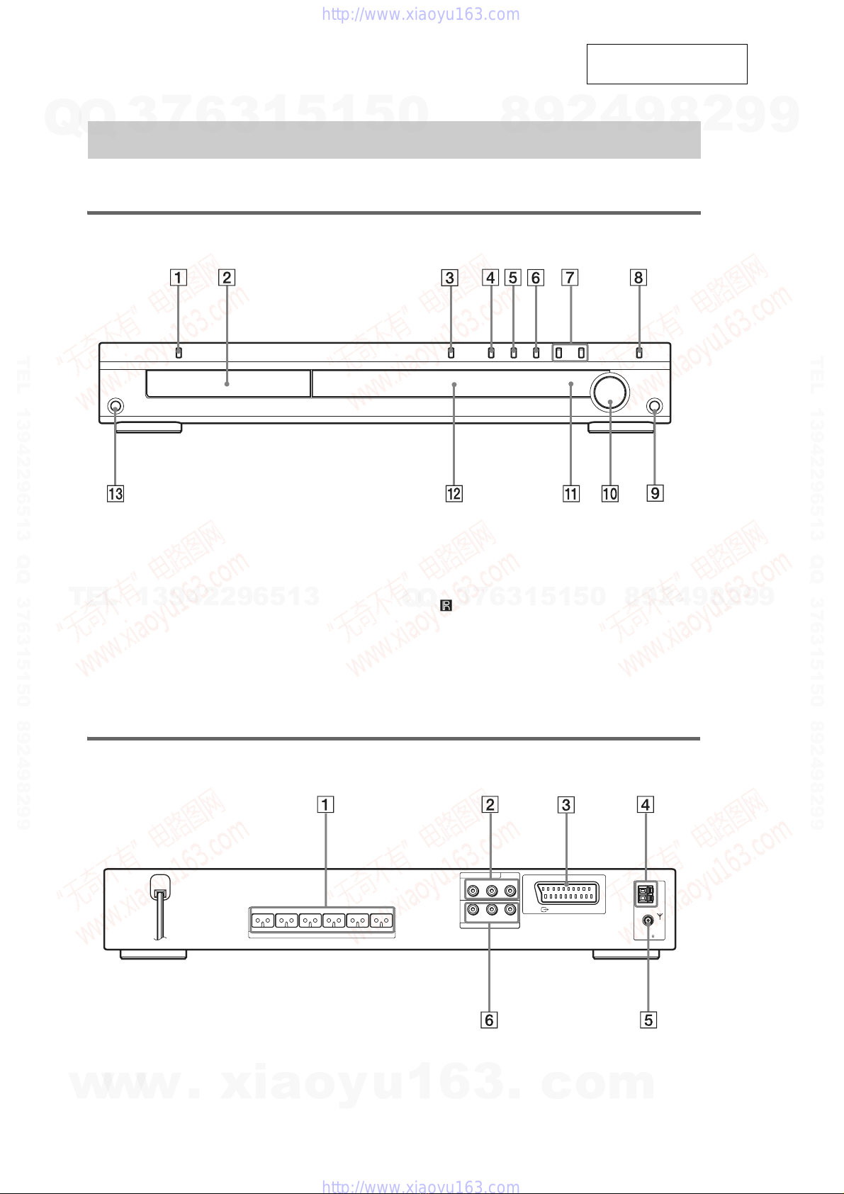
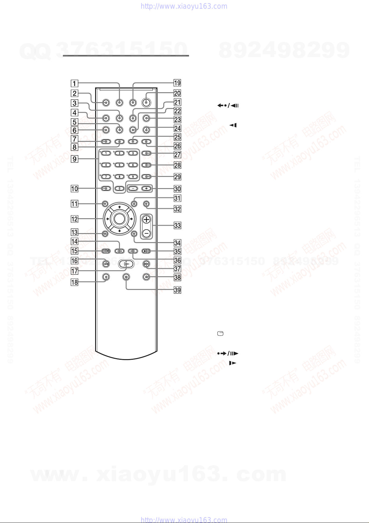
Note 1: Regarding the notification symbol “R”
Because the number of the operating buttons of this product are
limited, some operations require use of the operating buttons of
the remote commander, When a specific operation requires use
of the operating buttons of the remote commander, “R” is added
to the specific operating procedure in this manual.
Example MENU/NO “R” The MENU/NO button of remote
commander.
Note 2: Incorrect operations may be performed if the test mode ia not
entered properly.
In this case, press the ?/1 button to turn the power off, and
retry to enter the test mode.
Note 3: If the disc tray does not open and the message “LOCKED”
appears, press the x stick and the Abutton simultaneously
for seconds or longer.
Then remove your fingers from the above stick and the button.
The message “UNLOCKED” appears for 2 seconds and the disc
tray opens.
Note on DMB10 board replacement
When the self-diagnosis function is activated to
prevent the system from malfunctioning, a 5-
character service number (e.g., C 13 50) with a
combination of a letter and 4 digits appears on
the screen and the front panel display. In this
case, check the following table.
Self-diagnosis Function
(When letters/numbers appear in the
display)
First 3
characters of
the service
number
Cause and/or corrective action
C 13 The disc is dirty.
,Clean the disc with a soft cloth
(page 81).
C 31 The disc is not inserted correctly.
,Restartthe system, thenre-insert
the disc correctly.
E XX
(xx is a number) To prevent a malfunction, the
system has performed the self-
diagnosis function.
,Contact your nearest Sony
dealer or local authorized Sony
service facility and give the 5-
character service number.
Example: E 61 10
C:13:50
New part of EEP ROM (IC103) on the DMB10 board cannot
be used. Therefore, if the mounted DMB10 board
(A-1088-453-A) is replaced, exchange new EEP ROM (IC103)
with that used before the replacement.
w
w
w
.
x
i
a
o
y
u
1
6
3
.
c
o
m
Q
Q
3
7
6
3
1
5
1
5
0
9
9
2
8
9
4
2
9
8
T
E
L
1
3
9
4
2
2
9
6
5
1
3
9
9
2
8
9
4
2
9
8
0
5
1
5
1
3
6
7
3
Q
Q
TEL 13942296513 QQ 376315150 892498299
TEL 13942296513 QQ 376315150 892498299
http://www.xiaoyu163.com
http://www.xiaoyu163.com