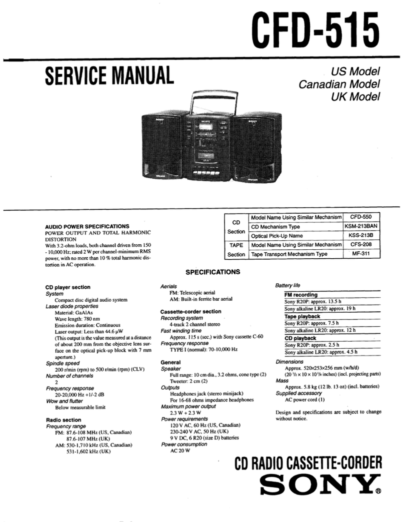
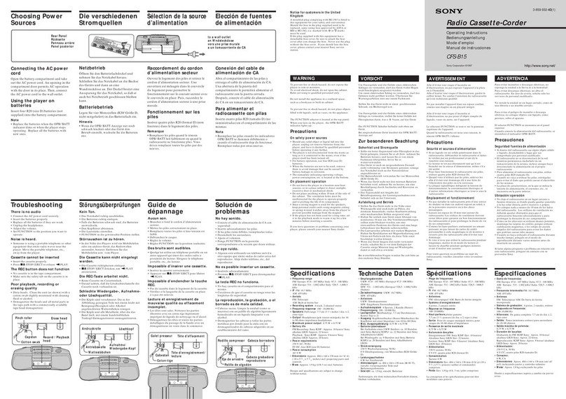
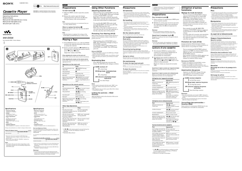
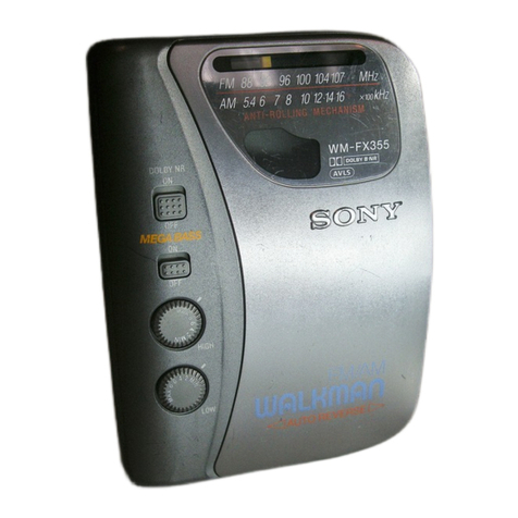
Sony TC-158SD User manual

SPECIFICATIONS
Power
Requirements:
AC
120V
60Hz
(US,
Canadian
model)
AC
110,
120,
220
or
240V—50/60
Hz
(AEP,
E
model)
DC
6V
four
batteries
of
size
D
(IEC
designation
R20)
Sony
Rechargeable
Battery
Pack
BP-8H
(optional)
US
Model
Canadian
Model
AEP
Mode!
E.
Model
STEREO
CASSETTE-CORDER
Fast
Forward
and
Rewind
Time:
Approx.
90
sec.
(C-60,
at
6V)
Recording
System:
4-track
2-channel
stereo
Speaker:
10cm
(4
inches)
dia.
Power
Output:
700
mw
Bias
Frequency:
105
kHz
12V
car
battery
with
Sony
Car
Battery
Signal-to-noise
Ratio:
DOLBY
NR
OFF
Cord
DCC-129
(optional)
Power
Consumption:
12W
Dimensions:
Approx.
350
(w)
x
100
(h)
x
240
(d}
mm
133/4
(w)
x
4
(h)
x
93/g
(d)
inches
including
projecting
parts
and
controls
Weight:
Approx.
4.8kg,
10
lb
9
0z
with
batteries
*‘Dolby’
and
the
double-D
symbol
are
the
trade
marks
of
Dalby
Laboratory
Inc.
Noise
reduction
system
manufac-
tured
under
license
from
Doiby
Laboratory
Inc.
“0dB
=0.775V
SAFETY-RELATED
COMPONENT
WARNING!!
COMPONENTS
IDENTIFIED
BY
SHADING
ON
THE
SCHEMATIC
DIAGRAMS
AND
IN
THE
PARTS
LIST
ARE.
CRITICAL
TO
SAFE
OPERATION.
REPLACE
THESE:
COMPONENTS
WITH
SONY
PARTS
WHOSE
PART
NUMBERS
APPEAR
AS
SHOWN
IN
THIS
MANUAL
OR
IN
SUPPLEMENTS
PUBLISHED
BY
SONY.
With
Ferri-Chrome
Cassette
59
dB
at
peak
level
(NAB)
57
dB
(DIN,
1975
rev.)
49
dB
(DIN,
old)
With
chromium
dioxide
cassette
55
dB
at
peak
level
(NAB)
DOLBY
NR
ON
Improved
by
5dB
at
1kHz,
10dB
above
SkHz
Total
Harmonic
Distortion:
1.3%
*
Contistued
on
—
2-
>
CUATION
OF
VOLTAGE
SELECTOR
SETTING
“When
changing
a
voltage
of
the
voltage
selector,
be
“sure
to
c
the
ac
power
cord.
a
i)
5O
SERVICE
MANUAL

Cetin
TC:158SD
Frequency
Response:
DOLBY
NR
OFF
Record/playback
With
Ferri-Chrome
Cassette
and
Connector:
Input
impedance
fess
than
10k
ohms
chromium
dioxide
cassette
(AEP,
E
model)
Output
impedance
less
than
10k
ohms
20—16,000
Hz
(NAB)
30—15,000
Hz
+3dB
(NAB)
30—
15,000
Hz
(DIN)
With
regular
cassette
20—14,000
Hz
(NAB)
30—
12,000
Hz
(DIN)
Wow
and
Flutter:
0.08%
WRMS
(NAB)
+0.2%
(DIN)
Inputs:
MIC
(phone
jack)
..............
2
sensitivity
0.2
mV
(~72
dB)
for
a
low-impedance
microphone
LINE
IN
(phono
jack)
......-...
2
sensitivity
0.06V
(~22
dB)
input
impedance
100k
ohms
Battery
Life:
Continuous
recording
time
Approx.
4.5
hours
with
Sony
Long-life
Batteries
size
D
Approx.
10
hours
with
Eveready
Alkaline
Batteries
No.
E95
Outputs:
LINE
OUT
(phono
jack)
........
2
output
level
0.435V
(-5
dB)
at
load
impedance
100k
ohms
suitable
load
impedance
more
than
10k
ohms
HEADPHONES
............-45
1
a
suitable
load
impedance
8—32
ohms
MODEL
IDENTIFICATION
—
Specification
Label
—
US
model
Canadian
model
SONY.
SONY.
TAPECORDER
TC-158SD
|
a
AC
120V
60Hz
l2W
DC
6V
FLASH-
TAPECORDER
TC
-
(158SD
LIGHT
BATT
SIZE
“D’X4
OR
EQUIVALENT
AC
120V
60Hz
I2W
DC
6V
FLASH-
NO.
|
LIGHT
BATT
SIZE
“Dx4
OR
EQUIVALENT
MADE
IN
JAPAN
3+
549
-
157-00
MADE
IN
JAPAN
3-
549
-
158-00
>SEP,
E
model
SONTY.
TAPECORDER
TC-158
30
AC
110,120,
220,240V
~
50/60Hz
I2w
DC 6V
==
FLASHLIGHT
BATTERY
(SIZE
“D’)x4
OR
EQUIV.
NO.
.
X
MADE
IN
JAPAN
y
3-
549-160
-00
.
’

TC-1585
SECTION
1
BLOCK
DIAGRAM
(AS1-)-@
(ASI)
+8
S-Is
u31N3ANOD
90-30
£1S‘
210
yOLVENoIY
«»—3I6
SIS‘
bISO
10S1L
I
eile!
Wha,
3AtNQ
LHOI
‘
HM
H8-d8
AY3L1V8
>
d01S
dgo
"IS
FIGVIONVHIIY
|
;
!
29€-SE143
AD
SOdb
pl
340
617
WaH)
Live
\
oe
cee
Yes
ais
(AGuaw
aavawog
|
19349
Live)
NOHLYNOIS3O
931)
e
ONIWIL
b-€S
ts
ania
uy
3Z1S
de
yOOEI-
JNO
suditve
L_,
T3
GNIM3Y
9S0
svia
10244
NO{OYYMYOS
1S¥J]
HOLOW
21S
Y
‘5
OuVMHOS
[30]
eos
UBL3W
NA
i.
20sr
(7300W
3‘d3¥)
Q3SS3ud
JUV
a753a
SNOLLNG
NOLLINAS
N3HM
:
NO,
b
a
ONILAW
GIS
[2
l
POITND
2010
19-24
TWWYON
Pag
234
(oa]!-as
ozi0
9IS‘1S~80S0
6110
|
ad/934
b'IS
ONILOW
3AINO
ONILAIW
ONILOW
Paty
Qd
HO-¥
:
t
an
1-bS
a
£0€0
f
he
we't)
é
10S~£0S0
ONIHOLIMS
934
.
Ww2096
-Sbiid
dS
diy
U3Mod
,
20£
"1060
dios
Oll~
2010
9010
SOI
bO10
Ih
M
dWv
03
Fo?
;
dwy
ua4sng
UN
Agi0a
dWv
4344n@
div
BN
re
bIFAML
X2VBAV
Id
ee
JON
Ay
e-is}o3y
BAN
TTIGOW
NvIGvNY2‘Sn)
IW
O34
V3AR1
OVAAW
Id
(1300W
3'day)
94/238
SINOHAOVIN
bls
auoo34
vim
©
6
GuyM4OS
A
peas
41no
ant
|
@
laf
jo1
ain
_
=
seeds
po
|
810
Z0iND
430
dO1S
;
:
=
dW
MALIN
+4
ONIWIL
1-€S
dWY
IW
=
:
uu
ane
3NOHdOV3H
NO
;
res
i
a
£010
aad
2010
aS
A>
HO
1o3973s
inami
HOY
y3LiWn
ZHA6!
ee
Hates
La
£-Ss
ON‘
SHO
.
dW
Y313W
WOVEAV
Id
|
Bd
1013W
ayooau
:
934
Y3130
NA
ae
aa

TC-158SD
|
Cassette
Lid
Removal
(1),
@)
and
Replacement
(@,
@)
REC/PB
connector
(AEP
model]
SECTION
2
DISASSEMBLY
Lower
Case
Removal
(1)
82.6x8
(black)
@)
lower
case
2.6x8
(black)
~~
a
‘
ee,
=
3
—
Control
Panel
Removal
3)
Press
the
PAUSE
button.
PEAK
level
indicator
O
a
;
@)
control
panel
Sep
B2.6x8
(black)
REC
LEVEL
knobs
Note:
When
replacing
the
control
panel,
take
care
of
the
PEAK
level
indicator
position.

|
TC-1588
Recorder
Mechanism
Lifting
Upper
Case
Removal
@
B3x8
{black}
QD)
battery
lid
Fal
@)
P26x8
(black)
@)
K26x10
(lower
screw
only}
K2.6x10
(lower
screw
only}

-
TC-158SD

fy
|
TC-158
SECTION
3
ADJUSTMENTS
FREES
ON
Pause
Timing
Adjustment
Clean
the
following
parts
with
a
denatured-
alcohol-moistened
swab:
—
Playback
mode
—
1.
The
take-up
reel
spindle
flange
should
touch
record/playback
head
pinch
roller
the
tension
pulley.
erase
head
rubber
belts
capstan
idlers
2.
Slowly
press
PAUSE
button.
First,
the
pinch
roller
should
release
from
the
capstan.
Next,
the
tension
pulley
should
release
from
the
take-
up
reel
spindle
flange.
Under
this
condition,
Do
not
use
a
magnetized
screwdriver
for
the
adjust
the
position
of
the
pinch
roller
by
adjustments.
bending
the
specified
parts.
Demagnetize
the
record/playback
head
with
a
head
demagnetizer.
After
the
adjustments,
apply
a
suitable
locking
compound
to
the
parts
adjusted.
capstan
The
adjustments
should
be
performed
with
the
rated
power
supply
voltage
unless
otherwise
noted,
|
pinch
roller
Adjust
by
bending
here.
Head
Height
Adjustment
—
Playback
mode
—
1.
Make
an
adjustment
cassette
as
shown
below.
Cut
out
hatched
tape
cassette
Portions...
~
In
playback
mode
and
viewing
from
the
top,
adjust
the
head
heights
to
eliminate
tape
curl
and
tape
twist
at
arrowed
portions.
RO
erase
head
fecora
play
berk
are
CO
=|
/>
3-§13-237-01
(t=0.1)
3-513-237-1171
(t=
0.2)
Shim,
head
height
adjustment

-
TC-158SD
|
Muting
Switch
($13)
Position
Adjustment
—
Stop
mode
—
Loosen
the
adjustment
screw
and
adjust
the
switch
position
so
that
the
gap
of
the
switch
contacts
becomes
1.5
0.2mm.
1.540.2mm
—
muting
switch
($13)
contact
record
lock
plate
Timing
Switch
(S3)
Position
Adjustment
—
Stop
mode
—
Loosen
the
adjustment
screws
and
adjust
the
position
of
the
timing
switch
circuit
board
in
the
arrowed
direction
so
that
the
muting
lever
just
starts
to
pull
the
slide
of
the
switch.
timing
switch
circuit
board
muting
lever
Motor
Switch
(S12)
Position
Adjustment
—
Stop
mode
—
Loosen
the
adjustment
screw
and
adjust
the
switch
position
as
shown
below.
Pinch
Roller
Pressure
Measurement
brake
release
—
Playback
mode
—
1.
Pull
the
spring
scale.
—
2.
Slowly
return
the
pinch
roller
and
read
the
spring
scale
just
when
the
pinch
roller
starts
to
rotate.
5+0.2mm
270-3709
i
19.5—13
oz)|
Pring
scale

Flywheel
Thrust
Play
Adjustment
—
Playback
mode
—
1.
Carefully
turn
the
thrust
screw
clockwise
for
no
lengthwise
play
of
the
capstan
shaft.
2.
Turn
the
thrust
screw
counterclockwise
1/5
to
3/s
turns
so
that
the
lengthwise
thrust
play
becomes
0.1—0.3
mm.
thrust
screw
TC-1588
Reference
Data:
Forward
Torque
30-60
g.cm
COLOLA
(0.42—-0.83
oz.inch)
Deviation:
less
than
10
g.cm
(0.14
oz.inch)
Back
Tension
Torque
2-4
g.cm
CQ102A
(0.028—0.055
oz.inch)
Fast
Forward
and
Rewind
Torque
55-95
g.cm
CQ-201A
(0.77~1.32
02.inch)

T¢-158SD
|
3-2.
ELECTRICAL
ADJUSTMENTS
Note:
The
adjustments
should
be
performed
in
the
order
given
in
this
service
manual.
The
adjustments
should
be
performed
for
both
L-CH
and
R-CH.
Switches
and
control
should
be
set
as
follows
unless
otherwise
specified.
LIMITER
switch:
OFF
DOLBY
NR
switch:
OFF
TAPE
SELECT
EQ
switch:
NORMAL
TAPE
SELECT
BIAS
switch:
NORMAL
MONITOR
LEVEL
control:
MAX
BIAS
and
EQ
switch
settings
in
accordance
with
tape
used
are
as
follows.
[Bion
pe
|
caswiteh
[BIAS
wich
CS-10
NORMAL
NORMAL
10,
Standard
Record:
Set
the
REC
LEVEL
control
for
the
specified
output
level.
af
osc
@)
attenuator
10kQ
fe)
otf.
_o
olt,O00
[
VTVM
LINE
IN
400
Hz,
0.28V
(-10
08}
Standard
Input
Level
[Frenne
rates
|
apa
et
Standard
Output
Level
a
tance
[Gute
Tape
Speed
Adjustment
Procedure:
Mode:
playback
speed
checker
FM-30
or
digital
frequency
ieeh
vane
counter
WS-4
(3
kHz,
OdB)
ble
LINE
OUT
Specification:
Frequency
at
beginning
and
end
of
tape
should
be
within;
:
Adjustment
Location:
servo
amp
board

Re
TC-158
Record/playback
Head
Azimuth
Adjustment
Playback
Level
Adjustment
Procedure:
Procedure:
1.
Mode:
playback
test
tape
P-4-A81S
test
tape
7
P-4-L81
alae
Ll
(333
Hz,
0dB)
LINE
OUT
LINE
OUT
0.55
V
(-3
dB}
Turn
the
adjustment
screw
for
the
maximum
level
and
set
it
to
the
mechanical
mid
position
|
Specification:
LINE
OUT
level:
0.52V—0.58V
(-3
dB
+
0.5
dB)
Check
that
LINE
OUT
level
does
not
change
in
playback
mode
while
changing
the
mode
from
playback
to
stop
several
times.
,
|
within
0.508
adjustment
Adjustment
Location:
screw
R-CH
——
angle
peak
playback
EQ
board
Mode:
playback
test
tape
P.4-A81S
(6.3
kHz,
-10
dB)
L-CH
100
k2Q
oscilloscope
LINE
OUT
|
Screen
paren
DOOOGS
inphase
45°
138°
180°
good
RV314
(L-CH)
RV414
(R-CH)
Adjustment
Location:
adjustment
screw

TC-158SD
Playback
Equalizer
Adjustment
Level
Meter
Calibration
Procedure:
Setting:
Mode:
playback
REC
LEVEL
control:
standard
record
(See
page
10.)
paAge
(10
kHz,
-10
dB)
VTVM
Procedure:
1.
Mode:
record
af
ose
LINE
OUT
Adjust
the
pattern
connection
for
206
mV—103
mV
(-11.5
dB—-17.5
dB)
reading
6002
LINE
OUT
on
VTVM.
LINE
IN
0.44
V
(-5
dB)
333
Hz,
0.25V
(-10dB8)
7
Adjustment
Location:
Adjustment
Location:
audio
amp
board
RV102
(L-CH)
RV202
(R-CH}
.
a
Pe
ore
sve
Pdi
ety
&
+
@
e0
ba
5
Se
‘dove
“Dew
*
(A
‘ena
playback
EQ
board
dd)
down
@)
ana
@)
Reference
Data:
Level
difference
between
NORMAL
and
CrO,
or
Fe-Cr
positions
of
TAPE
SELECT
switch;
4.5dB+1dB.

TC-1588
Record
Bias
Adjustment
Record
Level
Adjustment
Setting:
Setting:
REC
LEVEL
control:
standard
record
REC
LEVEL
control:
standard
record
(See
page
10.)
(See
page
10.)
Procedure:
Procedure:
1.
Mode:
record
.
1.
Mode:
record
ane
blank
tape
alee
_
blank
tape
CS-10
C)
|
sie
|
C)
attenuator
attenuator
Co"
fo)
ptt
O
6002
CINE
533
Hz.
0.25V
(-1008)
1)
1kHz
4
z,
0.
~7
s
ees
7.7
mV
(-40dB)
2.
Mode:
playback
2.
Mode:
playback
recorded
portion
recorded
portion
io pe
LINE
OUT
LINE
OUT
Repeating
above
steps,
adjust
C157
(L-CH)
.
Repeating
above
steps,
adjust
RV101
(L-CH)
and
C257
(R-CH)
to
make
10
kHz
and
1
kHz
and
RV201
(R-CH)
for
0.44V
(-5
dB)
reading
signal
output
levels
equal.
on
VTVM.
:
Adjustment
Location:
Adjustment
Location:
audio
amp
board
C257
(R-CH)
C157
(L-CH)
Change
the
blank
tape
to
CS-20
or
CS30
and
measure
the
LINE
OUT
level.
Note:
When
the
10
kHz
level
is
low,
turn
C157
*
or
C257
counterclockwise.
CS-10
0.44
V
(-5
dB)
CS-20
0.35
V-0.55V
CS-30
(~7
dB—-3
dB)

TC-158SD
|
19
kHz
Filter
Adjustment
Battery
Meter
Calibration
Setting:
REC
LEVEL
control:
standard
record
(See
page
10.)
Setting:
Power
Supply
Voltage:
4.4V
dc
BATT
CHECK
button:
ON
(Press.)
Mode:
playback
with
no
cassette
loaded
Procedure:
af
ose
Adjustment
Location
and
Specification:
LINE
IN
19
kHz
+20Hz,
0.25V
(-10aB)
LINE
OUT
Adjust
L102
(L-CH)
and
L202
(R-CH)
for
a
minimum
reading
on
VTVM.
RV501
audio
amp
board
Adjustment
Location:
L202
(R-CH)
L102
(L-CH)
audio
amp
board
Reference
Data:
MIC
ATT
attenuate
level:
20dB
+2dB
MEMORY
LIGHT
lighting
time:
about
10
seconds

TC-158:
SECTION
4
DIAGRAMS
4-1.
SEMICONDUCTORS
(
):
Replacement
Semiconductors
Q101,
102,
104
D101,201:
VO6C
(vogCc)
Q111,
112,
201
cathode
Q202,
204,211
>:
2SC632A
Q212,
301,
302
Q401,
402
Q103,
105—110
‘ened
Q115—118,
120
Q203,
205--210
Q215—218,
220
|.
D102,
104,
106
Q303,
403
#
ZSCOIAA
:
D107,
202,
204
\
1T22A
0501-503,
D206,
207,
602
Q508—510,
D103,
105,
108
Q513,514,
516
D203,
205,
208
|.
D502,
504,505
{*
181555
cathode
D601
é
D503:
RD4A
KY
D506—509:
10E2
&
&
c
2
Q113,
114,
)
0214,
504,
ea
+
@SAG78
mide
D501:
SLP24B
cathode.
anode
0119,
ap
.
neal
Tinos
aso6,
aa
:
2801474
ca
D510:
EQA01-08
(EQ801-08)
cathode
Q505:
2SK23A
(2SK23A-525)
ar
!1C601:
CX065
ff?
és
Wil
LPT
IUNNS
V734567%
Q507:
2SA772
(2SA684)
a
fy
ca
Q612:
2801173
€
|
Q601:
2SC1761
(2SC1760)
«Gy
tht
8
cE

j
TC-158SD
TC-
acon
TC-1585D
—
a
‘
1
:
5
16
505
U7
215
216
oe
ee
Te)
218
4
|
207
~
214
2}
Dh,
z
nf
42,
MOUNTING
DIAGRAM
—
|,
|
aie
a
219
oa
WS
yy
107
108!
na
210
OF
206
ai”
soa.
FR
2i2ua
$04
506514
S07
er
:
Nad
GnAM
Q
|
Mh
ae
}
06
105.
109104,103
208
204,203
205
50!
W456
515
7
205
204
107
«(106
206
503
~
Conductor
Side
—
|
103
«108
202
203
505
104
ral
201
108
208
504-502
510
207
SS
$6
s7
$8
89
MIC
INPUT
SELECT
(CMTER]
DOLBY
NR
Es
Gas]
BRN
(US,
Canadian
Model)
ary
ON
ON Fe-Cr
RORWAL
1
C/
(age?
Hoge
~
12
LINE
ofr
.'
or
.
normal.
|
=
Cr02
tow
-
|
-
HiGH
=
|
erase
one
1
AUDIO
AMP
7
fomescmmenrsenee
HIG
peer
erence
Papen
rerrecerneaany
5
as
Seong
=
|
|
fe
aie
eal
LS
BOARD
i
]
ERAT
TSE
coi
3
1
a
'
:
Weoet
5
$2
BETAINE
TE
EEL
POE
I
ET
ee
Sey]
e
ii
fi
oD?
&
;
i
beets
|
IREOMWHT,
gFiS5.
36¢
4
maeoer
gg
a
Ada
Fan
Ch
NORM
meer:
WHT/ORG
eee
*
cebu
eae
R075eks
.
oi!
4
es
ath4
ae
Tg
Ge
A
BATE
CHECK)
.-#’
LOW
(iy
Ac)
NORMAL
(43V
AC)
HIGH
[S3V
AC)
PLAYBACK
|
edit)
|
‘
ff
AR
kA
R289
ee
7
SB.
SOW
pl
¥
5.9
eWeoregcos
1
a
a
*
ZoCl4908.H
PCS
ny,
“00
pen:
Ae
Serra
eran
‘ends
Pte
R529
242M)...
BOLL
ay
mee
CERT
Roe
me
17
ORS,
SA
OE”
‘oe
ev
:
:
:
=
2
}
OWA
air
TYE
so
FDS
M
aan
R217
ee
STAN
[PES
Sg
©
ee
C2809
P2689
B93)
7
oC
iE
ia
nian
ee
Be
Wha
\
a
Oe
|
RISB
00h
of
aye
(gi
rm
oe’
TS
£
oSysovin)
“2
RAS
ORNS
EN
ST
Cavsovnk
|
\
S
HDIOS
A
|
0104
RISS
120k
\Oy
ey
TaN)
dy
Bde
|
3
O.S7/S0VIN)
“SBR
Bann“
O.A/SOVINE
|
\
FE
ae
oe
a
x
@
AQ
]
1
oer
e085
Oe
ote
tire
\,
G10")
@
Wd
OF
Be
TAS
oh
42,.
R263
184
LOW
ET
ferent
bel
as
1
fen!
xn]
G36
\
cio
32
OMS
OEY,
CMO
OE
Chap
pe
(HORITOR
EVEL)
ES)
&
.
;
R274
600
OOS
=
oars
a
‘
e
i
ceed
SSR
264
wi
egg
JOGuN)
eo
tem
semen
R27
|
{2OMN).
OSS)
18
bone
Q2l35,
ae
eae
C
|
Py
=e
C2302
(ave
eoree
Te
OM
Gh
O22
5
85
Be
tSvly
‘
ee
=
rete
di
ques
Pa
Goon
y
FF
piss
D
|
RTS
$80
QUIZ
ge
on
08
PS
Sco
BY
‘
ates
;
|
eewo
we
CRE
mer
ee
FB
Bae
0.0039
*
O26.
£
nl
Or,
5
eas
ke
ae
Won
eS
es
2
c
R248
2.2h
2244
100K,
R236
2%
7
loradien®)
as
OW-O0
6)
O40
u
bP
RQ4O
msm
CLES
C223
a
ATOR)
O01
OF
:
iGHML
Ol
dO,
S
oe
S08
acinar
an
ceeasenbanan
ts
poeta
|
OWS
\
\
ered
q
4
:
:
eta
|
Bix,
BR
gree}
3501
50g
22//50¥
R506
47
Sy
toy
|
.
o4irolowteg
2503
oo
o
J
RSI
j
bee
|
[Rete
oo!
|S
=
Soro
:
;
3
epithe
Say}
4
Rie
Si
"Eo
one
'
Tee
:
ey
i
b
HS
PNB
HOY
6
C512.
|
SB
16:
|
C2169:
.]
BB
otek
7
owo
{
;
eae
Le
=z
bx
|
g
wet’
R513
39k
|)
Poll,
pe
Cah
ae
a
|
OHO
asl
OMeo
a
To
ae
&
6
D208
“tom
“9
~
:
:
wy
gtk
TRA
ee
ee
tro
OO
Oey
3
|
|
:
2
CSO
R502.
gy
>
SF
Orme
Biro
Oa
Mae
eee
|
oan
-000W2H
ya
og
4
=
"CSI?
|
i
=
|
/
Na
yi
me
i
af
t
a
owro
Py
ee
reicaded
etacderta
|
(aetnaests
tes
ooaaeniee
|
D
RS
Noy
eee
ae
Pala
Feo
Faia
|
(4
FRA
$4
oo
Bi
esi
oe
8
a
ee
fea
ope
Pade
av
COORD
E37
mS
EMD
SRN
ST
r
“95
Smeg
iso
WHIT
Ds
Soaeeca
ee
|
BLU
hea
|
|
|
worvaireo)
RV2031R)
(EL
L
fi
ka
KWHT/BLK
wut
=e
dG
(ees
Sart
A
wisn
Se
pea
\
sz
.
is
gar
a
Mt
{
—
ae
aoe
aa
CS
bi
rea
———
a
Be
MO
ee
A
WHT
$13.
MUTING
(aR
ath
=
|
Wes
ON
NMEN
FUNCTION
BUTTON:
\
Gaia
wr
at
|
1
aoe
\
ARE
PRESSED
)
RVIOS(L)
a
|
|
REC
CEVED)
avios
|
rosa
—{
|
-
evga
tA)
£10)
<g~}
|
Oo
|
|
“I
|

sss
r
we
ee)
A
5
H6
805
7
215
216
2i7
16
218
210
207
214
213-212
209
28
204.203
WOR2
S02ey
13
tial?
BOF
806
HE
807
51382
BOS
204
903
107106
206
503
308
@:
Switch:
504
207
ocak
20
=
=
—
:
[Ret
No.
[
Switch
T
Position
.
'e
c
4
Sear
T
x
;
S9
—
RECORD/PLAYBACK
HEAD
$1
RECORD/PLAY
BACK
PLAYBACK
Gis5)
Ae
$2
AC/DC
pc
aoa
aa
i
pte
eric
$3
TIMING
STOP
Meter
as
ek
$4
RECORD/PLAY
BACK
PLAYBACK
{
pe
a
eo
|
Ss
5
INPUT
SE
LECT
LINE
:
me
#
1
(dima
(PLAYBACK
EQ
BOARD}
56
CISICTE?
OFF
g
;
EH
37
DOLBY
NR
OFF
sa
Pr
ic
[nr
se
$8
EQ
NORMAL
ore
;
i
Lov
(3Bv
AC}
ee
ii
seaeecas
.
mee
ra
Ste)
BIAS
LOW
te,
it
(
ealanare
en
_
$10
MEMORY
LIGHT
OFF
fii
itd
arn
sit
BATT
CHECK
OFF
:
|
:
:
i
;
ee)
ii]
|S
~~
$12
MOTOR
|
OFF
a8
ag
tess
;
$13
|
MUTING
OFF
0206!
aed
ii
|
ders
savamoniiach
8
4
aca
120
catty
2
38
2:
: :
:
.
;
/
4
3;
"
ace,
:
&
4
i
|
pa
1
Q301
ecw.
e
SWS,
$
<1
grad
2
recor
&
hehe
{ON:
When
function
ae
eas
Lae
|
RYSO!
fia
¢
a
own
“BOY
TG
ea
00
2o5
buttons
are
pressed)
|
ge
Oe
pan
|
‘
ACHE
SKE
|
5
|
:
v
She
"Od
401
=
|
1
0.6V
a9
“
pee
a
ae
as
we
9187
47K:
Sy
Se
Hy
Beg
-
EB
gra
Reo
SF
see)
eee
Bi
ay
Bel
305
aps
wok
Ras
10K
LS
$s
5
ye
1
Note:
«
B+
pattern.
ess
ae
§
4025.
34520216
§
ag
=
Bs
AWD
iN}
OW
ON]
#3
3
di
:
A
:
if
ante
S078
3
Read
Bk
_OAYSOV
:
C308
=n)
eee
,
308
pen
C409
33/I0V
=
Maser
ee
B-
pattern.
:
2
sake
aa.
Pola
eid
ato
Hog
Orfho
as
Oo
eS:
|
®
DC
resistance
measurements
shown
with
coils
Soe
Bs
Boe
sainzox
Raz
22x.
GB
MO
UO.
|
V
[wurisen
nae
ya
ROSEA2K
ETS.
RA
H
j
B93
Owe
|
CAMO:
AS
reat
Se
connected
on
circuit.
Seer
~~
b203.
SS
<<
ax)
lon
se
es
3
in
ae
ee.
real
ag
253
Bs
®
Color
code
of
sleeving
over
the
end
of
the
jacket.
ve
yk
~
*
"ise
3
Bava
eye
:
aT
gh
:
ffl
(MONTTOR
EVEL}
«|
Poy
Z
oy
aD
eee
een:
va
:
SAE
casi
RESP
So
i
|
een
8
|
WAN
|
”
“
i
Bers
2
a
re
tay
Lotro
oe
5
=
See
4
2p
5
BLAS
POY
{O55
3
Fe
:
oo
cated
{
|
i
<
|
ae
de
08249
15k
Wesel
a
Pow.
vas
ee
cae
YP
SES
ee
:
a
:
eau.
SS
1
|
bavatae
|
eee
x
oro
Hoek
o:
perl
fos
Orie
OR,
oan
i
|
i
(be
|
Re
s
tk
NET
Sing
z
4a
|
Bo
3
ea
Seas
Eg
7B
680
3
"
|
fa
a
ee
Owe
ENP
a
oT
68
5
HEADPHONES]
|
ie
ore
bose
i
|
28
opens
pie’
207,
wey,
fay
233
9208
|
soe
|
A
Oia,
Fay
fis
sy950
Bs
St
OOM
|
Bi
WB)
CA
escasog
;
;
vy
Fah
NA
ii
57
220
(S08
3.2)
aa
as
hrs
oe
|
0
AC
|
Wy
favs
ee
Ly,
eae
ay
592
:
hoc
=
ee
=
4G
a
pe
setps
R535
Dy
8
Fy
awyenen
Q515
suexiooK.
C2
Tieutshinitucsf
a
fF
|
-
a
te
aye
pectraaame
|
amass
aaa
vc
|
aveo!
4
ALS
Bak
ip
CxS
ae
1
aol
phere:
_
|
Ona
POWER
UY
L
:
:
ip
A
3
so)
TRANSFORMER
my
a
1.5%
ie:
a
jens
pred
wie
a
GRY
WHT/BLK
i
Sed
.
‘fcgoa
\?
ce01
1,085
ane
Liev
g
&
eo
WHI/GRY
SS
[PEAR]
3m
7
cake,
ae
-
47
ty
10
‘Tiev
:
=)
een
Ont
:
~
BS
0501
aR
NO
|
Give
S
o--8,
in)
a,
i
i
S
Os
VERO
ona
Sl
ns
[hy
Plat
C3)
\
:
ii
3
BATTERY.
CASE,
At
AD
LGRYS
.
(seRvO
AMP
BOARD
]
i}
20014)
:
=
10)-
a
g~it>
:
:
eee
Ra

ge
TC-158SD
TC-158SD
4-3.
SCHEMATIC
DIAGRAM
ee
et
—_—_—_—_—_—_—
.
-_—_OO-
Oh
-
-
-
ss
Q10!
2SC632A
0102
25¢632A
C
AUDIO
AMP
BOARD
J
Q15,116
2SC634A
QII7
2SC634A
Q501,502
2SC634A
SOI
SLP24B
Que
2
,
$
MIC
AMP
c=
BUFFER
AMP
METER
AMP
LIMITER
DRIVE
PEAK
INDICATOR
ORIVE
HEADPHON
err
Fob
ss.5
14.5V
=MiC
:
(US
CANADIAN
C104
Mie
REC/PR
xg
Sov
|13V
010
T
4
(AERE
MODEL)
(Ny
(N)
oder
een
fav
C506
151
221720)
J01
U5.
oor
fv
|
J
({249e0)_
ry
a
Ses
DIOB
ISIS55
cio]
NOsd
oR
10
en
\,
ww)
Oy
T
ios
|
RHO
120
RI004
Ik
=
FWD=STOP
.—
ES
SOT
oS
Oot
ry
Q103
Q104
2Sc632A
2SCE34ARQI0G
2SC634A
5
QIO7
23C634A
Q108,109
28C634A
QII0
2SC634A
Quit
2SC632A
Qi2
2SC632A
0120
2SC634A
Q113,114
2SA678
Q301,302
2SC632A
i35v
Q303
2SC634A
fs
6
CONTRO.
BUFFER
AMP
BUFFER
AMP
RECORD
EO
0504
Q503
28¢634A
9504
PLAVaAcK
caw?
vecavsacx
ca
suitoune|
B
atti
eterrmier
BUFFER
AMP
NTRO
REEEEENG
:
M
]
ae
MUTING
14.5V
RECORD
EQ
AMP
ISIS55
auc
Ay
250678
R125
Ik
cau
10
|
PLAYBACK
'6V
{LEVEL
(L)
RS
12k
Wy.
S08
Cokin)
R302
{™),
100
yi
an
iad
1
aes
H
TOL
[PLAYBACKES
%
Q301
ih)
cow
gRee
Fu
YY
C510
Y
CK)
22
Tet
is
cc
Moy
|
sd
RPI
PFI45
-
360241
RI39
470k
IN)
-
ET
is
ai
Zz
ROI2
~
4%
<
°
g
ee
CSI
R513
B
39k
MONITOR
"NORMAL
3
OV
EVE
:
Q505
2SK23A4,
05
4Fe-Cr:
0.6V
Q516
28C634A
Q5I1
254678
CURRENT
REGULATOR
t
MUTING
ORIVE
MUTING
DRIVE
IC6OI
CX
D6O!
1S1555
i
2SC
Dl
eemcane
ISP
Q6OI
2sc
A
3270
CEOS
602
IT22A
+
14.5Y
SPEED)
WY
goi
toqiev
D
6V
2
RYO!
Rou
C608
deo2
7
Ra'2v
075)
eeoe.
i
Cr
Oz
:
O.6V
~15V
4
Sv
R306
22
kiN)
D505
ISI555
oie
LOW
(38V
AC)
ey
NORMAL
(43¥
AC)
oo
HIGH
—
(53V
AC)
EFI35-36C
6¥
22k
aes
<5
7
Pa
ee
reempree
(ae
“
Cg06)
SBUiey
|e
LX
|
R-CH
ed
5@,
25V
9601
CSERVO
AMP
BOARD
QUIS
2501474
ree
cs
ae
ee
MUTING
_—_
-
J20!
l
BATTER
CNJ201
il
o—<s
©
CNJ202
RPH201
PF145—3602Al
CPLAYBACK
EQ
BOARD
]
-_—_—_—_—
-

3D
7
23C634A
Q108,109
29C634A
ONTRO_
OETECTING
C27
10V)
W2v|
u3.6V)
Q215
R268
Q216
xe
a
TC-158SD
116
2SC634A
QUIT
2SCE34A
Q501,502
2SC634A
050!
SLP24B
AETER
AMP
LIMITER.
DRIVE
PEAK
INDICATOR
DRIVE
106,107
IT22A
Rigs
5.8V
nies
wos
[53k
/oug
68
(yr
(r°
Wy
ov
a)
a
:
47k
96
R003
vk
3.9%
Z
Che
pies
oe
PS)
_330k
2
Qil0
2SC634A
QI
2SC632A
QU2
2SC632A
QI20
2SC634A
BUFFER
AMP
BUFFER
AMP
RECORD
€Q
AMP
MUTING
by
—
RN
sty
v
'
RIGO
ee
ERITO
ue?
ASaaa
f
Ea
1oe
novi
[Ries
68k
NORMAL-~Fe-Cr-=Croz
7!
220x(N)
)
20k
Sb?
i8vT
cp
One
-
ov
[cise
7
3
Bike
as
Pahl
they
Bvt
Abs
=
OD
MBS
ig
5y)
é
zoey
tn
R69
z
18k
s
Q120
IN)
Ri6t
SD)
15k
rss(
Q508~510
2SC634A
MUTING
DRIVE
mone
4,
D505
181555
Q516
2SC634A
Q5II
250678
MUTING
DRIVE
MUTING
DRIVE
€520
0.00!
R278
244
1203
RE
—
SE
—
FO
—
ne
—
200
—
Se
—
OE
—
SOG
-
AA
-
FO
—
Be
-
DONS
SN
-
te
OO
UE
-
Bd at
a
Ne
-
RAG
-
Sn
Sel
ted
teed
-
ma
20
QUI3,114
2SA678
RECORD
tO
AMP
a
ERE
GS
SEES
Pegeeemeececes
|
QUIS
25C1474
'
ee
ee
E
|
aca
FS
QUIB
2SC634A
HEADPHONE
AMP
TC-1585v
sorbenosennccaannannnnceeNtseNe
SRS
os
Note:
The
components
identified
by
shading
are
critical
for
#
safety.
Replace
only
with
part
number
specified.
s102
Re
Note:
@
Components
for
right
channel
have
the
same
values
as
for
left
channel.
e
All
capacitors
are
in
uF
unless
otherwise
noted.
pF
=yyF
5OWV
or
less
are
not
indicated
except
for
electrolytics.
e
All
resistors
are
in
ohms,
%W
unless
otherwise
noted.
kQ
=
1,0002,
MN
=
1,000
kQ
5
e
(N):
low-noise
capacitor
and
resistor.
0504
Q503
2SC634A
Q506
2SCI4748R
e
A:
internal
component.
1$1635
POWER
AMP
POWER
AMP
KPA
BH
S1555
|
oe
i
'
e
——
:
B+
bus.
H
e
(__]:
panel
designation.
e
(___]}:
adjustment
for
repair.
©
wm:
chassis
ground.
‘
eo
===:
B-
bus.
3d
sp
e
FF:
fast
forward
(sen)
@
PB:
playback
FO
e
REC:
record
t
Fy
5
S
.
:
@
FWD:
forward
i
47
fF
Og
1
e@
REW:
rewind
i
Q505
2SK23A.,
0507
2SA7
i
|
e@
Voltages
are
de
with
respect
to
ground
unless
otherwise
t
CURRENT
REGULATOR
POWER
AMP
d
pac
=
om
—
”
———ns
noted.
doen
aypgs
DEO
ISTEEE
dene
(Fey
long)
:
e@
Readings
are
taken
under
no-signal
conditions
with
a,
B
[IC60I
CXO6S
=
DEO!
ISI555
gg}
Parl
Rew
B
SERVO
AMS
ok
MOTOR
ORIVE
|
wotoR
#
VOM
(20
k2/V).
HT
iv
sperolour”
Wiowiey
7
D602
(T22A
|
sn
F
(
):
RECORD
i
myer
—
OOF
;
fs
—s
@
Readings
in
SERVO
AMP
BOARD
are
measured
in
i
||
@)-
playback
mode.
b
}
e
AC
voltage
readings
indicated
by
in
the
bias
oscillator
DNF-130048
pts
ar
3)
se
circuit
are
taken
with
a
VTVM.
|
INCLUDE
DAN
-VU-ME
TE
RAME
1015201)
©
Transistor
base-emitter
voltages
are
measured
on
the
'
{
[—£3)
ir
2.5V
range..
5
xs)
§
J502
©
Voltage
variations
may
be
noted
due
to
normal
produc-
i
CSERVO
AMP
BOARD
J]
4
-
6Vv
tion
tolerances.
iz
'
R534
i
:
ae
R533
I
om
pe
1
ne
yf
T
eo
RECHARGE
ABLE
A
iva
:
[MEMORY
LIGHT).
Bes
i |
BATTERY
P'530
He
iasy
OFF
sio
Qo
s2
1
|
8P-BH
Bow
ie!
Nac
4
:
ed
ot
A
si-3
ATTERY
Loe
o
Fv
wvsee®
*y
SIZED
(PE
(IEC
DESIGNATION
R20)
i
pee
Sosy
[S|
4
Pcs
ev
E
FWO-STOP
N
AE
VYUS33
525
‘
C527
22
aes
IR537'7
1000
16V
\
ou
>
AEP.E
MODEL
‘\
ype
1515
2SC1474
514
2SC634A
\
Potten
tt
tee
oe
ee
Oe
FLIGHT
ORIVE
MEMORY
LIGHT
paey
{FUSE
BOARD}
Q5!2
2SCil73
D506~509
REGULATOR
10E2
10513
2SC634A
REGULATOR
BPa—
REC
osi2
Y
e524
i
470
lov
C526
330
10Vv
DSIO
EQAO!-08
_—
-
eae
ae
a
es
se

/
«-158SD
Note:
@
items
with
no
part
number
and/or
no
ES
description
are
not
stocked
because
they
|
XID
ij
t
‘
|
parts
marked
@A
are
seldom
required
for
routine
service.
OPS
Cee
ES
(ae
coca
i
e
All
screws
are
Phillips
(cross
recess}
type
3548
157.00
(US
moc)
.
SECTION
5
EXPLODED
VIEWS
A-2300-050-4
M
Case
Ass’y,
upper;
including
pacts
marked
BA,
B
ea
3-549.131.00
£
Panel
{l),
inte
P2648
(btack)
3549.135-00
&
Holder
1A},
sioukder
s730
K26x
—
7
SR
—
3-542,304.00
K
3-542-473-00
K
Sang
Soving,
cassette
tid
3-549-135-00
§
3542-32100
§
QWs
tarps
—~
Holder
{A},
shouleer
straa
Lock
Lever,
cassette
tid
:
older
(8),
shoulder
s730
TA,
P3426
K26x10
G
re
f
:
Plate,
shovider
strap
hoider
e
PSV
3210
.
Soacee:
\
i
t
as
/
<\
A
ea,
&
premises
)
we
_%:
1-502-619.00
&
i
Speaker,
2292
(SP}
/
X-3543-104-0
E
&_$
Lid
Ass’y,
barery
X-3549-107-1
K
(AEP,
E
modell
X-3$49-108-1
——
tUS,
Canadian
mocelt
Panel
Ass'y,
control.
inctuaing
pact
maxed
*
A.B
S
82.68
iblack)
a“
OQ
PTPWH
2656
:
a
|
oe
ie
3:$49.125.00
3
Knoo_
PUT
SELECT,
~
LIMITER,
SCL3Y
NA,
3513-211-00
&
Ladey,
DOLBY
NR
a
f
5
S
2.589-137-00
C.
Shaft,
ornamental
3:549-126-01
B
ue
Knob,
REC
LEVEL
S
ys
8268
sores
dy
a8
3-549-165-00
2
3549-127-01
B
Badge,
seciticanon
ee
Knoo,
REC
LEVEL-R
7
ae
ae
Cutoff
after
Instat
od
2-703-188-AX
Foot,
ruover
82648
totacey
O
Case
Assy,
lower!
inchudiog
|
2701-891-01
&
826x8
ibisck)
3-549.
160-00
(AEP,
E
mode}
B
unless
otherwise
noted.
Label
specification
(—)
=
slotted
head
e
Circled
letters
(®
to)
are
applicable
to
European
models
only.
Table of contents
Other Sony Cassette Player manuals

Sony
Sony CFS-W505 User manual

Sony
Sony Walkman WM-EX501 User manual

Sony
Sony TC-D505 User manual

Sony
Sony Pressman TCM-5000EV User manual
Sony
Sony Walkman WM-FX161 User manual

Sony
Sony MEGA BASS CFD-DW83 User manual

Sony
Sony Pressman TCM-50DV User manual

Sony
Sony WM-FS555 - S2 SPORTS WALKMAN User manual

Sony
Sony WM-FX521 - Walkman User manual

Sony
Sony CFD-530 User manual

Sony
Sony Walkman WM-FX197 User manual

Sony
Sony TC-K870ES User manual

Sony
Sony CFS-W485L User manual

Sony
Sony Walkman WM-EX562 User manual

Sony
Sony VP-5030 User manual

Sony
Sony TC-WR950 User manual

Sony
Sony Walkman WM-FX493 User manual

Sony
Sony CFS-1075S User manual

Sony
Sony TC-K615S User manual

Sony
Sony TC-TX101 User manual