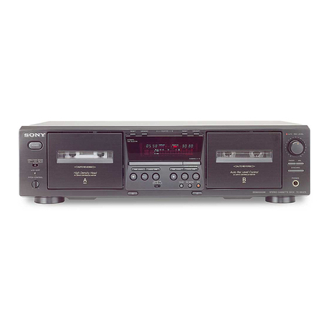
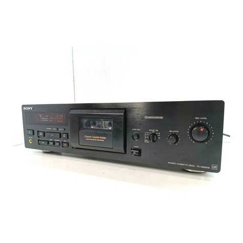
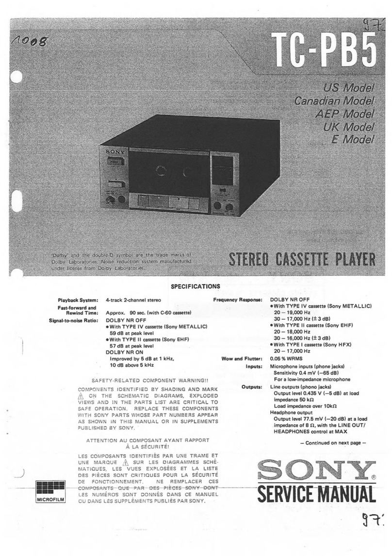
Sony TC-188SD User manual

Mode!
E
Model
SPECIFICATIONS
GENERAL
Frequency
Response:
DOLBY
NR
OFF
Power
Requirements:
110V,
120V,
220V,
240V
ac,
50/60
Hz
With
Ferri-Chrome
cassette
20—16,000
Hz
(NAB)
Power
Consumption:
11W
30—15,000
Hz
+3dB
(NAB)
Dimensions:
Approx.
440
(w)
x
145
(h)
x
290
(d)
mm
30—15,000
Hz
(DIN)
17
1/4
(w)
x
53/4
(h)
x
113/g
(d)
inches
With
chromium
dioxide
cassette
20—16,000
Hz
(NAB)
30—15,000
Hz
+3dB
(NAB)
|
30—15,000
Hz
(DIN)
TAPE
RECORDER
SECTION
With
regular
cassette
Track:
4-track
2-channel
stereo
20—14,000
Hz
(NAB)
Fast
Forward
30—13,000
Hz
(DIN)
Rewind
Time:
Approx.
90
seconds
with
Sony
cassette
C-60
Wow
and
Flutter:
0.08%
WRMS
(NAB)
+0.2%
(DIN)
S/N
Ratio:
DOLBY
NR
OFF
Weight:
Approx.
6.3
kg,
13
Ib
140z
*
‘Dolby’
and
the
double-D
symbol
are
the
trade
marks
of
With
Ferri-Chrome
cassette
Dolby
Laboratory
Inc.
Noise
reduction
system
manufac-
58
dB
at
peak
level
(NAB)
tured
under
license
from
Dolby
Laboratory
Inc.
56
dB
(DIN,
1975
rev.)
*0dB=0.775V
| |
48
dB
(DIN,
old)
With
chromium
dioxide
cassette
54
dB
at
peak
level
(NAB)
SAFETY-RELATED
COMPONENT
WARNING!!
DOLBY
NR
ON
Improved
by
5dB
at
1
kHz,
10dB
COMPONENTS
IDENTIFIED
BY
SHADING
ON
THE
sbove’s
Kuz
SCHEMATIC
DIAGRAMS
AND
IN
THE
PARTS
LIST
ARE
CRITICAL
TO
SAFE
CPERATION.
REPLACE
THESE
COMPONENTS
WITH
SONY
PARTS
WHOSE
PART
NUMBERS
APPEAR
AS
SHOWN
IN
THIS
MANUAL
OR
IN
SUPPLEMENTS
PUBLISHED
BY
SONY.
7
—
Continued
on
next
page
—
®
AANUAL
667
a
Sees
GR
kets
cont
nee
A
ase
2
seni

T=SGoU
Total
Harmonic
Distortion:
Bias
Frequency:
Inputs:
Outputs:
1.3%
105
kHz
MIC
(two
phone
jacks)
Sensitivity:
0.2
mV
(-72
dB)
Impedance:
for
low-impedance
microphone
LINE
IN
(two
phono
jacks)
Sensitivity:
0.06V
(-22
dB)
Impedance:
100
kQ
REC/PB
(connector)
Input
impedance:
less
than
10kQ
LINE
OUT
(two
phono
jacks)
Normal
level:
0.435V
(-5dB)
Load
impedance:
100
k2
suitable
load
impedance
more
than
10kQ
HEADPHONES
(binaural
jack)
Load
impedance:
for
low-impedance
headphones
REC/PB
(connector)
Output
impedance:
less
than
10k
0dB=0.775V

“L-L
MIC
REC/PB
$305
ANE
3
SI0l=
5
INPUT
SELECT
|
101-3
>
REC
MUTE
2)
r
>}
RV
101
i
el
5305-3
FORWARD
‘
REC
LEVEL
Se
'
LINE
AMP
BUFFER
AMP
>
;
Z|
D
FAST
F
Q105,
106
Q107
hm
L.
Rewind?
CNJ201-1
©
[LINE
OUT
INVYSVIG
WO01E8
5
\
3603
MUTING
“%
eta
PRESSING
DOLBY
NR
ONE
OF
FUNCTION
CIRCUIT
B+
\
BUTTONS
Q108~112
[HEADPHONE
101
RV103
METER
AMP
3|£
38
REC
LEVEL
a113
S10!-3
=
ae
S101-1
|
np
a
PLAYBACK
R-CH
aa
of
HRP
==
co
C4)
ME
101
sa
eet
D101
>
S
PLAYBACK
E
—
RECORD
.
—_
EQ
D301,
302
B+
Bren
R-CH
SERVO
AMP
CIRCUIT
HE
Saige
Q601~603
Q302
D303,
304
T301
e
R-CH
IS
OMITTED
/
308,
309

TC-188SD
|
2-1.
REMOVAL
SECTION
2
DISASSEMBLY
Top
Case
and
Bottom
Cover
Removal
Top
Case
Removal:
@-—@
Bottom
Plate
Removal:
@,
@
top
case
Oo
case
Screws,
@BW4x22
3)
case
screws,
®BW4x22
|
i
i
”
six
screws,
BV3x6
Vv
77
bottom
plate
Cassette
Lid
Removal
cassette
lid
|
A
cassetre
holder

TC-188SE
Deck
Mechanism
Removal
deck
mechanism
7)
Remove
the
record
link
plate.
@
Remove
cord.
PSW3x6
Cassette
Holder
Removal
Remove
four
retaining
rings
and
a
screw.
er
;
screw,
retaining
rings,
E
2.5
PTPWH
2.6x6
retaining
ring,
E
2.5
retaining
ring,
:
E2.5

TC-188SD
|
VU
Meter
Lamp
Removal
1)
Release
the
claws.
Panel
Removal
Pull
off
knobs.
©
é——
BV
3x6
(3)
@
Remove
tape.
—
:
lamp
Te
as
J
meter
escutcheon
(Part
No.
1-518-273-00)
a
[P<
meter
cover

|
TC-188SD
SECTION
3
ADJUSTMENTS
3-1.
MECHANICAL
ADJUSTMENTS
PRECAUTION
Clean
the
following
parts
with
a
denatured-
alcohol-moistened
swab:
record/playback
head
pinch
roller
erase
head
rubber
belts
capstan
idlers
Playback
Back
Tension
Torque
Adjustment
—
Playback
Mode
—
Use
type
CQ-102A
cassette
torque
meter.
Demagnetize
the
record/playback
head
with
a
head
demagnetizer.
(Do
not
bring
the
head
demagnetizer
close
to
the
erase
head.)
Do
not
use
a
magnetized
screwdriver
for
the
supply
reel
spindle
adjustments.
After
the
adjustments,
apply
a
suitable
locking
compound
to
the
parts
adjusted.
Ey
5.
The
adjustments
should
be
performed
with
the
rated
power
supply
voltage
unless
other-
wise
noted.
Change
the
hooking
position.
back
tension
fever
Tape
Path
Adjustment
—
Playback
Mode
—
1.
Make
an
adjustment
cassette
as
shown
below.
Specification:
2.5—3.5
g-cm
(0.035—0.048
oz-inch)
OE):
—
C-120
oS
Cut
out
hatched
tape
cassette
portions.
2.
In
playback
mode
and
viewing
from
the
front,
adjust
the
head
heights
to
eliminate
tape
curl
and
tape
twist
at
arrowed
portions.
erase
head
record/playback
3-513-237-01
(t=0.1)
3-513-237-11
(t=0.2)
Shim,
head
height
adjustment
screwdriver

Pinch
Roller
Pressure
Adjustment
—
Playback
Mode
—
Hook
the
pinch
roller
with
a
spring
scale.
Pull
the
spring
scale.
Slowly
return
the
pinch
roller
and
read
the
spring
scale
just
when
the
pinch
roller
starts
to
rotate.
pinch
roller
Shut-off
Time
Measurement
Specification:
Within
six
seconds
PAUSE
Timing
Adjustment
—
PAUSE
Mode
—
pinch
roller
ee
)
Bend
up
or
down.
Bend
here
and
adjust
the
position
of
pinch
roller
so
that
the
rotations
of
pinch
roller
and
reel
spindles
stop
at
the
same
time
when
slowly
de-
pressing
PAUSE
button.

Motor
Switch
(S602)
Position
Adjustment
Timing
Switch
(S601)
Position
Adjustment
—
Stop
Mode
—
—
Stop
Mode
—
Loosen
adjustment
screw
and
adjust
the
Loosen
the
screws
and
adjust
position
of
the
position
of
the
switch
for
the
specified
clearance
switch
bracket
as
marked
B
in
figure
below.
between
the
switch
leaves.
After
the
adjustment,
tighten
the
screws.
After
the
adjustment,
tighten
and
lock
the
screw
with
a
suitable
locking
compound.
motor
switch
(S602)
5.5—6.5mm
(7/32—VY%q")
timing
switch
(S601)
adjustment
screw
brake
release
lever
Contacts.
switch
bracket
Forward
Torque
Adjustment
—
Playback
Mode
—
Use
type
CQ-102A
cassette
torque
meter.
tension
arm
adjustment
plate
change
the
hooking
position
(Approx.
3g-cm/one
step)
Specification:
28—50
g-cm
(0.39—0.69
oz-inch)

TC-188SD
Fast
Forward
and
Rewind
Torque
Adjustment
—
Fast
Forward
and
Rewind
Modes
—
Use
type
CQ-201A
cassette
torque
meter.
Bend
the
spring
for
the
torque
of
55—95
g-cm
(0.77—1.3
oz-inch).
fly
wheel
"A
Bend
to
right
or
left.
spring
10
Muting
Switch
(S603)
Position
Adjustment
—
Stop
Mode
—
Loosen
the
adjustment
screw
and
adjust
the
position
of
the
switch
as
specified.
muting
switch
(S603)
7.0—1.5mm
to
contact
adjustment
screw
button
lock
plate

Vv
3-2.
ELECTRICAL
ADJUSTMENTS
Note:
The
adjustments
should
be
performed
in
the
order
given
in
this
service
manual.
The
adjustments
should
be
performed
for
both
L-CH
and
R-CH.
Switches
should
be
set
as
follows
unless
other-
wise
specified.
DOLBY
NR
switch:
OFF
EQ
switch:
NORMAL
BIAS
switch:
NORMAL
BIAS
and
EQ
switch
settings
in
accordance
with
tape
used
are
as
follows.
[tape
|
BlASswitch
|
EQswitch
Standard
Record
Supply
the
standard
input
level
signal
to
the
LINE
IN
jack
and
set
the
REC
LEVEL
control
to
obtain
the
standard
output
level.
Standard
Input
Level
:
0.77mV
|
0.25
V
input
level
(-60dB)
|
(-104B)
Standard
Output
Level
-HEAD-
load
impedance
|
100k2
50k2
0.44V
39mV
0.44V
output
level
REC/PB
100
k2
17mV
(-33
dB)
(-5
dB)
(-26
dB)
(-5
dB)
==
14
|
TC-188SD
Tape
Speed
Adjustment
Procedure:
Mode:
Playback
speed
checker
LFM-30
or
digital
frequency
counter
test
tape
WS-48
(3kHz,
0dB)
LINE
OUT
Adjust
RV602
to
obtain
the
specified
values
below.
Specification:
Frequency
difference
between
beginning
and
end
of
tape
should
be
within
0.7%
(20
Hz).
Adjustment
Location:
-
RV602
If
correct
tape
speed
cannot
be
obtained
by
adjusting
RV602,
Solder
CG)
or
(2).
servo
amp
board
601
®D
oT
Vi0
VIO
@-
Solder
portion
Tape
speed

TC-188SD
Record/playback
Head
Azimuth
Adjustment
Playback
Level
Adjustment
Procedure:
Procedure:
1.
Mode:
Playback
1.
Mode:
Playback
test
tape
P-4-A81S
VTVM
oo
cae
(6.3
kHz,
-10
dB)
(333
H
VTVM
100k2
|
7
z,
OB)
LINE
OUT
LINE
OUT
2.
Turn
the
adjustment
screw
for
the
maximum
0.55V
(-3
dB)
level
and
set
it
to
the
mechanical
mid
position
between
L-CH
and
R-CH
peak
position.
Adjust
RV102
(L-CH)
and
RV202
(R-CH)
to
obtain
0.55
V
(-3
dB)
VIVM
reading.
2.
Assure
that
the
LINE
OUT
level
does
not
change
when
the
mode
is
changed
from
play-
L-CH
back
to
stop
several
times.
peak
eb
sae
Specification:
LINE
OUT
level:
0.52—0.58V
R-CH
within
0.5
dB
(-2.5
—-3.5
dB)
adjustment
Peak
rr
Level
difference
between
channels:
Screw
shel
ae
Tce
less
than
0.5dB
3.
Mode:
Playback
Adjustment
Location:
test
oy
P-4-A81S
RV102
(L-CH)
RV202
(R-CH)
(6.3kHz,
-10dB)
L-CH
100k2
oscilloscope
te
&
O&
en
Ya
€
io
.
Sar
ae
ee
Oo
ms
ete
fe
3
Negecdiaameuats
ane
peer
whe
~
Lr
‘oe
ik
Bie
“3
a
ror
al
ea
we
“
LINE
OUT
Screen
pattern
in-phase
45°
90°
ade
180°
ed
good
wong
Adjustment
Location:
adjustment
screw

VU
Meter
Calibration
Procedure:
1.
Mode:
Standard
record
(See
page
11.)
af
osc
O
attenuator
14
O-—=-O
LINE
OUT
LINE
IN
0.44V
(-5
dB)
333.Hz,
0.25V
(-10dB)
2s
VU
meter
reading:
0
VU
Adjust
the
pattern
connection.
Specification:
When
the
LINE
IN
level
is
adjusted
to
make
0
VU
indication,
VTVM
reading
should
be
0.44V
(-5
dB).
Adjustment
Location:
‘
¢
€
+
ge”
8,
fn
ef
ez
rs
oe
ee
2
¢
4
a
ser
t+
&
CQ
ck
t,
aS
%
%
185
285
TC-1885D
Record
Bias
Adjustment
Procedure:
1.
Mode:
Standard
record
(See
page
11.)
af
osc
blank
tape
SONY
CS-10
10k
attenuator
O
St1,00
0
LINE
IN
5
ieee
7.7mV
(-40dB)
2.
Mode:
Playback
—
vrei
100
k22
[7]
im
LINE
OUT
Adjust
C153
(L-CH)
and
C253
(R-CH)
to
make
10kHz
and
1
kHz
signal
output
levels
equal.
Level
difference
between
the
two
output
levels:
OdB+1dB
Adjustment
Location:
C253
(R-CH)
C153
(L-CH)
4)
t
w
a's
of
atict,
7
.
an
gfe
-pher
as,
Pa
®
4a0
é
©
2
@
ry
at
ee
2
tose
t
a
a
pv:
3
ee
<5
7
Qe
on
SRE,
Ty
bas
a
a
€!
Pd
$
@.%o2
&
at
as
*
te
Pd
te
ne
Record
Level
Adjustment
Procedure:
1.
Mode:
Standard
record
(See
page
11.)
blank
tape
;
SONY
CS-1
af
osc
C$-20
CS-30
10k2
attenuator
O
ETE
|
O-——O
O
(1G
00
O
LINE
IN
333Hz,
0.25
V
(-10dB)
2.
Mode:
Playback
recorded
portion
VTVM
LINE
OUT
Adjust
RV103
(L-CH)
and
RV203
(R-CH)
to
obtain
0.44V
(-5
dB)
VTVM
reading.
3.
Change
the
blank
tape
to
CS-20
and
CS-30,
and
perform
the
same
record
and
playback
pro-
cedure.
Measure
LINE
OUT
level.
Specification:
SONY
tape
CS-10
CS-20
CS-30
Adjustment
Location:
0.41-0.46V
(-4.5
—-5.5
dB)
0.37—-0.52V
(-3.5
—-6.5
dB)
RV103
(L-CH)
RV203
(R-CH)
i
ee
ben
.
ose
ae
62
ae
ey
See
ny,
*
wae
©
ae
&.
&
re
eh
Sow,
en
She
a
eo
o-oo
re
or
Pe
ba.
ta
Py
earner
|
0
ory
=
‘
+4
~
pew
.<e
J
‘
nn
ie
A
ers
a
4
ae
as
®
*
ag?
Pima
¥
yaese
*
Ra
$¢%
&
a
yipit
terse
tener
a
OP
Bi
ep
"%
a
"
~~
oF
Qt
a
>}
7
hates
WER
ss
Si
Meh
34
pie
xe
Bip
eeee
Sie
ueaehS
|
esa
onal
.
a
.
”
a
i
eo
&
a
e.e"*
im
en
ea
Ke
:
aoe
Oe
Oe
2
ww
em
oo
*
me
*
tess
2
Ce
lad
uae
*
19
kHz
Filter
Adjustment
Procedure:
DOLBY
NR
switch:
ON
Mode:
Standard
record
(See
page
11.)
_
af
osc
LINE
OUT
LINE
IN
19
kHz
+20Hz,
0.25V
(-100B)
Adjust
the
pattern
connection
for
a
minimum
reading
on
VT
VM.
Adjustment
Location:
connect
132
133
;
232
(L-CH)
C539
(R-CH)
Me
C
«
:
,
aA
«
&
”
ua
“oe
“ee
'
oes

4-7.
MOUNTING
DIAGRAM
—
Conductor
Side
—
Repiacement
Semiconductors
For
replacement,
use
semiconductors
except
in
|
).
Q101-103,
105,
109).
0201-203.
205,
209
}
2SC632A
(2SC631A)
Q104,
106—108,
110—113
Q204,
206-208,
210-213
-:
2SC634A
(2SC633A)
0303,
601,
602
c
B
|
E
a
C B
QO302:
2801475
2SC1760
2801761
Cc
&
D101,201:
1T22A
(1T22)
D102,
104).
oes
Boe
ae
181555
(1$2076)
D103,
203:
17T22A
D301—304)
.
D308
309
f
10E2
(1GE1)
D307,601:
181555
(1T40)
cathode
“
anode
D305:
EGBO1-21
(EQA01-21R)
cathode
D306:
SLP24B
(LED)
cathode
anode
cathe.
»
anode
weap
Note:
@
®
@
@
۩
6
iy
parts
extracted
from
the
component
side.
parts
extracted
from
the
conductor
side.
#:
part
mounted
on
the
conductor
side.
Color
code
of
sleeving
over
the
end
of
the
jacket.
Readings
are
taken
under
no-signal
conditions
with
a
VOM
(20
kQ/V).
|
4
;
4
ae
4.
AC
voltage
readings
indicated
by
~*
in
the
bias
oscillator
:
Bt
pattern.
:
signal
path.
(GRY)
eo
record/FORWARD
FORWARD
circuit
are
taken
with
a
VTVM.
102
602
103
102
601
60l
iN
HO
,12
109
209
2l2
210
all
302
204
104
101
113
2131
101
201
nm
2
CNJ301
Kacy)
{VOLTAGE
SELECTOR
BOARD]
$306
VOLTAGE
BLUE
SELECTOR
sl
HE
EF135-36
Sa,
S603
T30l
POWER
M
DNF-10018
7
A
AYR
8,9
z
I
SK
7
WHT
|
BLK
WHT/GRY
a
cml
|
7?
Vid
3
RED
al
ene
RED]
|
WHT
CLAUDIO
AMP
BOARD]
MUTING
SWITCH
ON:
WHEN
PRESSING
ONE
\
OF
FUNCTION
BUTTONS.
/
WHT/RED
LO
Nem
“matonnatend
7
osname

[VOLTAGE
SELECTOR
BOARD]
ani
wi
POWER
iB
BLK
$406
VOLTAGE
[
SELECTOR
H)
VIO
S602
MOTOR
SWITCH
46v\
53V
|
WHT/GRY
en
|
GRY
|
$603
MUTING
SWITCH
Gaus:
PRESSING
ONE
OF
FUNCTION
BUTTONS.
/
WHT/BLK
A
i2
§
I4
WHT/RED
9
i
lor
1000"
ooon|
REC
LEVEL
0047
(5%)
Jt
Li]
(3
4
[M1C]
TAPE
BY
NR
2
il
[Bias]
—|
APE,
|—[
£0]
[DOLeY
NR]
10
oS
ae
ey
he
"
BRN]
<1
)
.
NORM
~
Fe-Cr
OFF
“i
is
aan
10,11
t
;
@
.)
J3
|
|
HIGH
Cr0e2
: :
E>
CLED
BOARDI
3601
TIMING
SWITCH
ME20I

\
TC-188SD
TC-188
|
a
4-2.
SCHEMATIC
DIAGRAM
(AUDIO
AMP
BOARD]
=
a
QIOl
2SC63IA
|
L-cH
1
se
(R-CH
IS
OMITTED)
|
MiG
Zeine
nee
MUTE
S601
TIMING
B.2V
ay
RIOS5
lOk18Va
R109
2.2k
REC/PB
S6OI-I
STOP
AA,
Ae
Sey
ee
CNJ201~1
:
%
eet:
re
7
{RE
Om
+
a
a
a
et
C102
10,
(5)
10/25V
|»
Jl
|
—o
«4
a
S$lol-5
oa
RVIOI
\
|
yt
We
:
$304
[OLB
AR]
e
82k(N)
$305-3
$304
-
|
SNS
Orr
4
QIO7
2SC633A
DAA
a
ge
eee
f
LINE
AMP
2sc633h
BUFFER
AMP
QIO8
2SC633A
—QIIO
2SC633A
III
2SC633A_—QII2._
2SC633A
02
EOL
Oatn
EQ
A
LINE
AMP
DOLBY
NR
CIRCUIT
DOLBY
NR
CIRCUIT
ado»
20.6V
euey
>
RiU3
33k
4.6V¥
Hay
Pree!
4
3
RiN2
270k
ISOK(N)
CH
Q!02
lO/I6V
RI46
LIO2
3.6k
33mH
R163
33k
R165
2.2k
C118,,0.0082
Se
RVIO3
0.6V
lees
aed)
lOk
DOLBY
NR
SWITCH
"ON
R127
330
RECORD
ia
fae
|
R123
120k
HRP
PFI45-3602A
|
Q301
2SCI760
D301,302
I0E2
VOLTAGE
RAGULATOR
RECT
bate
R178
SIO!
I8k
RECORD/PLAYBACK
NORM
—=Fe-Cr—=Cr02
oe
ON:
WHEN
PRESSING
ONE
~
2.2k
OF
FUNCTION
BUTTONS.
RI76
18k
D305
4.7K
EQAOI-
2iR
Q303
2SC633A
D307
IT40
QUIZ
2SC633A
pioi
|
IT22
|
104
‘2SC633A
D303,304,
308,
309
008
Grin
MUTING
HEADPHONE
METER
AMP
IOE1
=e
RECT
AOWETER
i)
()
[
J
|
oo
San
ee
ee
|
R-CH
1S
OMITTED
|
|
REFERENCE
NUMBERS
ARE
CODED
FROM
201
|
|
|
CASSETTE
(
C)
Hep
=~
|
|
|
|
—_—en
en
eee
Soe
ee
eee
eee
ele
eee
ee
eee
ee
re
ee
eee
ee
eee
eee
aa
ca
I
a
R305
R304
}
LOW
46V
LOW
l2V
:
NORM
NORM
13.7V
150 120
(Aceh
3y
)
G:
5
av
72w)
(172)
R306
eee
be
=
~
Y
Q302
C306
270
e
D306
SLP24B
ane
6°01
(1/2)
R303
°
REC
={_)
5
@*
3.3k
|
10306
EFI35
-36
R307
1C305
VV
VY
t
V
YY
i
v_Y
V
(i)
5
S60I-
2]
Si0I-6
y
1
C307.
33k
{5
$302-
0.018
35V
agen
&
|
|
5
3
$601
TIMINGero5
d
T
FORWARD
FAST
FORWARD
{LED
BOARD
}
REWIND
t
Q302
2SCI475
~+~«S302
‘(TAPE
SELECT
BIAS
BIAS
OSC
HIGH—=—
NORM—=—
LOW
ee
ge
eS
REL
ORD
rere
|
0.0047
Saniee
(5%)
INCLUDED
IN
—7—
$303
Ms
ener
pice
MaL
(
POWER
5
033k59%)
TAPE
SELECT
EQ
5603
!
bas
200
TRANSFORMER
:
.
MUTING
|
R183
[SERVO
AMP.
Q601,
602
2SC633/
BOARD
R604
4.3k
nen
TheO!
S-3k
r6e05
D6O0I
|
12k
]
ae
R6OI-|
lO/I6V
2.7k
[.2V]
(.2V)
Q601
)
A)
ne
REQE
TAPE
BS
Ik
SPEED
C60!
LMHICGO
100
~—*[100/
1OV
me
cee
meee
ee
sete
ce
ee
eee
ee
ek
ST
a
eee
————————————
-

IG
rT
FORWARD
IND
,
$304
|
$305-3
|
ae
ON==—
OFF
A
Rane
QI08
25C633A
Ql
2SC633A_
QIIl
2SC633A
~—s-
QII2.-:«
2SC633A
—
QIO9
2SC63IA
DOLBY
NR
CIRCUIT
DOLBY
NR
CIRCUIT
hens
(
SERVO
AMP
|
Q60I,602
2SC633A
Q603
2SCI76I
sa
{[-O---05
‘kK
BOARD
Sea
cad
SERVO
AMP
CIRCUIT
FILTER}
ie
|
|
Th6O!
ie
C129
560p
ee
leone
ican!
nl
bay
50k
Sp
(|
iL
i
oe
9
I
=R6O0I-|
0.0027
2.7k
(5%)
RI46
Lid?
LIO3
36k
33mH
92mH
2147
=o
39k
0.0033
R135)
RIS3
0.01;
47]
R154
6.2k
DlO2
1S2076
DI03
IT22A
DI04
1S2076
[-9
_
.
:
. : ,
.
-
ns
_—
0
| | |
|
sa,
|
.QBOl
2SCI760.
301,302
10E2
:
5
|
ie
3
a
|
VOLTAGE
RAGULATOR
RECT
|
[VU
METER]
|
CIS!
|
lO/I6V
10)
N
INCLUDED
IN
RMAL
|
POWER
c
TRANSFORMER
PRESSING
ONE
22k
7
NCTION.
BUTTONS,
D305
QU3
2Sc633A
DIOL!
IT22
10303.304
308,309
HEADPHONE
METER
AMP
|
ro
INCLUDED
1OE1
RECT
ee
en
eer
ee
ee
eee
ee
|
JIN
METER
CASSETTE
Note:
.
Components
for
right
channel
have
the
same
values
as
for
left
channel.
Reference
numbers
are
coded
from
201.
All
capacitors
are
in
uF
unless
otherwise
noted.
pF
=yuF
50WV
cr
less
are
not
indicated
except
for
electrolytics.
All
resistors
are
in
ohms,
4W
unless
otherwise
noted.
@
6
©
6
©
6
@
kQ
=
10002,
MQ
=
1000
k2
Adjustable
resistors
have
characteristic
curve
B,
unless
otherwise
noted.
(N):
low-noise
capacitor
and
resistor.
5%
indicates
component
tolerance.
:
Bt
bus.
|
[__]:
panel
designation.
|:
adjustment
for
repair.
“i
-
direct
connection
to
points
marked
—
on
the
chassis.
v7:
chassis
ground.
Voltages
are
dc
with
respect
to
ground
unless
otherwise
noted.
Readings
are
taken
under
no-signal
conditions
with
a
VOM
(20
kQ/V}.
(
record/FORWARD
i
I:
FORWARD
AC
voltage
readings
indicated
by
*
in
the
bias
oscillator
circuit
are
taken
with
a
VT
VM.
Voltage
variations
may
be
noted
due
to
normal
produc-
tion
tolerances.
Position
Switch
Ref.
No.
Switch
$101
RECORD/PLAY
BACK
(L-CH)
$201
RECORD/PLAY
BACK
.
(R-CH)
S301
|
POWER
$302
|
TAPE
SELECT
BIAS
S303.
|
TAPE
SELECT
EQ
S304
|
DOLBY
NR
$305
INPUT
SELECT
REC:
MUTE
S306
|
VOLTAGE
SELECTOR
S601
TIMING
S602.
|
MOTOR
S603
|
MUTING
Note:
The
components
identified
by
shading
are
critical
for
safety.
Replace
only
with
part
number
specified.
PLAYBACK
iPLAYBACK
OFF
LOW
NORM
OFF
MIC
FAST
FORWARD
|
REWIND
|
OFF
OFF
STOP
|

A
Bo
C
D
E
Note:
e
Items
with
no
part
number
and/or
no
gnarsorea'®
4.847-808-00
ck
+
ae
@
BW4x
22
‘ase,
top
description
are
not
stocked
because
they
:
.
are
seldom
required
for
routine
service.
e
All
screws
are
Phillips
(cross
recess)
type
unless
otherwise
noted.
ie
(—)
=
slotted
head
2
©
Circled
letters
((A)
to(@))
are
applicable
to
~
European
models
only.
X-3550-704-0
@
Side
Board
Ass’y
{L),
ornamental
X-3550-705-0
|
X-3544-004-2
©
Side
Board
20)
Lid
Ass’y
(A),
cassette
3-831-441-XX
®
ornamental
3-544-028-01
@
(0.3)
mae
Baacees
8
fh9
3-831-441-XX
®
OWE
eet
At)
Sheet,
(t0.5)
Spacer
BV
3x6
7
Wz
rr
x
—
4
“O
wn
|
be
4-847-802-00
ee
@
BW4x
22
®
©
rv
3-544-026-00
®)
TS
0
©)
x
Knob,
timer;
TIMER
ee
-
STAND
BY
<<
Ti
=
K
=
us
F
™~
‘
;
a
OO
Q
ex
si
X-3552-204-0
©
:
Panel
Ass’y
Q
Plate,
bottom
cb
Y
X-4842-602-2
®
Knob
Ass‘y,
lever;
INPUT
SELECT/
REC
MUTE,
DOLBY
NR,
EQ,
BIAS
X-4809-908-X
X-3552-202-0
©
la
cae:
Knob
Ass’y,
REC
LEVEL
3
2
12
©
BV
3x6
BV3x6
ac
‘Holder,
transformer
3-§52-211-00
©
O1
3-545-418-00
@
Panel,
rear
NO
Spring
7
A-2175-001:A©
lg
feel
Oe
See
the
Exploded
View
5-3.,
5-4.
on
page
24
and
25.
perthaidionk
Le
cain
BV3x6
i
ome
;
B3x6
1
3-513-211-00
®
3-552-214-00
Label,
dolby
Label,
specification
aA
Soe
og
a
oe
:
oS
er,
plastic
4.5mm
dia.
Rom»
aB
<
’
a
9-911-825-42
®
3-646-090-11
(@)
Cord,
dial
0.5mm
dia.
Rivet,
plastic
Plate,
side
(L)
aoe
“|
S
Ae
BV
3x6
Ne
7
~
ae
a
BV
3x6
a
aaa
Heat
Sink,
Je
|
QO
re
Ga
1-516-976-XX
507-501-
CG
-
Switch,
slide;
AgciPe
Spee
Minne
|
ene
;
o.
U-GA
_~
(8101,
2011
(CNJ101,
201,
J4)
ee
cei
'
|
Sees
Pee
als
a
Red
.
B|
EF
es
we
Holder
te
switch
|
|
BV
3x6
,
|
a?
Real
:
er
/
A
OG
(ac
Co.
Complete
Circuit
Board,
REC/PB
amp
2
3541-323-
X-4809-908-X
®
Ss
ae
pang
pei
Nr
:
MF
Foot
Ass‘y
—
>
|
:
avax6
AS
255070800
@
.507-476-XX
.
1-552-063-00
:
tee.
Oe
ues
(33)
a
Laan
lever;
DOLBY
NR
(S304)
Holder,
wire
1-520-295-00
®
P4xi2
Meter,
VU
(ME101,
201)
\
BV
3x6
1-552-039-00
©
Ao
:
Switch,
lever;
BIAS
(S302)
es
ofp
5
Frame,
record
lever
N
t
P..
SB.
“
1-552-038-00
©)
Ny
«
BV
3x68
:
oy
Switch,
lever;
EQ
(S303)
e
aw
:
Re
‘gl
|
ev
3x6
Nigh
ae
ey
;
F
1-00
Supplied
with
Jack
&
:
yy
rien
-00
©
20k2;
gS
REC
LEVEL
{RV101,
201)
Ry
BX”
PS3x5
Ae
;
eas
RY
Supplied
with
Veriable
Resistor
qT
aa
—
?
PSW3x6
‘gas
WN
?
SS
\
783x50
3
Sub-plate
Plate,
side
{R}
PS
3x
10
_-
a
—
me
a“
aa
a
"7507.65.00
Rivet,
plastic
Se
:
ee
ane
no
;
see
&
Lever,
record
limiter
Note:
3-552-212-
Escutcheon,
meter
1.552.080-00
©
e
it
ith
no
part
number
and/or
no
Switch,
slide;
INPUT
SELECT/
:
etre
WN
p
|
eer
Ries,
description
are
not
stocked
because
they
BV
3x6
Sub-chassis
Printed
Circuit
Board,
LED
are
seldom
required
for
routine
service.
ns
ns
oe
snes
8
e
All
screws
are
Phillips
(cross
recess)
type
unless
otherwise
noted.
(—)
=
slotted
head
e
Circled
letters
((A)
to(Z))
are
applicable
to
European
models
only.
Note:
The
components
identified
by
shading
are
critical
for
safety.
Replace
only
with
part
number
specified.

C
TC-18850
TC-18835D
ee
|
—
7
5-3.
|
PTP
2x5
PTPWH
2.6x6
5-2.
Shield
Plate
(top},
head
3-519-§22-00
®
Clamper,
lead
See
the
Exploded
View
5-5.
on
page
26.
3-543-903-00
@)
Hinge
PTPWH
2x8
3-513-211-00
@
Label,
dolby
3-646-090-11
@
Rivet,
plastic
PTPWH
2x6
B2x8
af
Lug,
2.6mm
dia.
(oa
1-507-501-00
(@®
~~
Plate,
pin
jack
(CNJ101,
201,
J4)
Frame,
record
lever
&
3
S
S)
=
Items
with
no
part
number
and/or
no
description
are
not
stocked
because
they
are
seldom
required
for
routine
service.
e
All
screws
are
Phillips
(cross
recess)
type
e
Circled
letters
((A)
to(Z))
are
applicable
to
OD
>
Sc
2
®
—
s
a
-
3
Cc
ge
8-825-584-00
®
8
She
Shes
=
fo)
re)
ee
Head,
eco
Pay
oe
$3
<
Co
a
eooreneno
©
a
PF
145-3602A
(HRP)
~o
g
o
Oo
oD
Head,
erase;
EF
135-36
(HE}
a
~
ee
3
n
oO
,
3-513-237-01
®
(0.1)
N3
:
se
OD
.
ds
3-513-237-11
@
(0.2)
e
8
=
s
fe)
=
;
Spacer,
head
height
adjustment
a
1
e
.
ogre
!
:
S
.
S
Oo
0
f
ring
.
:
9
ter
o
3-542-476-00
®
BA
}
Shield
Plate
(bottom),
head
«
%
Spring
X-3462-050-0
®
f
a
s
@
i
©
Pulley
Ass’y,
fast
forward
E2
8
be
a
Ld,
3-542-439-00
®)
>»
~Y
8
@
ad
ey
3
we
Plate,
head
deck
&
X.3562-4
13.0,
©
:
in
ever
Ass’y
%
.
3
@
=e
LJ
E15
J
ee
3-542-438-00
®
.
8
&
8
o)
:
Deck,
head
?
S
2
;
db
s
*
S
gs
ze
3-542-475.00
®
@
'y
\9
g
aR
@°
3s
‘9
&
Spring
G3
-
mp
<
<3
8
2
3-701-441-11
®
(20.25)
eo
:
Q83
§
\
\
Sc
led
®
(t0.5)
ds
vt
bs
iS
88
§
er,
plastic
4mm
dia,
ROB
ny
;
&
X-3542-416-0
®
8
ot
hae
oe
&
a
}
=
Lever
Ass’y,
back
tension
;
ges
S
,
=
ten
:
3-533-222-00
®
€,
Oss
Ow
2
>
os
Shaft,
head
%
y
‘
8
“
©
3-542-466-00
®
x8z
/
©
ices:
“Ae
Spring,
pinch
roller
@
|
38
;
re
CT
-—
2
3-491-256-XX
®
2
=
2
gz
:
F3
©
=
Roller,
head
deck
™
/
~~
om:
ars
s
ose
/
Y¥
6
Brake
Lever
Ass‘y,
including
b~
2.
ole
=H2
/
©
e*
‘x=
n
part
marked
@A
A
3
/
os
:
QO
8
=
/
”
3
-§48-09
1-
ae
\
ze
=
8>
a
5
Lever
Ass‘y,
forward
Uecaecived
seta}
©
\
gs
he
,
/
\
oS
co
2
/
moe
:
X-3543-902-0
D
(8x
nm
e&
Gack
ehs
Sees
Plate
Ass’y,
shut-off:
including
~
\ns8
7
P=
s
parts
marked
*
A—R
8
\
&
com
(®
E-R
on
page
25)
@
ae
2
>
&
\
a
cS
2
‘
bh
~
i:
i
=
f=
3-535-425-00
®
%
=
>
n
Cap,
supply
reel
e8
an
ee
>
Q.
Spring
(187)
Holder,
counter
3
2
ae
\
pS
2
3-542-468-00
§
88
Rs
\
Ssu
<=
X-3536-421-0
©
Spring,
earth
®
Ro]
gs
a”
©
2s
2°
>
a
ow
red
—
Beas
,
Supporter,
chassis
2
:
y
a
a=
2S
—
'
*B
8
a
a
Pie
\
wo
2
2s
:
3-538.053.00
®
™
Bs
[
\
sw
9
Fu
un
Cap,
take-up
reef
:
=6
lo
S
mG
pad
q
PTPWH
2.6x6
:
3
°
“hed
34
-~
>
3-543-911-00
®
3
[poke
cbs
x
8
~
=
Spring
7A
2
™,
See
&
c
X-3536-404-5
©
pay
tee
‘;
3
0
3-701-437-11
B®
BOE
SOO
AY
END
PSW3x6
-
[a
s
wz
pacligld
plastic
(t0.25)
3
a
mm
dia.
3-541-170-00
©
3-534-276-00
af
"
8
bd
8
Belt,
counter
6
Fy
Holder,
lamp
®
c
A
@
as
5
_
9
—
‘cum
3
Plate
Ass’y,
eject
lever
8
2
_
3
i:
c
2
ha
tone
AS
~
Sd
Ce)
pindle
Ass’y,
includin
;,
ie
=
os
eg
=
3
“
(om
pera
maked
RAD
9
Lever,
answering
record
2
Ss
re
c
pm,
x
a
e
3-500-128-00
ob
mats
:
3
:
8s
g
@
3
=
PI
$
3-531-869-00
&
Spring
°
<
/
Md
ge
8
3
>.
s
ro)
‘
ate,
record
preventing
SS
Sorin
9
N
>
3S
——
33
as
es
3
=
ras
Plate
Ass‘y,
pause
8
S,
Re
.
8
©
s
3
*%
$
vA
ae
mH
aA
>
3
:
ae
:
yf
z=
ad
38
S
1D
&
‘
ee
Su
i]
x
3
@®
.
Fu
x
:
oO
@
.
:
~
es
3
x=
3
La
3-543-907-01
®
3
S
Y,
©
Su
hy
Button,
REWIND.
——_-
£
§
=
GS
4
a
2
3-701-439-21
@
re
i
‘
>
mm
di.
J
3
,
en
3s
o/,
3
pate.
%
g
Washer,
plastic
3
dia.
(t0.5)
ess
g
x
a>
fe/
/[.~
3
4
Be
“ae
I2y
N38
Qs
2
a
Link
(A)
Ass’y
=
3
Ne
.
os
nae
Ys
\
=
WW
j
og
~~
.
y
Na
S
Y
3-543-908-00
®
;
Vas
ase
Y
Button,
STOP
Link
(B)
Asty
Q
<
©
y
Y
x
3-543-907-01
®
:
,
f
fa-<<
RY
3-543-910.00
®
Button,
FAST
FORWARD/
L
:
-
At
rs
Button,
EJECT
SY
FORWARD
|
y
ee
;
ify
F2
sth
ry
wee
~
3-543-909-0090
®
=
iw
aii
aunom
Pause
3-637-079-00
®
Washer
{A}
E2
—
E2
—~~
3543-96292
@
——
Spring
.
3-531-869.XX
B)
t
3-542-463-00
®
Spring
(8),
push
button
|
a
:
Q
=
|
|
|
SS
i
s
8
p
d
w>
Soring
(547)
<
=
he
tes
|
4-812-499-XX
®
(Ou
Lock
Plate
md
;
:
os
~
|
Spring
(157)
E2
—&
re
3-543-969-00
@®
<i
a
>
:
Lever
(A],
pause
.
:
s
-
@8
Spring
(C}
(
;
3-543-963-00
®
$
3
7
2
ao’
©
8
.
e,
Spring,
lock
plate;
pause
:
*
es
8
—
5
§
rar
8
o>
O§
3
Ag
“|
os
2
2
SN
=
Lock
Plate
(8),
pause
ui
S48
XA
Q
9
8
3-543-905-00
®
;
Pe
XO
4
©
oly
Spring,
buttons
e
g
Za
es
A
is
Fes
2
ee:
x
2g
*
.
7)
xX
Sx
re)
8
Lever
(C),
pause
23
<
s
°
§
‘
rSabsiagi
re
®
Note:
3
ete
or”
pring
(8),
push
button
a.
Varia
athe
He.
Hark
inutiben
GAIEe
kO
3
x
Seieass
oot
description
are
not
stocked
because
they
3
Spring
(A],
push
button
are
seldom
required
for
routine
service.
5
3-460-077-00
®
©
All
screws
are
Phillips
(cross
recess)
type
Lug,
wire
binder
untess
otherwise
noted.
(—)
=
slotted
head
@
Circled
letters
((A)
to(Z)
are
applicabs
€
to
European
models
only.
@
(QOT)
shows
the
number
of
coils
in
spring.

TC-188Si
5-4.
‘|
X-3543-902-0
@D
Plate
Ass‘y,
shut-off:
including
parts
marked
*
A—R
‘*
Ae
x.35420
©
(*
A—D
on
page
24)
Idler
Ass’y,
fast
forward
y,
7
ane
eee
ee
we
ee
ee
ee
ee
ee
Belt,
shut-off
3-542-458-00
®
|
3-464-103-XX
®
7
Spring
(20T}
X-3543-906-0
©
3-701-439-01
®
Tension
Arm
Ass’‘y
Washer,
plastic
3mm
dia.
(t0.13)
@F2
Flywheel
Holder
Ass‘y,
including
Part
marked
@A
3-536-455-00
@
Spring,
tension
arm
3-542-451-00
®
Spring,
fast
forward
*O
*P
PTPWH
2.6x6
paige
ged
®
=
Lever
(B),
fast
forw.
a
PTP
26x6
|
|
3-464-103-XX
@®
PTP26x6
PTPWH
2.6x6
|
Spring
(20T)
L
a
|
~
~
~
Plate,
release
brake
3-543-978-00
®
3-489-073-00
@
!
Belt
Screw,
thrust
3-491-163-00
®
Rubber,
brake
ke
Pes
;
3-531-865-00
®
|
3-543-955-00
®
aan.
Spring
—
ever,
muting
|
Ps
eL
]
I
|
|
|
|
|
|
L
|
X-3543-920-0
©)
e
)
4-812-499-XX
®
2?
Flywheel
Ass’y
|
Spring
(167)
ESDP
Cushion
(t5)
PTPWH
2.6x6
3-542-472.00
®
Plate,
eject
stop
»
Spring
3-513-128-00
©
Oil
Seal
timing
Lever,
record
i
SS
PTPWH
2.6x6
3-472-222-XX
@
3-543-904-00
@
es
Spring
(41T)
Spring,
thrust
a
=
~
3-464-103-XX
®
é
3-701-443-4171
@
:
PTPWH
2.
6
3-70
1-437-11
®
°
5
5
)
6x
Washer,
plastic
2mm
dia.
Spring
(20T)
S
Washer,
plastic
5mm
dia
(t0.25)
(00.25)
'9:911-815-02
©
Cushion
(t5)
Plate,
release
lock
3-701-437-21
®
Washer,
plastic
2mm
dia.
(t0.5)
3-701-443-21
@
Washer,
plastic
5mm
dia.
(t0.5)
Lever
(Aj,
record
3-542-473-00
®
Spring
Note:
PTPWH
2.6x6
>
Lever
(A),
rewind
@
Items
with
no
part
number
and/or
no
:
3-542-481-00
®
description
are
not
stocked
because
thy
3
Spring
are
seldom
required
for
routine
service.
@
All
screws
are
Phillips
(cross
recess)
type
unless
otherwise
noted
3-701-443-2171
:
4
(—)
=
slotted
head
Washer,
plastic
5mm
dia.
(0.5)
©
Circled
letters
((@)
to
@)
are
applicable
to
X-3543-916-1
@®
European
models
only.
ever
(B)
A:
@
(COT)
shows
the
number
of
coils
in
spriny.
Link
Plate,
record
Lever
(8B)
Ass’y,
record
=
«
ey:
PTPWH
2.6x6
8-835-006-00
Motor,
ONF-10018
(M)
/
1-516-853-XX
©
Switch,
leaf;
motor
(S602)
Shield
Band,
motor
3-542-450-00
®
PTPWH
2.6x6
Lever
(A),
fast
forward
Holder,
timing
switch
1-516-815-00
©
Switch,
slide;
timing
(601)
3-489-112-00
@
Cushion,
rubber
3-543-975-00
®
Pulley,
motor
3-542-464-00
@
Py
Spring,
lock
plate;
button
|
|
P1.4x3
7
PTPWH
26x6
Printed
Circuit
Board,
servo
amp
1-516-853-XX
©
Switch,
leaf;
muting
(S603)
1-224-630-00
®
Resistor,
variable
4702
{R602}
3-643-979-11
@
Screw,
motor
5
3-542-461-00
®
Lock
Plate,
button
Table of contents
Other Sony Cassette Player manuals

Sony
Sony TC-K561S User manual

Sony
Sony WM-FX197 Marketing User manual

Sony
Sony TC-K333ESG User manual

Sony
Sony Walkman WM-FS233 User manual

Sony
Sony WM-EX10 User manual

Sony
Sony TC-WE435 User manual

Sony
Sony SLV-E850B User manual

Sony
Sony Walkman WM-FX241 User manual
Sony
Sony TC-K611S User manual

Sony
Sony WM-FS555 - S2 SPORTS WALKMAN User manual

Sony
Sony Walkman WM-EX422 User manual

Sony
Sony M-530V User manual

Sony
Sony CFS-W318 User manual

Sony
Sony Walkman WM-GX100 User manual

Sony
Sony Sports Walkman WM-ES392 User manual

Sony
Sony CFS-1075S User manual

Sony
Sony WM-EX5 User manual

Sony
Sony TC-WA8ES User manual

Sony
Sony CFS-929SMK2 User manual

Sony
Sony Walkman WM-FX488 Setup guide