|
TC-W32/W290
|
TABLE
OF
CONTENTS
;
MODEL
IDENTIFICATION
DecHOn
atte
Fuge
-
Specification
Label
-
TC-W32
Specifications
PROC
P
HORE
O
EME
HORDE
OEE
E
EEO
OH
HEE
HEED
O
EOE
EHEH
OOOH
ESO
EERO
OS
1
TC-W290
1.
SERVICING
NOTE
ictieseissesscecssisactscsteeissecancsnese
cones
ks
SONY.
move.nnoWww
2.
GENERAL
Identifying
the
Parts
Wig
0:
ws0io0;e
0.00;
00!
0.998
whe
00.6,
056-050-060:
.0-0
pete
cee:
6°
6oez8c6:0:6.
Sree
ce
o%0K6
4
|
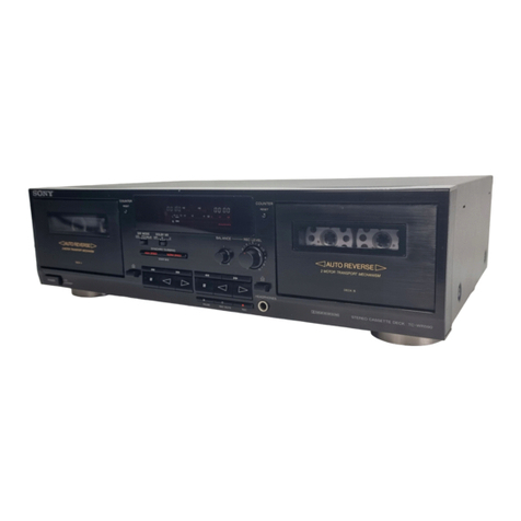
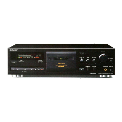
STEREO
CASSETTE
DECK
y
MLL
3.
ADJUSTMENTS
CCZ=ZH7@|H/
$@MM0"@@#t6"##
3-1,
Mechanical
Adjustments
Eee
eerer
eee
ee
eee
ee
ee
ee
ee
ee
5
3-2.
Electrical
Adjustments
POCO
eee
m
eee
e
eee
Hera
eee
neers
eHeeneeeeseres
5
4.
rabid
:
SERIAL
NO.
me
‘
OC.
lagram
PTH
HEHEHE
STD
HOHHEHHHEHHHH
HHH
SHH
HHO
HEHEHE
RHO
RHEE
4-2.
Printed
Wiring
Boards
OC
OOOO
TOO
OCT
T
Il
MADE
IN
JAPAN
4-3,
Schematic
Diagrams
©
010.6615:
0;
6.6.0":
08
ei
e
606%
0.026.660.
6:6U
Oere
(ee
te.
Celeieoe.
8
15
US,
Canadian
Model
:
AC
120V
60Hz
15W
5.
EXPLANATION
OF
IC
TERMINALS
----+-------
esses
seer
ee
19
AEP
Model
:
AC
220
—
230V
~
50/60Hz
:
E
Model
:
AC
120, 220,
240V
6.
EXPLODED
VIEWS
~
50/60Hz
15W
6-1.
Chassis
Section
PER
EREE
TERT
EG
OTT
IOTR
AE
ROOT
OT
22
Australian
Model
:
AC
240V~
50/60Hz
6-2.
Front
Panel
Section
COCO
EEHe
errr
He
HOH
H
ROLE
EH
EO
HORE
EES
ESO
E
OD
23
6-3.
Mechanism
Section-1
(TCM-21OW1)-rrrrstseereeeeeeeees
24
6-4,
Mechanism
Section-2
(TCM-21OW
1
):srrrrreseeeeee
rene
25
Operating
voltage
(E
model)
7.
ELECTRICAL
PARTS
LIST
vr
-s-rereeresrresesseseess
26
Operate
the
unit
on
either
120,220
or
240V
AC,
50/60Hz,
Before
connecting
the
unit
to
the
power
source,
check
that
the
operating
voltage
of
your
unit
is
the
same
as
the
local
power
line
voltage.
The
voltage
selector
is
located
on
the
rear
panel.If
the
selector
must
be
reset,
disconnect
the
AC
power
cord
and
set
the
selector
to
the
appropriate
voltage.
VOLTAGE
Selector
VOLTAGE
.
ATTENTION
AU
COMPOSANT
AYANT
SAFETY-RELATED
COMPONENT
WARNING!!
RAPPORT
A
LA
SECURITE!
COMPONENTS
IDENTIFIED
BY
MARK
A\
OR
DOTTED
LINE
LES
COMPOSANTS
IDENTIFIES
PAR
UNE
MARQUE
/\
WITH
MARK
f\
ON
THE
SCHEMATIC
DIAGRAMS
AND
IN
THE
PARTS
LIST
ARE
CRITICAL
TO
SAFE
OPERATION.
REPLACE
THESE
COMPONENTS
WITH
SONY
PARTS
WHOSE
PART
NUMBERS
APPEAR
AS
SHOWN
IN
THIS
MANUAL
OR
IN
SUPPLEMENTS
PUBLISHED
BY
SONY.
SUR
LES
DIAGRAMMES
SCHEMATIQUES
ET
LA
LISTE
DES
PIECES
SONT
CRITIQUES
POUR
LA
SECURITE
DE
FONCTIONNEMENT.
NE
REMPLACER
CES
COMPOSANTS
QUE
PAR
DES
PIECES
SONY
DONT
LES
NUMEROS
SONT
DONNES
DANS
CE
MANUEL
OU
DANS
LES
SUPPLEMENTS:
PUBLIES
PAR
SONY.

