Sony WALKMAN WM-9 User manual

Refer
to
MDR-W3
Service
Manual
issued
previously
SERVICE
MANUAL
for
information
of
headphones
supplied
with
this
set.
AEP
Model
UK
Model
E
Mode!
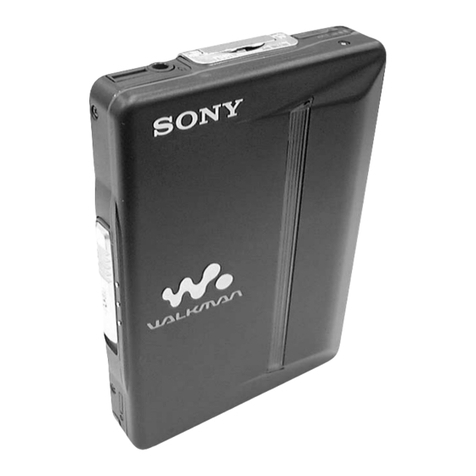
Photo:
Silver
type
EE
a
a
a
Se
SPECIFICATIONS
Tape
Track:
4-track
2-channel
stereo
Dimensions:
Approx.
91
x
142x
36.5
mm
(w/h/d)
Fast
Winding
Time:
Approx.
2
min.
30
sec.
with
Sony
cassette
C-60
(35/s
x
55/s
x
1%16
inches)
Frequency
Response:
40
—
15,000
Hz
not
incl.
projecting
parts
and
controls
(with.
the
TAPE
selector
set
to
METAL)
Weight:
=
Approx.
370g
(13.1
02)
incl.
batteries,
not
incl.
40
—
15,000
Hz
other
accessories
(with
the
TAPE
selector
set
to
NORM)
Power
Output:
35mW-x
2
(max.)
25
mW
x
2
(at
10%
harmonic
distortion)
at
de
Operation
Power
Requirements:
6
Vv
dc,
four
IEC
designation
R6
batteries
(size
AA)
OdB
=
0.775
V
Battery
Life
(continuous
playback
[
;
[
hours):
Approx.
5
hours
with
supplied
Sony
SUM-3
Tape
Transport
Mechanism
Typs
Mee
(NS)
New
Super
batteries
Approx.
10
hours
with
Sony
Eveready
AM3
alkaline
batteries
:
For
maximum
performance
we
recommend
the
use
of
alkaline
batteries.
STEREO
CASSETTE
PLAYER
SONY.
TC
MICROFILM

WM-9
SECTION
1
DISASSEMBLY
Note:
Follow
the
disassembly
procedure
in
the
numerical
order
given.
CABINET
(B)
AND
BATTERY
CASE
LID
REMOVAL
®ey
@
PTT2.6x6
cabinet
(B)
OPTT2.6x6
battery
case
lid
CABINET
(A)
REMOVAL
@
rrrT26x6G
S&
©
Vn
cabinet
(A)
SN
Ds
:
XX
SS
QS
-

SECTION
2
oy
ADJUSTMENTS
2-1.
MECHANICAL
ADJUSTMENTS
[
PRECAUTION
1.
Clean
the
following
parts
with
a
denatured-
alcohol-moistened
swab:
playback
head
pinch
roller
capstan
idlers
rubber
belts
2.
Demagnetize
the
playback
head
with
a
head
demagnetizer.
(Do
not
bring
the
head
demag-
netizer
close
to
the
erase
head.)
3.
Do
not
use
a
magnetized
screwdriver
for
the
adjustments.
4.
After
the
adjustments,
apply
suitable
locking
compound
to
the
parts
adjusted.
5.
The
adjustments
should
be
performed
with
the
rated
power
supply
voltage
unless
otherwise
noted.
Head
Height
Adjustment
1.
Prepare
an
adjustment
cassette
as
shown
below.
C-120
Cut
out
hatched
tape
cassette
portions.
2.
In
playback
mode
and
viewing
from
the
front,
adjust
the
head
heights
to
eliminate
tape
curl
and
tape
twist
at
portions
shown
by
arrow.
playback
head
3-578-138-01
(t=0.1)
3-578-138-11
(t=0.2)
Shim,
head
height
adjustment
Torque
Measurement
Meter
Reading
25-45
g-cm
(0.34—0.62
oz.inch)
more
than
70
g-cm
(0.97
oz
inch)
1-4
g-cm
Forward
CQ-102B
Fast
Forward
and
Rewind
Tape
Tension
Measurement
Meter
Reading
CQ-403A
more
than
130
g
(4.59
oz)
CQ-201B
CQ-102B
Pinch
Roller
Pressure
Measurement
—
Playback
Mode
—
C2]
Slowly
return
the
pinch
roller
and
read
the
spring
scale
just
when
\
the
pinch
roller
starts
rotating.
(The
capstan
should
first
contacts
here.)
pinch
roller
Qtension
gauge
250-330
g
(8.82—11.64
oz)
Flywheel
Thrust
Play
Adjustment
—
Playback
Mode
—
dc
ammeter
terminals
of
the
battery
case
1.
Turn
the
thrust
screw
counterclockwise
until
the
screw
tip
leaves
from
the
flywheel
shaft.
2.
Gradually
turn
the
thrust
screw
clockwise.to
the
position
where
the
motor
current
suddenly
increases.
3.
Then,
turn
the
thrust
screw
counterclockwise
about
%
turn
from
the
position
obtained
in
step
2.

WM-9
WM-9
MEMO
:
2-2.
ELECTRICAL
ADJUSTMENTS
Serrrrrrrrrery
Issa
adroit
acetate
epi
a
sca
elt
cp
oa
Go
a
et
eek
DIY
catty
os
|
|
Tape
Speed
Adjustment
Lpiaiaee
Head
Azimuth
Adjustment
PENI
I
IUET
EPPA
SE
SERE
AP
OSEMTASERERS
SE
Dt
pe
UPON
ENe
Tanes
Mnenerereeccaayscennseessiseserivehecgereseessteduecesssesssteussiseevscctccsarenauinracdanevesvevarssesdacessrssecceususssdenenusensesenssesseecossecscoevoesddsceseareuvedeccdenven
Setting:
Procedure:
seeecivaedoaednaniasbbabeceessnsestensnnesdesebabontennaddan
donc
uosuansaneisinicai
loos
aanabiowtelast
doe
nsvdcbsocsgpdbedblebdloga
dues
cesotsbscigenwinidechincll.
casi
te.
ccncteossaes
VOL
control:
mechanical
mid
1.
Mode:
playback
test
tape
P-4-A063
srstesseevasnnssesassenanscaseesscsssssceeesenstanseusccansestuastoasansssccasecssuesussacsusssnusssusesssessssesssessusssuasesavessusssauessvsssssessussssacssussssssssussesnssssusssassssissssasssisesussessbeataveseeecseeccesecesceese.
Procedure:
(6.3
kHz,
-10dB)
Mode:
playback
seoanesosdcsiesgsbagsito
seca
ea
bese
ised
covovye
sasshns sesctca
vate
couscnsacola
Vaphsbcbclscssespocoousbasevataacrecicicuusw
sce:
sloed
Resa
etbhacbatsabgeaecuaneleacck
disposes
eres
ee
en
ee
oe
a
ree
eee
erst
ee
ot
ene
ee
ete
PRR
test
tape
eee:
WS-48
322
2.
Turn
the
adjustment
screw
for
the
maximum
Aas
nrate
a
rented
rete
eek
ela
pel
ee
al
ee
Rt
cea
eh
a
output
levels.
If
these
levels
do
not
match,
turn
the
adjustment
screw
until
both
of
output
seseeeecescasaensceneenananaasenesenanannssssnassensssssonssetessennsunneasessnsnsusssessssssssssncsesssssannnanssssseesssunsesceessssnvesesssssseseesessesgnuandenecessssanassssesssssssdesesssstutsssscssssiseeececssssesseseeccces
levels
match
together
within
1.5
dB.
SEAN
ABEREPERSE
SSIS
ODS
BEN
PERCHA
ELAS
CA
TPRSRORTORenMreLenseAN
odsneEsesesaedveeaservencosee
see
serdestesashensnsssnssnubecésvnveusveaseneesperesebeneensenes
see
aedbosiosestedbudecdierevencdevescstcasssabedsedvseseescoheveovedeesssécessnece
HEADPHONES
ssrevesenensesennsosssnnessesasesesavenessassscnsccnsncassnesssnsueneaussssessssnonssasanenssssnensassosusatunessusassesessssecssssesscusessssssesssesuesessssssscsuassesassuarsasasassucacassssueacsesesivevasersasaroseeseuescuseeceesce
L-CH
within
’
peak
1.508
,
—
within
PEE
seg
a
Bk
i
aa
i
lasek
ae
at
tne
Specification:
ae
y
1.58
i
Digital
frequency
counter
2,950
—
2,970
Hz
Marnevesseseneasavenssnssasensoseueiaseasuessencncsussassesasssvenssssasssavsnenaaasasoucscsssssussnnsaesseanscssensotsuesesssenssesssusuensassssessesusessssesuseceususasseassassuscsssasaesusasassucarassesssecscsususaverensesseseeseece
R-CH
'
F
diff
between
beginning
and
Screw
Pek
!
requency
difference
oe
een
beg
g
position
—»
angle
stesersseacaracersneseneasareacessssanensorsrercansssssennconanensensassessasscesensnsasnsnouasssasananenanensasesssoseseratatossosssaneasessarsceceesssassacgenesasesseesseosessaneesnagssnsseasaesnenesestassessssssescenseasesesersesecee:
end
of
tape
should
be
within
+2%
(60Hz).
L-CH
R-CH
peak
peak
sasssnsennsenenecesssessssecuscevcecusasanssasseuscsunsccssessasccsvesssssotsnsesnusssusesssscssssessssssnuesseseuanessntossnesusssssusesessssesssessuussssesssusssusessuvegnusesnuecsusestisessusssusssisessauessevesasessavsesaveusecesses
Adjustment
Location:
3.
Phase
Check
Mode:
playback
sesvevasessccunecsssoucnsecnetanenseensensecavorsscanessusbasccussnsessscessssusssscssscsuussncsesssasosasesssassesussssssasssuscansesssssssssesssausanussavecuscsarssussuuesascssscsuerasesssssusessussusseresuscusesudesaecesecescesecs
test
tape
P-4-A063
RV601
(6.3
kHz,
-10dB)
L-CH
322
oscilloscope
inphase
45°
90°
135°
=:
180°
C
—~-
—J
Wy
good
wrong
Adjustment
Location:
adjustment
screw
oO
|
WM
Playback
Level
Adjustment
—
Muting
Level
Adjustment
Setting:
Setting:
Power
supply
voltage:
-4.0
V
de
VOL
control:
maximum
Procedure:
Procedure:
Mode:
playback
Mode:
playback
test
tape
P-4-L320
(315
Hz,
~10dB)
vie
E
HEADPHONES
P-4-L300
(315
Hz,
OdB)
VTvM
HEADPHONES
Confirm
that
the
signal
is
output
at
HEAD-
Specification:
PHONES.
Level
difference
between
channels:
. ; :
less
than
3
dB
If
necessary,
connect
the
pattern
®
and
firm
the
above
procedure.
1.
If
necessary,
connect
a
resistor
(R103
or
R203)
on
the
conductor
side
for
lower
level
channel.
2.
Confirm
that
the
output
level
of
HEAD-
PHONES
is
fixed
when
repeating
playback
and

SECTION
3
DIAGRAMS
3-1.
MOUNTING DIAGRAM
SIZE
"AA"
T
{IEC
DESIGNATION
R6
ye
4PCS
6V
BLK
[SERve
AMP
BOARD
RED
|
moor
(&
ORG
BLK
ey
|
8
-2.5V
Servo
amp
board
is
supplied
with
M1.
HP301
s
PLAYBACK
PP227-
3602D
INPUT
(GRY)
R-CH
RED
WS
a
(GRY)
PLAYBACK
~
[INPUT
L-CH
ae
a
eee
a
nae
$302
{POWER)
R~CH
QUTPUT
J30I
L-CHOUTPUT
$301
METAL
/Cr02
NORM
-7
D30I
BATTERY
Note:
@
Color
code
of
sleeving
over
the
end
of
the
jacket.
@
o—:
parts
extracted
from
the
component
side.
@
¢—:
parts
extracted
from
the
conductor
side.
e
Mm
:
part
mounted
on
the
conductor
side.
5
at
©
am
pe:
signal
path
@
mma
meee
©
L-CH
signal
path
©
smmee
seme
>
R-CH
signal
path

A
B
Cc
D
E F
G
H
|
a
A
-
Ss
2
‘o)
3-2.
SCHEMATIC
DIAGRAM
[MAIN
BOARD]
ay
+
£303
at
G02
IC
301
CX887
;
Ta
lov
PREAMP/POWER
AMP
:
R307
®
Semiconductor
Lead
Layouts
7
3.3V
|
-2.4V
“ov
-33V
le
oi07
+
RuIO
2SB1013
CX-887
C9) (8)
()
oe)
50V
GND
VEE
NC
1¢
301
(172)
aH
Rail
3.9
(1/4W)
i
1
J30!
,
or
=
R
E
Cc
B
L-CH
-L7V
HP30I-|
x
pp227-3602p
“>
>
|
Z
RIPPLE
a
iM
PHONES
FILTER
3.9(1/4W)
PREAMP
;
C3
2)
@
~1.7V
R104
[0k
SLP-161B
short
long
cathode
anode
RIO6
220k
~1.9V
R108
33k
(1/4W)
+
R107
3.9k
(1/4W)
Po
w
<
“Sra
O
mow
of
S
te
PLAYBACK
LEVEL(L)
4
v¥V
$301-I
TAPE
MUTING}
R305
NORM—=
METAL
|
130
|
/Cr02
©
B8tvawi
TO
THE
MEASURING
POINT
ON
THE
BOARD
ov
|
©
7
DRY
BATTERY
.
:
1
oi
Size
“aa”
rete:
F
in
uF
herwi
es,
FE
2
<L
(IEC
DESIGNATION
R6)
©
All
capacitors
are
in
uF
unless
otherwise
noted.
pF:
Miu
3
4PCS
6V
5O0WV
or
less
are
not
indicated
except
for
electrolytics
c2o7t
Relo
thy
ties
and
tantalums.
REW
ona
©
All
resistors
are
in
ohms,
1/¢W
unless
otherwise
noted.
kQ
:
1000
2,
MQ
:
1000
k2
R—-CH
REFERENCE
J
©
(C7):
panel
designation.
ses
tt)
ld
al
e
C_):
adjustment
for
repair
HP30I-2
oy
PREAMP
Ba
;
;
pp227-seo20
CPA
pee
-3.3V
e
——-—:
B-
bus.
Q301
S—y
$302
®
Voltages
are
de
with
respect
to
ground
unless
otherwise
POWER)
noted,
~17V)
a4
.
Lv
.
I
we
av
ce
OD)
a
|
T
=.
@
Readings
are
taken
under
no-signal
conditions
with
a
ago!
R204
10k
“i.
R206
220k
=1.9V
}
-L.7V
_
—_
VOM
(50
k@2/V).
0
iati
i
{605
ceostt
cid
-
C205
R209,
Q301
2SBI013
blag
R.
R
e
Voltage
variations
may
be
noted
due
to
normal
produc
oa
(aw)
Kaw)
302
‘RIPPLE
FILTER
a
tion
tolerances.
|
¢201
R202
°
c204
«R207
€305
270
RV
©
Total
current
is
measured
with
no
cassette
installed.
270
3.9k
7
;
0.6012
regs
0.015
59k,
Woe
cog
ft
lov
|
|
©
Switch
5008
é
lie
|
b
@
SPEED
()
Ae
Position
t,
pias
(/74w)
R303.
*
030!
(@)
GB)
L7V
4
430
(4)
BATTERY
R
PLAYBACK
LEVEL(R)
Led
.
$301-2
¢
©
s=s=
:
signal
path
‘f
NORM
Ss
METAL
D301
SLPI6I
ov
i
-6V
I
2
.
Note:
Voltages
are
measured
with
a
VOM
(50kQ2/V),
|
ISERVO
AMP
BOARD]
|
es
|
Servo
amp
board
is
supplied
with
Mi.
=~9~
|
—10—

SECTION
4
EXPLODED
VIEWS
AND
PARTS
LIST
__WM-9
_WM.9
|

WM-9

WM-9
GENERAL SECTION
ACCESSORY
_&
PACKING
MATERIAL
No.
Part
No.
Description
No.
Part
No.
Description
1
3+305-653-00
PLATE
(A),
BLIND
101
3-316-112-00
CUSHION
2
3-309-406-00
TERMINAL
BOARD
(8),
BATTERY
102
3-316-117-01
INDIVIDUAL
CARTON
3
3-309-407-00
TERMINAL
BOARD
(C),
BATTERY
103
=
3-316-115-00
SPACER
4
3-309-408-00
TERMINAL
BOARD
(D),
BATTERY
104
=
3-570-631-71
BAG,
POLYETHYLENE
5
3-309-417-41
(SLIVER)...LID,
BATTERY
CASE
105
3-703-707-01
STICKER,
SONY
SYMBOL
(21)
5
3-309-417-51
(RED)......LID,
BATTERY
CASE
106
3-572-854-00
BELT,
SHOULDER
5
3-309-417-61
(BLUE).....LID,
BATTERY
CASE
107
3-578-101-00
(RED,BLUE)....PLATE,
ORNAMENTAL
6
3-309-442-00
TERMINAL
BOARD,
BATTERY
(A)
108
3-701-311-00
(RED)......LABEL,
PRODUCT
COLOR
7
3-309-443-00
SPRING,
LEAF
109
3-701-314-00
(BULE).....LABEL,
PRODUCT
COLOR
8
3-310-718-00
SPRING
110
3-703-729-00
(SILVER)...LABEL
(SMALL),
COLOR
9
3-316-108-11
(SILVER)...CABINET
(A)
111
=
3-773-617-11
(AEP)......MANUAL,
INSTRUCTION
9
3-316-108-21
(RED)......CABINET
(A)
112
3-773+617-41
(UK).....
«
MANUAL,
INSTRUCTION
9
3-316-108-31
(BLUE).....CABINET
(A)
113.
3-773-617-51
(AEP,E)....MANUAL,
INSTRUCTION
10
3-316-110-21
PANEL,
CONTROL
114
3-793-828-11
QUESTIONNAIRE
11
3-527-213-00
LABEL,
SERIAL
NUMBER
115
8-951-151-91
MDR-W3
SET
12
3-892-318-00
SCREW,
SMALL
13°
3-831-441-XX
CUSHION
14
3-849-356-00
SPRING,
COIL
15.
7~621-255-15
SCREW.
+P
2X3
16
=
7-685+134-14
SCREW
+P
2.6X8
TYPE2
NON-SLIT
17
=
7-685-780-04
SCREW
+PTT
2X3
(S)
18
7-685-781-01
SCREW
+PTT
2X4
(S)
19
7-685-792-04
SCREW
+PTT
2.6X6
(S)
20
9-911-815-02
CUSHION,
BATTERY
LID
21
=9~911-816-01
RIBBON,
BATTERY
22
A-3239-154-A
BUTTON
ASSY,
STOP
23
X-3316-103-1
(SLIVER)...CABINET
(B)
ASSY
23
X-3316-103-2
(RED)......CABINET
(B)
ASSY
23
X-3316-103-3
(BLUE).....CABINET
(B)
ASSY
24
=
X-3316-104-1
(SILVER)...LID
ASSY,
CASSETTE
24
X-3316-105-1
(RED)......LID
ASSY,
CASSETTE
24
=©X-3316-106-1
(BLUE).....LID
ASSY,
CASSETTE
25
9-911-839-XX
RUBBER
(B)
26
3-310-707-00
SHAFT,
CASSETTE
LID
27
=:
3-316~423-00
KNOB,
VOLUME
NOTE:
CAPACITORS:
*
The
mechanical
parts
with
no
reference
MF:
uF,
PF:uuF.
number
in
the
exploded
views
are
not
supplied.
RESISTORS
:
*
All
resistors
are
in
ohms.
*
Items
marked
"
6"
are
not
stocked
since
FE:
fl
1
they
are
seldom
required
for
routine
>
nonflammable
service.
Some
delay
should
be
antici-
COILS
pated
when
ordering
these
items.
k :
*
MMH
:
mH,
UH
:
pH
*
Due
to
standardization,
parts
with
part
numbers
(A-AAA-AAA-XX
or
4-ASAA-AAA-X)
SEMICONDUCTORS
may
be
different
from
those
used
in
the
In
each
case,
U:
u,
for
example:
set.
UA-++:
A+++,
UPA---:
UPA---,
UPC---:
UPC,
*
If
there
are
two
or
more
same
circuitsin
a
UPD---:
uPD---
set
such
as
a
stereophonic
machine,
only
typical
circuit
parts
may
be
indicated
and
capacitors
and
resistors
in
other
same
circuits
may
be
omitted.
ps
1
4-—-

MECHANISM
SECTION
No.
Part
No.
Description
BELT
(42.5X1)
RETAINER,
FLYWHEEL
301
3-306-803-00
302
@;3-306-806-00
303
ceeeeeseeees
304
3-306-816-00
305
3-306-823-00
306
3-306-826-00
BELT
(30.5X0.9)
LEVER,
SHUT-OFF
SHAFT,
LOCK
PLATE
307
3-306-827-00
308
;3-306-828-00
309
=
3-306-829-00
COLLAR,
HEAD
COLLAR,
MOTOR
CUSHION,
MOTOR
310
3-306~-830-00
311
3-306-842-00
SCREW,
FITTING,
HEAD
LEVER,
EJECT
312
3-306-853-00
LEVER,
FWD
313
3-306-855-00
LEVER,
REW
314
3-306-856-00
LEVER,
FF
315
3-306-858-00
SPRING
316
3-306-859-00
SPRING
317
3-306-861-00
SPRING,
TENSION
318
3-306-862-00
SPRING
319
3-306-863-00
SPRING
320
3-306~864-00
SPRING
321
3-306-866-00
SPRING,
TENSION
322
3-306-867-00
SPRING
323
3-306-872-00
SPRING,
COMPRESSION
324
3-306-876-00
SPRING
325
3-306-878-00
326
—3-306-879-00
327
3-306-880-00
LEVER,
DETECTION
GUIDE,
TAPE
PLATE,
LOCK
328
3-306-896-00
329
@;3-306-882-00
330
3-306-883-00
SLIDER,
SE
CHASSIS,
HEAD
LEVER,
RELEASE
331
3-316-104-00
332
3-316-105-00
333.
3-316-106-00
BUTTON,
PLAY
BUTTON,
FF
BUTTON,
REW
334
3-508-108-XX
335
3-531-794-00
336
3-545-715-00
SPRING,
TENSION
SPRING,
TENSION
WASHER
337
3-547-625-00
338
=
3-564-949-00
SCREW,
THRUST
ADJUST
SPRING,
TENSION
339
3-701-437-11
WASHER
340
3-578-138-01
SEAM
341
=
3-578-138-11
SEAM
342
3-578-223-11
WASHER
343
3-590-523-00
344
cee
eeescves
345
3-701-467-00
WASHER,
STOPPER
SCREW,
LOCK
NOTE:
*
The
mechanical
parts
with
no
reference
number
in
the
exploded
views
are
not
supplied.
*
Items
marked
"
6"
are
not
stocked
since
they
are
seldom
required
for
routine
service.
Some
delay
should
be
antici-
pated
when
ordering
these
items.
*
Due
to
standardization,
parts
with
part
numbers
(A-AA\-AO4-XX
or
A-AAAA-AAA-X)
may
be
different
from
those
used
in
the
set.
+
If
there
are
two
or
more
same
circuitsin
a
set
such
as
a
stereophonic
machine,
only
typical
circuit
parts
may
be
indicated
and
capacitors
and
resistors
in
other
same
circuits
may
be
omitted.
Now
346
347
348
349
350
351
352
353
354
355
356
357
358
359
63
360
361
362
6;
CAPACITORS:
MF:
uF,
PFruuF.
RESISTORS
*
All
resistors
are
in
ohms.
F
:
nonflammable
COILS
*
MMH
:
mH,
UH
:
uH
SEMICONDUCTORS
In
each
case,
U:
UA---:
upA---,
UPA---:
pPA-->
UPD---:
uPD---
45
—
MECHANISM
SECTION
Part
No.
7-627-552-57
7-627-553-37
7-624-101-01
7-624-1
02-04
7-624-1
05-04
7-624-1
06-04
7-621-995-35
7-685-780-04
X=3306-804-0
X-3306-807-0
X-3306-813-0
X-3306-815-0
X-3306-816-0
X-3306-817-0
X-3306-820-0
X-3306-830-0
X-3309-601-0
Us
for
example:
»
UPC---:
pPC,
Description
SCREW,
PRECISION
+P
1.7X5
SCREW,
TOTSU
P=
2x3
RING,
RETAINING
E-1.2
STOP
RING
1.5,
TYPE
-E
STOP
RING
2.3,
TYPE
-E
STOP
RING
3.0,
TYPE
-E
SCREW,
PWH
2X5
SCREW,
TOTSU
PTT
2x3
FLYWHEEL
(B)
ASSY
IDLER
ASSY,
FWD
PINCH
ROLLER
ASSY
LEVER
ASSY,
REW
IDLER
LEVER
ASSY,
FF
IDLER
SHAFT
ASSY,
T
IDLER
BEARING
ASSY,
REEL
FLYWHEEL
(A)
ASSY
CHASSIS
ASSY
WM-9

ELECTRICAL
PARTS
ELECTRICAL
PARTS
Ref.No.
Part
No.
Description
RefNo.
Part
No.
501
;1-611-265-00
PC
BOARD,
AUDIO
(MAIN)
R205
1-247-835-00
502
#;A-3260-200-A
MOUNTED
PCB,
MAIN
R206
1-247-887-00
.
R207
1-246-487-00
C101
=1-102-118-00
CERAMIC
0.001
2MF
10%
50V
C102
1-102-106-00
CERAMIC
LOOPF
10%
50V
R208
1-246-485-00
C103.
-1-123-616-00
ELECT
4.
MF
20%
25V
R209
=
1-246-473-00
R210
1-247-831-00
C104
=
=1-161-033-00
CERAMIC
0.
015MF
20%
25V
C105
=:
1+123+356-00
ELECT
LOMF
20%
16V
R211
1-246-415-00
C106
=
=1-102-123-00
CERAMIC
0.0022MF
10%
50¥
R301
1-247-817-00
R302
1-247-817-00
C107)
=:
1-123+351-00
ELECT
0.4
7MF
20%
50V
C201
=
1-102-118-00
CERAMIC
0.
00L2MF
10%
50V
R303
1-247-822-00
C202
=
1-102-106-00
CERAMIC
100PF
10%
50V
R304
1-246-457-00
R305
1-247-810-00
C203
=1-123-328-00
ELECT
4.
7MF
20%
25v
C204
=
1-161-033-00
CERAMIC
0.01
5MF
20%
25v
R306
1-246-477-00
C205
=1-123-617-00
ELECT
1
0MF
20%
16V
R307
1-247-871-00
C206
=
1-102-121-00
CERAMIC
0.0022MF
10%
50V
RV301
1-230-165-00
C207
=
1
-123-351-00-
ELECT
0.47MF
20%
50V
C301
1-123-307-00
ELECT
1
OOMF
20%
10V
$301
1-554-123-00
$302
1-554-024-00
C302
=
1-123-306-00
ELECT
47MF
20%
10V
C303
=
1-123-317-00
ELECT
22MF
20%
16Y
C304
=1~123-296-00
ELECT
220MF
20%
6.3V
C305
-
1-123-306-00
ELECT
47MF
20%
Lov
D301
8-719-901-96
DIODE
SLP161B
HP301
8-829-373-60
HEAD,
PLAYBACK,
STEREO
IC301
8-759-908-82
IC
CX-887
J301
1-507-915-00
JACK
(PHONES)
ML
8-835-075-11
MOTOR,
DC
(DNE-56008)
Q301
8-729-801-83
TRANSISTOR
2SB1013
R101
=.1-247-863-00
CARBON
22K
45%
1/6W
R102
1-247-817-00
CARBON
270
=
=5%
1/6W
R103:
1-247-815-00
CARBON
220
5%
1/6W
R104
=
1-247-855-00
CARBON
10K
5%
1/6W
R105
1-247-835-00
CARBON
1.5K
5%
1/6W
R106
=1-247-887-00
CARBON
220K
5%
1/6W
R107
=1-246~487-00
CARBON
3.9K
5%
1/4W
R108
1-246-485-00
CARBON
3.3K
5%
1/4W
R109
=:
1-246-473-00
CARBON
1K
5%
1/4W
Ril0
=
1-247-831-00
CARBON
1K
5%
1/6W
Rill
=
1-246-415-00
CARBON
3.9
5%
1/4W
R201
1-247-863-00
CARBON
22K
45%
1/6W
R202
1-247-817-00
CARBON
270
=
5%
1/6W
R203.
1-247-815-00
CARBON
220
5%
1/6W
R204
1-247-855-00
CARBON
10K
45%
1/6W
NOTE:
CAPACITORS:
*
The
mechanical
parts
with
no
reference
MFiuF,
PFepuF.
number
in
the
exploded
views
are
not
supplied.
RESISTORS
-
All
resi
in
ohms.
*
Items
marked
"
6"
are
not
stocked
since
Fb:
-
ie
ee
they
are
seldom
required
for
routine
se
NOME
Lerma
DLE
service.
Some
delay
should
be
antici-
COILS
pated
when
ordering
these
items.
:
*
MMH
:
mH,
UH
:
uH
-
Due
to
standardization,
parts
with
part
numbers
(A-AAA-AAA-XX
or
A-AAAA-AAA4-X)
SEMICONDUCTORS
may
be
different
from
those
used
in
the
In
each
case,
U
:
u,
for
example:
set.
UA--+-:
pA--+,
UPA---:
uPA---,
UPC---:
uPC,
-
If
there
are
two
or
more
same
circuitsin
a
UPD--+:
uPD---
set
such
as
a
stereophonic
machine,
only
typical
circuit
parts
may
be
indicated
and
_
Capacitors
and
resistors
in
other
same
circuits
may
be
omitted.
9-951-326-11
Sony
Corporation
—TE—
Description
CARBON
1.5K
5%
1/6W
CARBON
220K
5%
1/6W
CARBON
3.9K
5%
1/4W
CARBON
3.3K
5%
1/4W
CARBON
1K
5%
1/4W
CARBON
1K
5%
1/6W
CARBON
3.9
5%
1/4W
CARBON
270
«5%
1/6W
CARBON
270
=
5%
1/6W
CARBON
430
5%
1/6W
CARBON
220
5%
1/4W
CARBON
130
5%
1/6W
CARBON
1.5K
5%
1/4W
CARBON
47K
5%
1/6W
RES, VAR,
CARBON
10K/10K
(VOL)
SWITCH,
SLIDE
SWITCH,
LEAF
(POWER)
English
83K0692-1
Printed
in
Japan
©
1983
Table of contents
Other Sony Cassette Player manuals

Sony
Sony Walkman WM-FX463 User manual

Sony
Sony Walkman WM-FX161 User manual

Sony
Sony Walkman WM-EX9 User manual

Sony
Sony CFS-219 User manual

Sony
Sony S2 Sports Walkman WM-FS233 User manual

Sony
Sony Walkman WM-FX251 User manual

Sony
Sony Pressman TCM-21DV User manual

Sony
Sony TC-K679ES User manual

Sony
Sony Walkman WM-SP1 User manual

Sony
Sony Walkman WM-GX221 User manual

Sony
Sony TC-RE340 User manual

Sony
Sony TC-RX300 User manual

Sony
Sony WN-FX653 User manual

Sony
Sony CFM-D1JMK2 User manual

Sony
Sony SLV-EZ715AS User manual

Sony
Sony WALKMAN WM-FX453 User manual

Sony
Sony WM-FX822 User manual

Sony
Sony Walkman WM-EX678 User manual

Sony
Sony TC-WA8ESA User manual

Sony
Sony CFS-KW75S User manual