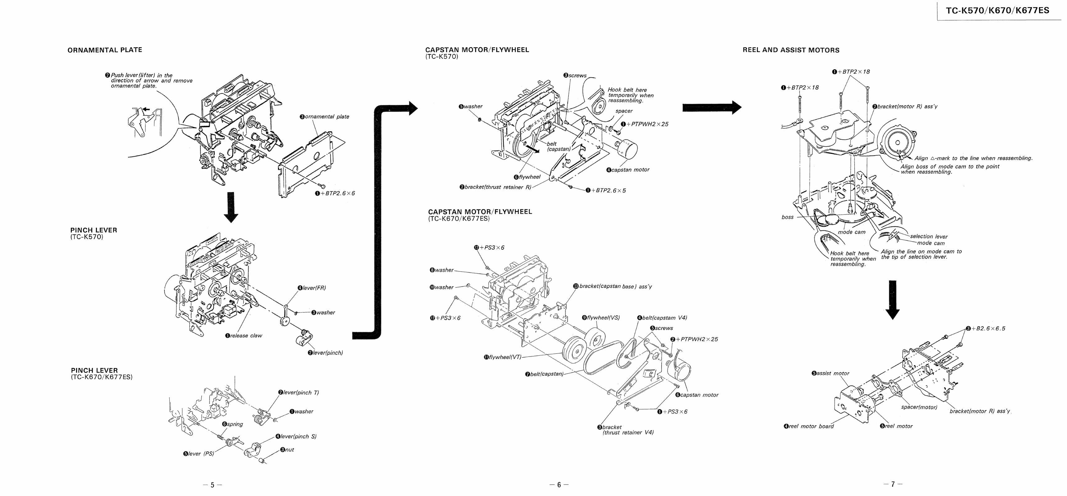
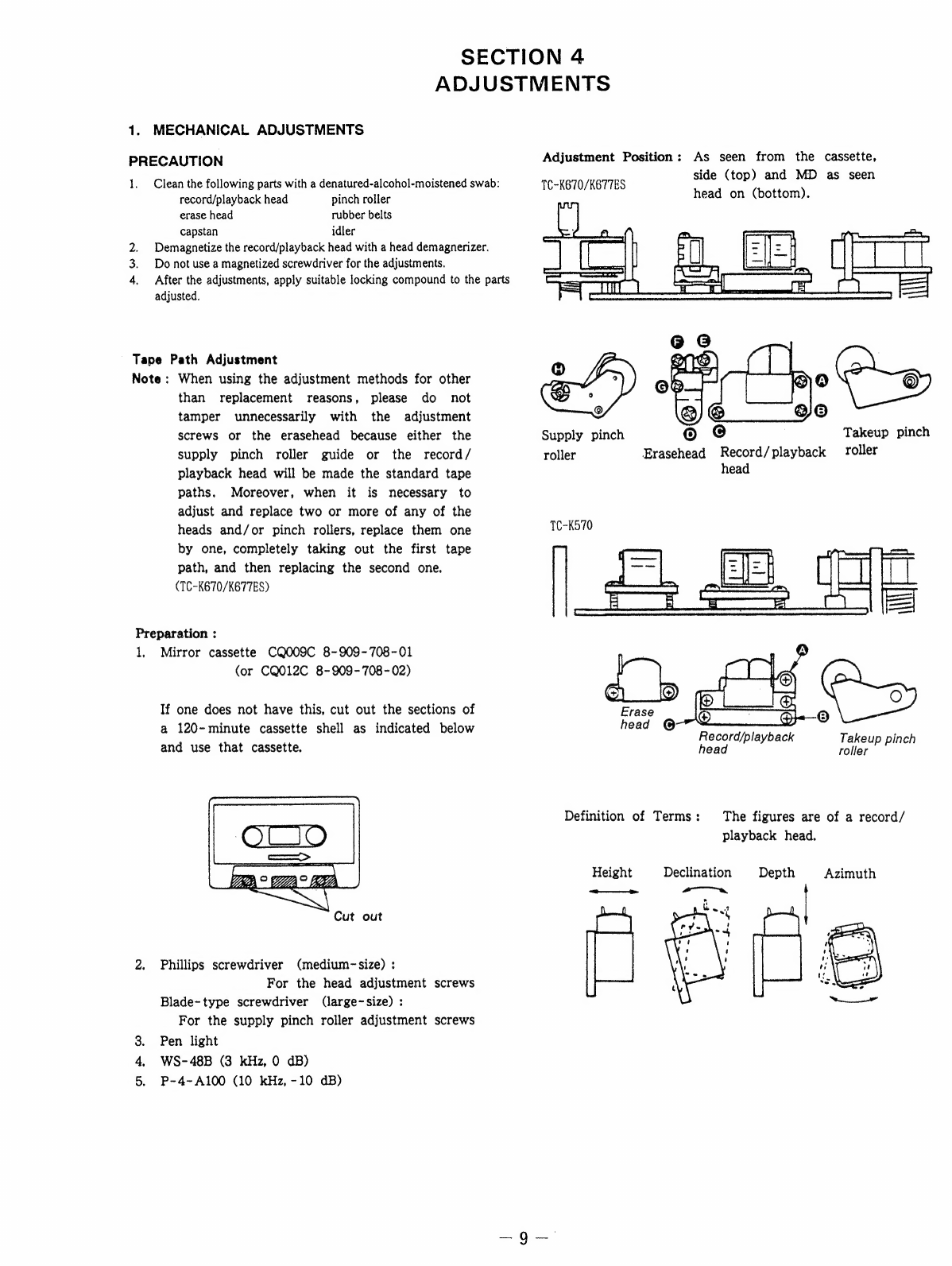
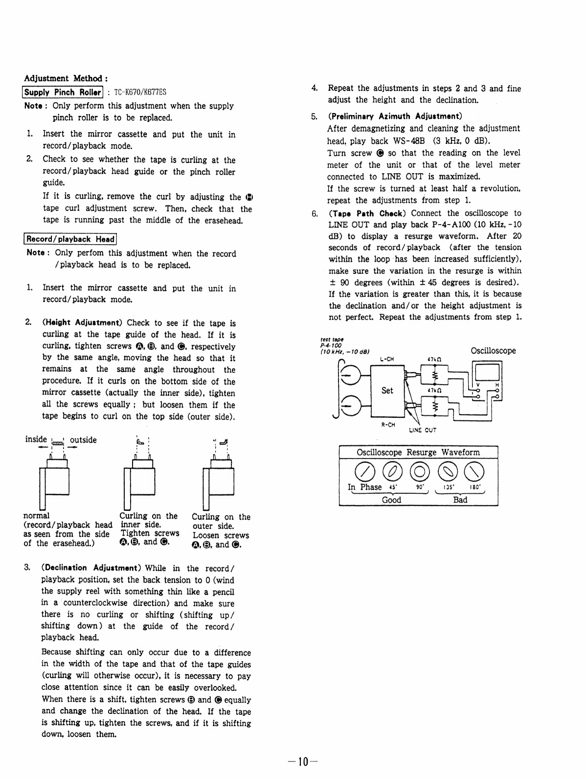
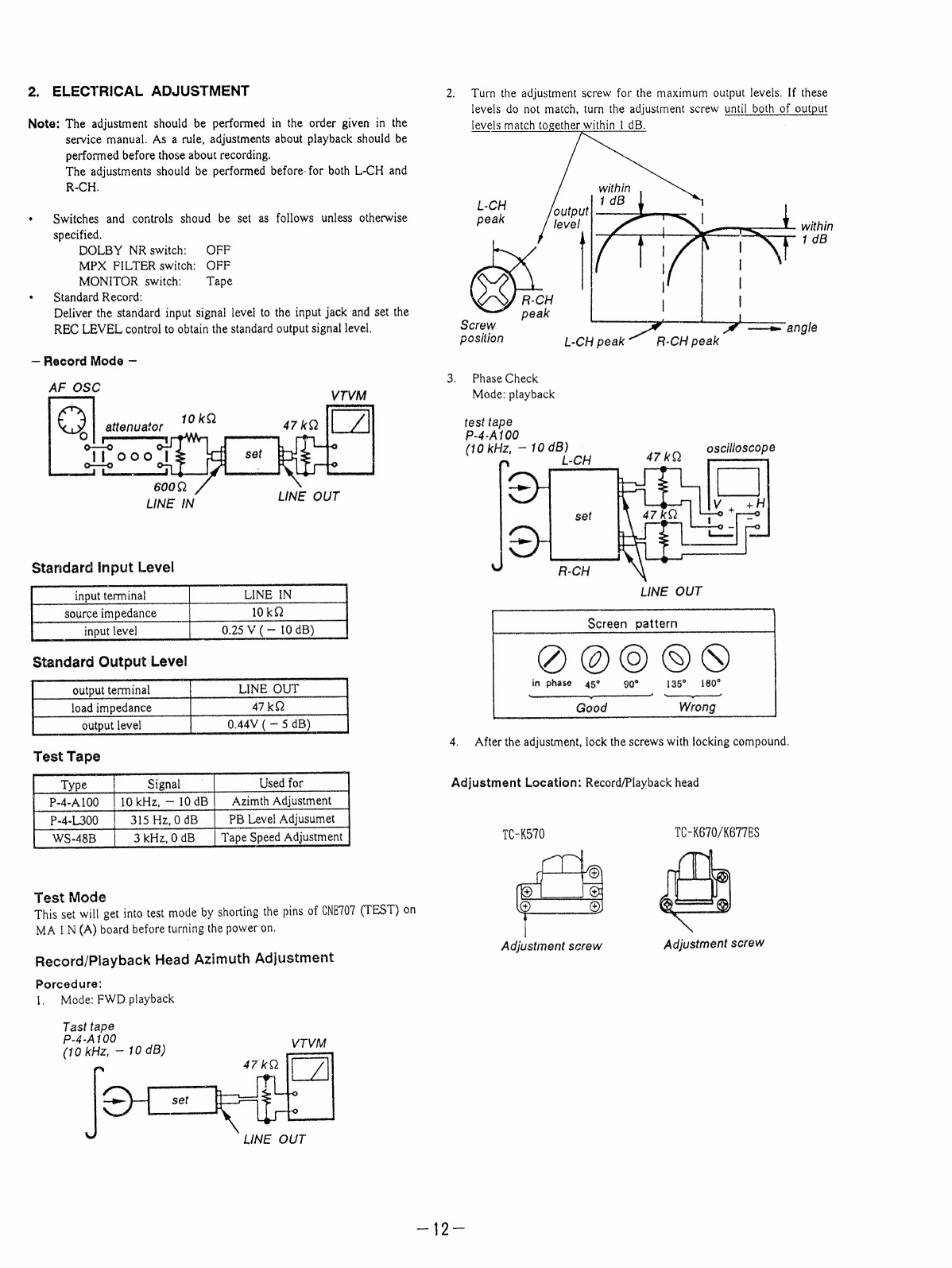
Sony TC-K570 User manual
Other Sony Cassette Player manuals

Sony
Sony TC-K615S User manual

Sony
Sony TCW-E475 User manual

Sony
Sony TC-WR550Z - Stereo Cassette Deck User manual

Sony
Sony WM-DDIII User manual

Sony
Sony WM-EX570 User manual

Sony
Sony Pressman TCM-929 User manual

Sony
Sony Walkman WM-FX700 User manual

Sony
Sony Walkman WM-EX900 User manual

Sony
Sony Walkman WM-EX660 User manual

Sony
Sony Walkman WM-FX571 User manual

Sony
Sony -Matic TC-110A Setup guide

Sony
Sony WalkMan WM-EX102 User manual

Sony
Sony Pressman TCM-4TR User manual

Sony
Sony TC-RE340 User manual

Sony
Sony WM-10 User manual

Sony
Sony TC-U30 User manual

Sony
Sony CFM-2300 Marketing User manual

Sony
Sony CFD-S36 - Cd Radio Cassette-corder User manual

Sony
Sony TC-WE405 User manual

Sony
Sony Walkman WM-FX551 Instruction Manual