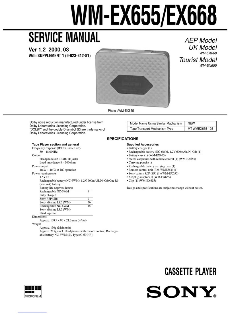
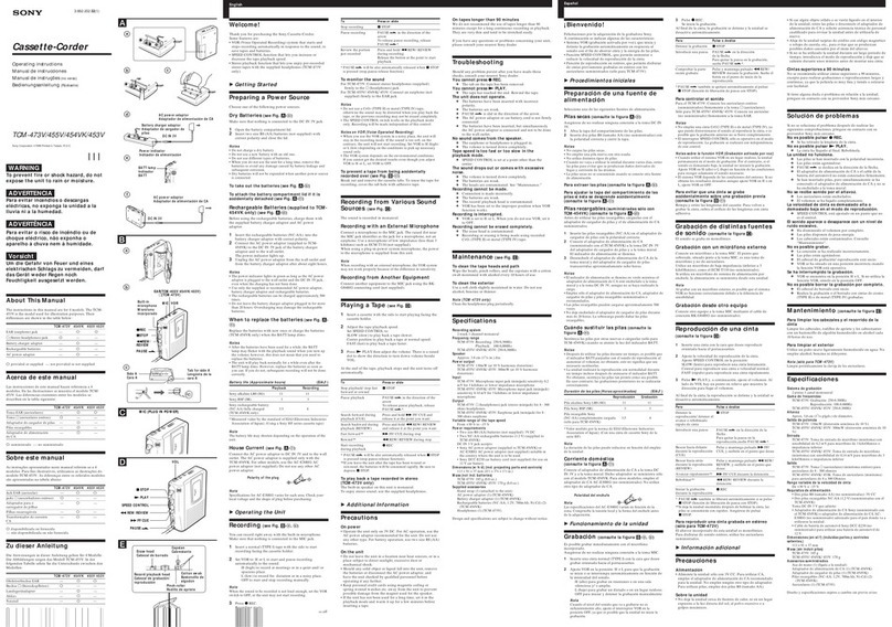
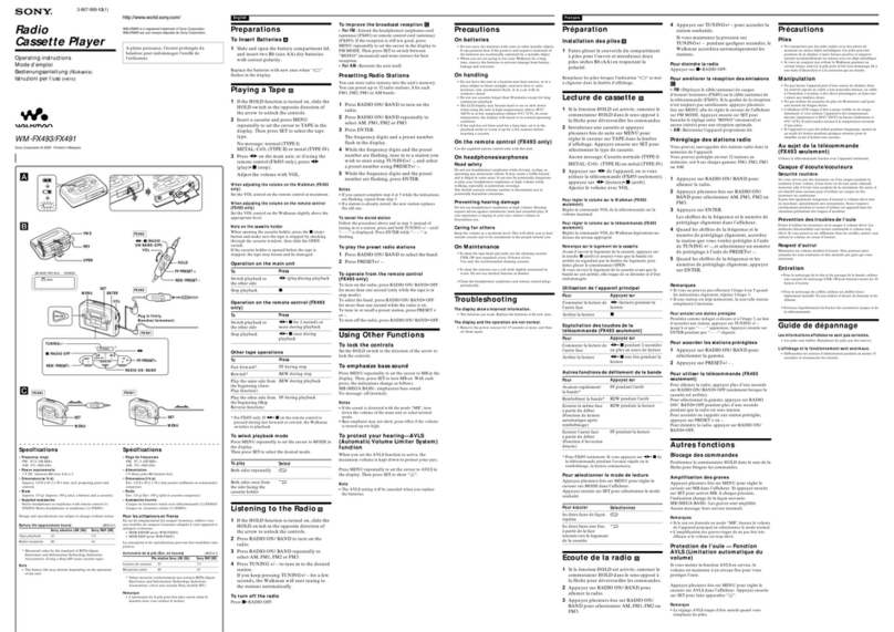
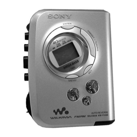
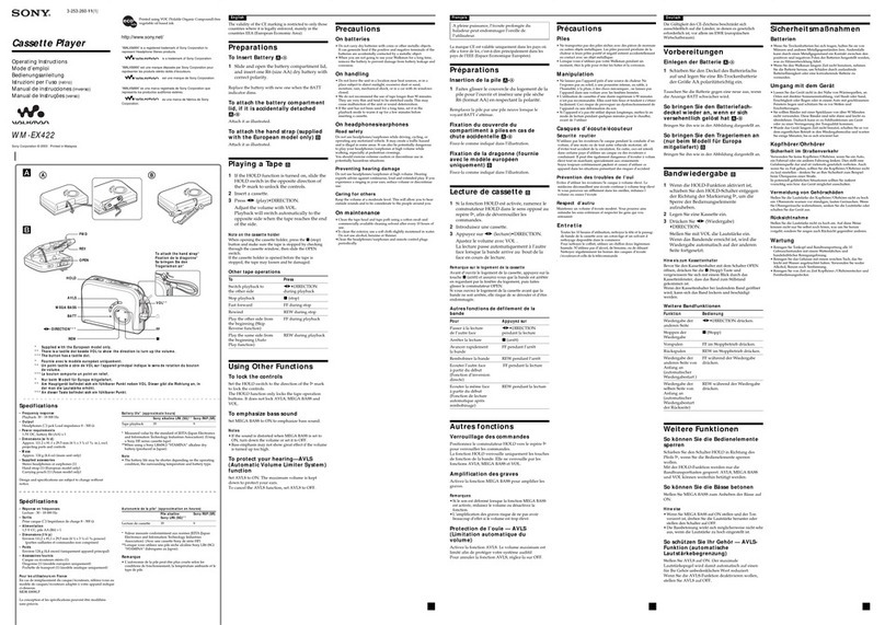
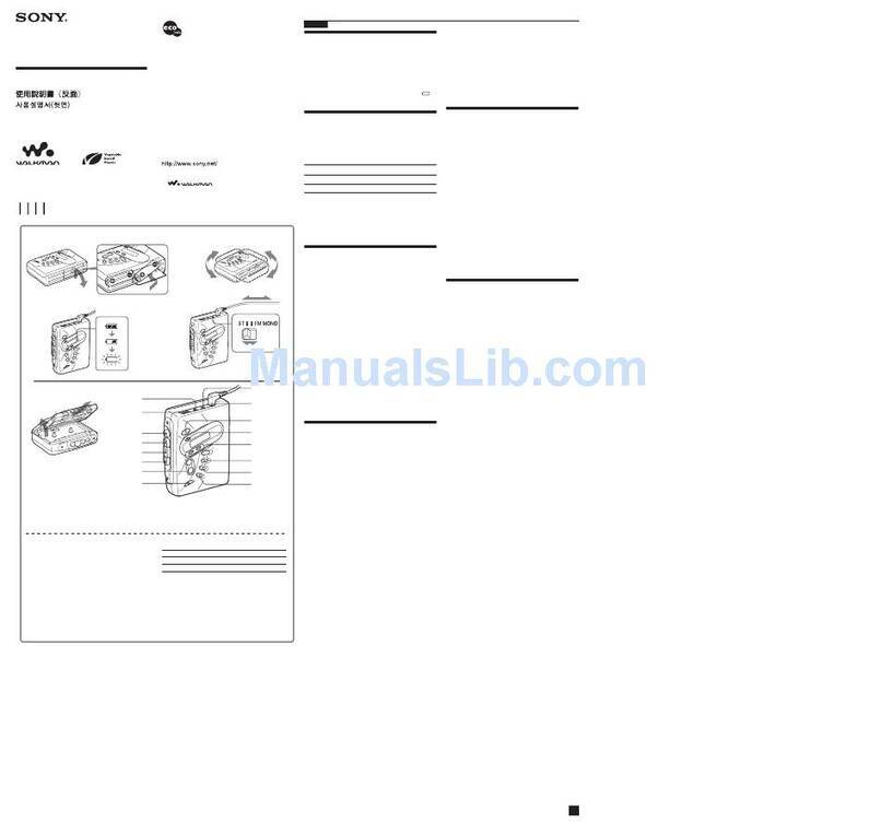
Sony Walkman WM-EX372 User manual

MICROFILM
SERVICE MANUAL
CASSETTE PLAYER
AEP Model
E Model
TC-K6/K7
Model Name Using Similar Mechanism NEW
Tape Transport Mechanism Type MT-WMEX372-114
SPECIFICATIONS
WM-EX372
Dolby noise reduction manufactured under license
from Dolby Laboratories Licensing Corporation.
“DOLBY”and the double-D symbol aare trade-
marks of Dolby Laboratories Licensing Corporation.
Ver 1.2 1999.03
With SUPPLEMENT 1
(9-923-319-81)
With SUPPLEMENT 2
(9-923-319-82)

– 2 –
TABLE OF CONTENTS
1. GENERAL ................................................................... 3
2. DISASSEMBLY ......................................................... 4
3. MECHANICAL ADJUSTMENTS....................... 8
4. ELECTRICAL ADJUSTMENTS......................... 8
5. DIAGRAMS
5-1. Block Diagram ................................................................ 9
5-2. Printed Wiring Board ...................................................... 11
5-3. Schematic Diagram ......................................................... 13
6. EXPLODED VIEWS................................................ 16
7. ELECTRICAL PARTS LIST ............................... 19
Flexible Circuit Board Repairing
• Keep the temperature of the soldering iron around 270 ˚C dur-
ing repairing.
• Do not touch the soldering iron on the same conductor of the
circuit board (within 3 times).
• Be careful not to apply force on the conductor when soldering
or unsoldering.
Notes on chip component replacement
• Never reuse a disconnected chip component.
• Notice that the minus side of a tantalum capacitor may be dam-
aged by heat.

– 3 –
SECTION 1
GENERAL This section is extracted from
instruction manual.

– 4 –
2
Insert the precision screw driver (1.4 mm flat-blade) in to the slit at claw
A
and release the claw.
3
Remove the cabinet (rear) ass’y.(Release all claw
B
to
N
in alphabetical order.)
Note: Follow the disassembly procedure in the numerical order given.
SECTION 2
DISASSEMBLY
CABINET (REAR) ASS’Y
•This set can be disassembled in the order shown below.
CABINET (REAR) ASS’Y MECHANISM DECK
(MT-WMEX372-114) BELT
MAGNETIC HEAD
(HP901)
MOTO
R
(M901)
MEGA BASS UNIT (DOLBY)
MAIN BOARD
CASSETTE HOLDER ASS’Y
SET
1
screw (B1.7
×
9)
1
screw (B1.7
×
9)
K
L
M
NB
C
D
E
F
G
H
I
J
cassette holder
cabinet (rear) ass’
y
A

– 5 –
MAIN BOARD, MECHANISM DECK (MT-WMEX372-114)
BELT, MOTOR (M901), MAGNETIC HEAD (HP901)
6
main board
3
head flexible board
(CN301)
8
Remove the mechanism
deck (MT-WMEX372-114)
to direction of the arrow.
7
claw
7
claw
5
two claws
1
Remove four solders of
motor lead (M901).
4
toothed lock (WH) scre
w
(M1.4)
2
flexible board (CN302)
1
belt
3
motor (M901)
2
two special head screw
s
(M1.4)
4
two screws
5
magnetic head
(HP901)

– 6 –
CASSETTE HOLDER ASS’Y
NOTE FOR INSTALLATION
Note: Follow the assembly procedure in the numerical order given.
•SPRING (TORSION)
A
B
1
flexible board
(CN302)
3
portion
B
to release
the hinge plate.
5
spring (torsion)
4
cassette holder ass’y
2
Insert a precision screwdriver (1.4 mm flat-blade)
vertically in to portion
A
to release the hinge plate.
3
cassette holder ass’y
1
Attach the spring (torsion) as
shown in the figure.
2
Insert the spring (torsion) in the
ditch to direction of the arrow
A
.
A

– 7 –
MEGA BASS UNIT (DOLBY)
4
mega bass unit (dolby)
1
two knobs (rotary)
5
flexible board
2
claw
3
Remove five claws as
move the mega bass
unit (dolby) to direction
of the arrow
A
.
three claws
claw claw
A

– 8 –
Meter reading
more than 30 g
(more than 0.41 oz)
Torque meter
CQ-403A
CQ-403R
Meter reading
20 – 42 g•cm
(0.28 – 0.58 oz•inch)
less than 2 g•cm
(less than 0.03 oz•inch)
20 – 42 g•cm
(0.28 – 0.58 oz•inch)
less than 2 g•cm
(less than 0.03 oz•inch)
more than 50 g•cm
(more than 0.69 oz•inch)
Torque meter
CQ-102C
CQ-102RC
CQ-201B
3-1. MECHANICAL ADJUSTMENTS
Precaution
1. Clean the following parts with a denatured-alcohol-moistened
swab:playback head pinch roller
capstan rubber belt
2. Demagnetize the playback head with a head demagnetizer.
3. Do not use a magnetized screwdriver for the adjustments.
4. After the adjustments, apply suitable locking compound to the
parts adjusted.
5. The adjustments should be performed with the rated power
supply voltage (2.5 V) unless otherwise noted.
Torque Measurement
SECTION 3
MECHANICAL ADJUSTMENTS
Tape Pulling Force Measurement
SECTION 4
ELECTRICAL ADJUSTMENTS
Precaution
•Supplied voltage: 2.5 V
•Switch and control position
NORM CrO2/METAL switch: NORM
VOLUME CONTROL: maximum
TONE CONTROL HIGH and LOW: mechanical center
AVLS switch: NORM
MEGA BASS switch: OFF
DOLBY NR switch: OFF
Test tape
0 dB = 0.775 V
Tape Speed Adjustment
Procedure:
Type Signal Used for
WS-48A 3 kHz, 0 dB Tape Speed Adjustment
+
–
frequency counter
set
2
jack
16
Ω
test tape
WS-48A
(3 kHz, 0 dB)
1. Playback WS-48A (tape end part) in the REV mode and adjust
RV601 so that the frequency counter reading becomes 2,980
Hz ± 1%.
2. Playback WS-48A (tape top part) in the FWD mode and check
that the frequency counter reading becomes 2,980 ± 45 Hz.
3. PlaybackWS-48A (tape end part) in the FWD mode and check
that the frequency counter reading recomes 2,980 ± 45 Hz.
4. Playback WS-48A (tape top part) in the REV mode and check
that the frequency counter reading becomes 2,980 ± 45 Hz.
Adjustment Location:
RV601 label (model)
Mode
FWD
FWD
Back Tension
REV
REV
Back Tension
FF, REW
Mode
FWD
REV

WM-EX372
– 13 – – 14 –
5-3. SCHEMATIC DIAGRAM • See page 15 for IC Block Diagrams.
Note on Schematic Diagram:
• All capacitors are in µF unless otherwise noted. pF: µµF
50 WV or less are not indicated except for electrolytics
and tantalums.
• All resistors are in Ωand 1/4W or less unless otherwise
specified.
•C: panel designation.
•U: B+ Line.
•H: adjustment for repair.
• Total current is measured with no cassette installed.
• Power voltage is dc 3 V and fed with regulated dc power
supply from external power voltage jack.
• Voltages and waveforms are dc with respect to ground in
playback mode.
no mark : PB (FWD)
( ) : PB (REV)
• Voltages aretakenwith aVOM(Input impedance10 MΩ).
Voltage variations may be noted due to normal produc-
tion tolerances.
• Waveforms are taken with a oscilloscope.
Voltage variations may be noted due to normal produc-
tion tolerances.
• Circled numbers refer to waveforms.
• Signal path.
E: PB
•Waveforms
1IC601 1(WB)
100 mV/DIV, 2 ms/DIV 2IC601 !¡ (OSC)
10 mV/DIV, 1 ms/DIV
290 mVp-p
4.5 ms
40 mVp-p
1.5 ms
Ver 1.2 1999. 03

WM-EX372
– 15 – – 16 –
SECTION 6
EXPLODED VIEWS
• Items marked “*” are not stocked since they
are seldom required for routine service. Some
delay should be anticipated when ordering
these items.
• The mechanical parts with no reference num-
ber in the exploded views are not supplied.
• Accessories and packing materials are given
in the last of the electrical parts list.
NOTE:
• -XX and -X mean standardized parts, so they
may have some difference from the original
one.
• Color Indication of Appearance Parts
Example:
KNOB, BALANCE (WHITE) . . . (RED)
↑↑
Parts Color Cabinet's Color
Ref. No. Part No. Description Remark Ref. No. Part No. Description Remark
(1) CASSETTE HOLDER SECTION
•IC Block Diagrams
IC331 NJM2185AV-TE2
IC601 LB1979V-TLM
1 1-475-441-11 MEGA BASS UNIT (DOLBY)
2 3-019-937-01 ACTUATOR (B)
3 3-019-938-01 ACTUATOR (C)
4 3-007-012-01 SPRING (TORSION)
5 X-3375-841-1 KNOB ASSY, DOLBY
6 3-019-857-11 KNOB (ROTARY)
7 X-3375-840-1 KNOB ASSY, MEGABASS
8 3-019-849-01 HOLDER, CASSETTE (for BLACK)
8 3-019-849-11 HOLDER, CASSETTE (for BLUE)
45
6
6
7
8
2
1
3

– 17 –
Ref. No. Part No. Description Remark Ref. No. Part No. Description Remark
(2) CABINET SECTION
51 3-015-285-01 SCREW (M1.4), TOOTHED LOCK (WH)
52 A-3021-042-A MAIN BOARD, COMPLETE (EXCEPT French)
52 A-3021-043-A MAIN BOARD, COMPLETE (French)
53 3-022-698-01 TERMINAL (–), BATTERY
54 3-019-862-01 TERMINAL (+), BATTERY
55 3-019-859-01 BUTTON (STOP) (p)
56 3-019-860-01 BUTTON (FF) (0)
57 3-019-858-01 BUTTON (PLAY) (()
58 3-019-861-01 BUTTON (REW) ())
59 3-932-037-01 SPRING (CASSETTE)
60 3-019-851-01 CABINET (FRONT)
61 3-022-581-01 PLATE, LIGHT GUIDE
62 3-019-864-01 CABINET (REAR)
63 3-019-856-11 LID, BATTERY CASE
64 3-318-203-92 SCREW (B1.7X9), TAPPING
65 3-016-420-01 STOPPER (L)
66 3-022-580-01 SHEET (INSULATING)
60
59
58
MT-WMEX372-114
57
56
55 54
53
64
63
62
61
52
51
66
65

– 18 –
Ref. No. Part No. Description Remark Ref. No. Part No. Description Remark
(3) MECHANISM DECK SECTION (MT-WMEX372-114)
101 X-3369-749-1 PINCH LEVER (N) ASSY
102 3-920-996-01 SPRING (PINCH N)
103 X-3369-747-1 WHEEL ASSY, CAPSTAN
104 3-704-197-71 SCREW (M1.4)
105 3-921-042-01 GEAR (REEL)
106 3-921-797-01 WASHER
107 3-921-003-01 BEARING
108 3-920-993-01 SPRING (NR)
109 X-3372-960-1 CHASSIS (COMP) ASSY
110 3-938-657-11 BELT
111 3-015-436-01 SPRING (STOP)
112 3-013-142-01 SPRING (FR-CP)
113 3-921-053-01 LEVER, D SELECTION
114 3-921-043-01 GEAR (D)
115 X-3369-752-1 CLUTCH ASSY
116 3-920-999-01 GEAR (A)
117 3-921-050-01 GEAR (B)
118 3-920-990-01 SPRING (UD), COMPRESSION
119 3-921-335-01 WASHER, LEVER
120 3-923-530-01 SLEEVE (M)
121 3-728-091-01 WASHER, STOPPER
122 3-921-052-01 LEVER (A), DETECTION
123 3-920-994-11 SPRING (D SELECTION)
124 3-929-419-01 LEVER (BR), DETECTION
125 3-938-628-01 SPRING (PLAY-CP)
126 3-703-816-31 SCREW (M1.4), SPECIAL HEAD
127 3-921-023-01 LEVER, M SELECTION
128 X-3369-748-1 PINCH LEVER (R) ASSY
129 3-920-997-01 SPRING (PINCH R)
130 3-933-324-01 SPRING (FR LEVER)
131 3-016-989-01 SPRING (SW-CP)
HP901 1-668-622-11 MAGNETIC HEAD (PLAYBACK)
M901 1-763-073-11 MOTOR (CAPSTAN/REEL)
112
131
110
not suplied
103
111
103
108
102
101
106
107
113
104
128
129
105
126
127
107
105
106
124
123
114
130
115
119
121
120
118
122
117
116
125
109
M901
HP901
not suplied

– 19 –
SECTION 7
ELECTRICAL PARTS LIST
Ref. No. Part No. Description Remark
NOTE:
• Due to standardization, replacements in the
parts list may be different from the parts speci-
fied in the diagrams or the components used
on the set.
• -XX and -X mean standardized parts, so they
may have some difference from the original
one.
• RESISTORS
All resistors are in ohms.
METAL: Metal-film resistor.
METAL OXIDE: Metal oxide-film resistor.
F: nonflammable
• Abbreviation
9E: No indication of country of origin.
• Items marked “*” are not stocked since they
are seldom required for routine service.
Some delay should be anticipated when order-
ing these items.
• SEMICONDUCTORS
In each case, u: µ, for example:
uA. . : µA. . uPA. . : µPA. .
uPB. . : µPB. . uPC. . : µPC. .
uPD. . : µPD. .
• CAPACITORS
uF: µF
• COILS
uH: µH
Ref. No. Part No. Description Remark
MAIN
When indicating parts by reference
number, please include the board.
A-3021-042-A MAIN BOARD, COMPLETE (EXCEPT French)
A-3021-043-A MAIN BOARD, COMPLETE (French)
*********************
3-019-862-01 TERMINAL (+), BATTERY
3-022-698-01 TERMINAL (–), BATTERY
< CAPACITOR >
C101 1-163-007-11 CERAMIC CHIP 680PF 10% 50V
C102 1-163-007-11 CERAMIC CHIP 680PF 10% 50V
C103 1-163-017-00 CERAMIC CHIP 0.0047uF 5% 50V
C104 1-126-157-11 ELECT 10uF 20% 16V
C106 1-164-161-11 CERAMIC CHIP 0.0022uF 10% 100V
C107 1-164-346-11 CERAMIC CHIP 1uF 16V
C108 1-163-009-11 CERAMIC CHIP 0.001uF 10% 50V
C131 1-164-346-11 CERAMIC CHIP 1uF 16V
C132 1-164-505-11 CERAMIC CHIP 2.2uF 16V
C133 1-164-489-11 CERAMIC CHIP 0.22uF 10% 16V
C134 1-164-346-11 CERAMIC CHIP 1uF 16V
C201 1-163-007-11 CERAMIC CHIP 680PF 10% 50V
C202 1-163-007-11 CERAMIC CHIP 680PF 10% 50V
C203 1-163-017-00 CERAMIC CHIP 0.0047uF 5% 50V
C204 1-126-157-11 ELECT 10uF 20% 16V
C206 1-164-161-11 CERAMIC CHIP 0.0022uF 10% 100V
C207 1-164-346-11 CERAMIC CHIP 1uF 16V
C208 1-163-009-11 CERAMIC CHIP 0.001uF 10% 50V
C231 1-164-346-11 CERAMIC CHIP 1uF 16V
C232 1-164-505-11 CERAMIC CHIP 2.2uF 16V
C233 1-164-489-11 CERAMIC CHIP 0.22uF 10% 16V
C234 1-164-346-11 CERAMIC CHIP 1uF 16V
C301 1-163-009-11 CERAMIC CHIP 0.001uF 10% 50V
C302 1-163-038-00 CERAMIC CHIP 0.1uF 25V
C303 1-126-153-11 ELECT 22uF 20% 6.3V
C304 1-164-222-11 CERAMIC CHIP 0.22uF 25V
C305 1-126-176-11 ELECT 220uF 20% 10V
C306 1-164-346-11 CERAMIC CHIP 1uF 16V
C307 1-163-038-00 CERAMIC CHIP 0.1uF 25V
C308 1-126-162-11 ELECT 3.3uF 20% 50V
C309 1-164-004-11 CERAMIC CHIP 0.1uF 10% 25V
C310 1-164-346-11 CERAMIC CHIP 1uF 16V
C311 1-164-346-11 CERAMIC CHIP 1uF 16V
C312 1-164-004-11 CERAMIC CHIP 0.1uF 10% 25V
C314 1-164-346-11 CERAMIC CHIP 1uF 16V
C315 1-126-153-11 ELECT 22uF 20% 6.3V
C317 1-163-009-11 CERAMIC CHIP 0.001uF 10% 50V
C318 1-163-009-11 CERAMIC CHIP 0.001uF 10% 50V
C319 1-163-009-11 CERAMIC CHIP 0.001uF 10% 50V
C322 1-163-117-00 CERAMIC CHIP 100PF 5% 50V
C323 1-163-009-11 CERAMIC CHIP 0.001uF 10% 50V
C324 1-163-038-00 CERAMIC CHIP 0.1uF 25V
C331 1-164-346-11 CERAMIC CHIP 1uF 16V
C332 1-164-005-11 CERAMIC CHIP 0.47uF 25V
C333 1-163-009-11 CERAMIC CHIP 0.001uF 10% 50V
C334 1-126-157-11 ELECT 10uF 20% 16V
C601 1-164-344-11 CERAMIC CHIP 0.068uF 10% 25V
C602 1-107-823-11 CERAMIC CHIP 0.47uF 10% 16V
C603 1-126-176-11 ELECT 220uF 20% 10V
C605 1-164-344-11 CERAMIC CHIP 0.068uF 10% 25V
C606 1-164-344-11 CERAMIC CHIP 0.068uF 10% 25V
C607 1-164-489-11 CERAMIC CHIP 0.22uF 10% 16V
C608 1-163-809-11 CERAMIC CHIP 0.047uF 10% 25V
C609 1-164-505-11 CERAMIC CHIP 2.2uF 16V
C610 1-107-823-11 CERAMIC CHIP 0.47uF 10% 16V
< CONNECTOR >
CN301 1-750-346-21 CONNECTOR, FFC/EPC (ZIF) 6P
*CN302 1-784-527-11 CONNECTOR, FPC (ZIF) 9P
< DIODE >
D150 8-719-067-62 LED LNJ210C6AOSO (BATT)
< IC >
IC301 8-759-332-69 IC LA4585M-TLM
IC331 8-759-488-80 IC NJM2185AV-TE2
IC601 8-759-447-73 IC LB1979V-TLM
< JACK >
J301 1-750-061-11 JACK,DC (POLARITY UNIFIED TYPE) (DC IN 3V)
J302 1-565-287-11 JACK (2)
< JUMPER RESISTOR >
JR201 1-216-295-00 SHORT (CHIP) 0
JR202 1-216-295-00 SHORT (CHIP) 0
JR203 1-216-295-00 SHORT (CHIP) 0
JR301 1-216-296-00 SHORT (CHIP) 0

– 20 –
Ref. No. Part No. Description Remark Ref. No. Part No. Description Remark
JR302 1-216-296-00 SHORT (CHIP) 0
JR303 1-216-296-00 SHORT (CHIP) 0
JR304 1-216-296-00 SHORT (CHIP) 0
JR305 1-216-296-00 SHORT (CHIP) 0
JR306 1-216-296-00 SHORT (CHIP) 0
JR307 1-216-296-00 SHORT (CHIP) 0
JR308 1-216-296-00 SHORT (CHIP) 0
JR309 1-216-296-00 SHORT (CHIP) 0
JR310 1-216-296-00 SHORT (CHIP) 0
JR311 1-216-296-00 SHORT (CHIP) 0
JR313 1-216-296-00 SHORT (CHIP) 0
JR314 1-216-296-00 SHORT (CHIP) 0
JR315 1-216-296-00 SHORT (CHIP) 0
JR316 1-216-296-00 SHORT (CHIP) 0
JR317 1-216-296-00 SHORT (CHIP) 0
JR318 1-216-296-00 SHORT (CHIP) 0
JR319 1-216-296-00 SHORT (CHIP) 0
JR320 1-216-296-00 SHORT (CHIP) 0
JR321 1-216-296-00 SHORT (CHIP) 0
JR322 1-216-296-00 SHORT (CHIP) 0
JR323 1-216-296-00 SHORT (CHIP) 0
JR324 1-216-296-00 SHORT (CHIP) 0
JR325 1-216-296-00 SHORT (CHIP) 0
< RESISTOR >
R101 1-216-089-00 RES,CHIP 47K 5% 1/10W
R102 1-216-089-00 RES,CHIP 47K 5% 1/10W
R103 1-216-079-00 METAL CHIP 18K 5% 1/10W
R104 1-216-075-00 METAL CHIP 12K 5% 1/10W
R105 1-216-117-00 METAL CHIP 680K 5% 1/10W
R106 1-216-046-00 METAL CHIP 750 5% 1/10W
R107 1-216-311-00 METAL CHIP 6.8 5% 1/10W
(EXCEPT FRENCH)
R107 1-216-013-00 METAL CHIP 33 5% 1/10W
(FRENCH)
R109 1-216-095-00 METAL CHIP 82K 5% 1/10W
R110 1-216-049-11 RES,CHIP 1K 5% 1/10W
R111 1-216-174-00 RES,CHIP 100 5% 1/8W
R150 1-216-053-00 METAL CHIP 1.5K 5% 1/10W
R201 1-216-089-00 RES,CHIP 47K 5% 1/10W
R202 1-216-089-00 RES,CHIP 47K 5% 1/10W
R203 1-216-079-00 METAL CHIP 18K 5% 1/10W
R204 1-216-075-00 METAL CHIP 12K 5% 1/10W
R205 1-216-117-00 METAL CHIP 680K 5% 1/10W
R206 1-216-046-00 METAL CHIP 750 5% 1/10W
R207 1-216-311-00 METAL CHIP 6.8 5% 1/10W
(EXCEPT FRENCH)
R207 1-216-013-00 METAL CHIP 33 5% 1/10W
(FRENCH)
R209 1-216-095-00 METAL CHIP 82K 5% 1/10W
R210 1-216-049-11 RES,CHIP 1K 5% 1/10W
R211 1-216-025-00 RES,CHIP 100 5% 1/10W
R301 1-216-049-11 RES,CHIP 1K 5% 1/10W
R305 1-216-081-00 METAL CHIP 22K 5% 1/10W
R306 1-216-057-00 METAL CHIP 2.2K 5% 1/10W
R309 1-216-113-00 METAL CHIP 470K 5% 1/10W
R324 1-216-298-00 METAL CHIP 2.2 5% 1/10W
R331 1-216-001-00 METAL CHIP 10 5% 1/10W
R332 1-216-081-00 METAL CHIP 22K 5% 1/10W
R333 1-216-688-11 METAL CHIP 36K 0.5% 1/10W
R601 1-216-121-00 RES,CHIP 1M 5% 1/10W
R602 1-216-121-00 RES,CHIP 1M 5% 1/10W
R603 1-216-121-00 RES,CHIP 1M 5% 1/10W
R604 1-216-073-00 METAL CHIP 10K 5% 1/10W
R605 1-216-049-11 RES,CHIP 1K 5% 1/10W
R606 1-216-097-00 RES,CHIP 100K 5% 1/10W
R607 1-216-073-00 METAL CHIP 10K 5% 1/10W
R608 1-216-049-11 RES,CHIP 1K 5% 1/10W
< VARIABLE RESISTOR >
RV301 1-225-544-11 RES, VAR, CARBON 10K/10K (∑VOLUME)
RV601 1-238-663-11 RES, ADJ, CARBON 4.7K
< SWITCH >
S301 1-762-302-11 SWITCH, PUSH (1 KEY) (FWD/REV)
S302 1-762-917-11 SWITCH, DETECTION (SMALL TYPE) (POWER)
S303 1-692-298-11 SWITCH, SLIDE (TAPE SELECTOR)
(NORM, CrO2/METAL)
S305 1-692-298-11 SWITCH, SLIDE (AVLS) (NORM, LIMIT)
< THERMISTOR >
TH601 1-810-794-11 THERMISTOR, POSITIVE (3.3k)
************************************************************
MISCELLANEOUS
***************
1 1-475-441-11 MEGA BASS UNIT (DOLBY)
HP901 1-668-622-11 MAGNETIC HEAD (PLAYBACK)
M901 1-763-073-11 MOTOR (CAPSTAN/REEL)
************************************************************
ACCESSORIES & PACKING MATERIALS
********************************
3-020-998-01 CLIP, BELT
3-862-076-11 MANUAL, INSTRUCTION (ENGLISH, FRENCH)
(East European)
3-862-076-21 MANUAL, INSTRUCTION (ENGLISH, GERMAN,
SPANISH, DUTCH, SWEDISH, ITALIAN,
PORTUGUESE, DANISH) (AEP)
3-862-076-31 MANUAL, INSTRUCTION (FRENCH)
(AEP, French)
3-862-076-41 MANUAL, INSTRUCTION
(GERMAN, POLISH, RUSSIAN, HUNGARIAN,
CZECK, GREEK, TURKISH) (East European)
3-862-076-51 MANUAL, INSTRUCTION
(ENGLISH, CHINESE, KOREAN) (E)
3-862-076-61 MANUAL, INSTRUCTION
(SPANISH, PORTUGUESE) (9E)
8-953-224-90 HEADPHONE MDR-E802LP SET
MAIN
WM-EX372
Sony Corporation
Personal A&V Products Company
9-923-319-11
98B0568-1
Printed in Japan © 1998. 2
Published by Quality Engineering Dept.
(Shibaura)
Ver 1.2 1999. 03

SERVICE MANUAL
WM-EX372
SUPPLEMENT-1
File this supplement with the service manual.
AEP Model
E Model
Chinese Model
Subject: Addition of Chinese Model
Addition of Chinese Model
Chinese Model have been added.
This is the same as E model which is not described in this supplement-1
Refer to WM-EX372 original service manual (9-923-319-11) for other information.
ACCESSORIES & PACKING MATERIAL
Page E model Chinese model
Ref. No. Part No. Description Remark
3-862-076-71 MANUAL, INSTRUCTION
(ENGLISH, CHINESE) (Chinese)
Ref. No. Part No. Description Remark
3-862-076-61 MANUAL, INSTRUCTION
(ENGLISH, CHINESE, KOREAN) (E)
20
Sony Corporation
Personal A&V Products Company
98E05045-1D
Printed in Japan © 1998. 5
Published by Quality Engineering Dept.
(Shibaura)9-923-319-81
1998. 05

SERVICE MANUAL
WM-EX372
SUPPLEMENT-2
File this supplement with the service manual.
AEP Model
E Model
Chinese Model
Tourist Model
Subject: Addition ofTourist Model
Addition ofTourist Model
Tourist Model have been added.
This is the same as E model which is not described in this supplement-2
Refer to WM-EX372 original service manual (9-923-319-∏) for other information.
ACCESSORIES & PACKING MATERIAL
Page E model Tourist model
Ref. No. Part No. Description Remark
3-864-071-11 MANUAL, INSTRUCTION
(ENGLISH, CHINESE, KOREAN, RUSSIAN)
(Tourist)
Ref. No. Part No. Description Remark
3-862-076-61 MANUAL, INSTRUCTION
(ENGLISH, CHINESE, KOREAN) (E)
20
Sony Corporation
Personal A&V Products Company
98J05031-1D
Printed in Japan © 1998. 10
Published by Quality Engineering Dept.
(Shibaura)9-923-319-82
1998. 10
Other manuals for Walkman WM-EX372
2
Table of contents
Other Sony Cassette Player manuals

Sony
Sony WM-EX50 User manual

Sony
Sony Walkman WM-EX525 User manual

Sony
Sony CFD-758 User manual

Sony
Sony WM-FX413 User manual

Sony
Sony CFS-B7SMK2 User manual

Sony
Sony Walkman WM-FX495 User manual

Sony
Sony Walkman WM-FX661 User manual

Sony
Sony SVT-N72P User manual

Sony
Sony CFD-G555CP User manual

Sony
Sony Walkman WM-EX674 User manual

Sony
Sony TCM-40DV User manual

Sony
Sony Sports Walkman WM-FS593 User manual

Sony
Sony TC-TX5 User manual

Sony
Sony Pressman TCM-929 User manual

Sony
Sony SLV-ED100ME User manual

Sony
Sony Pressman TCM-929 User manual

Sony
Sony WM-AF65 User manual

Sony
Sony 453V User manual

Sony
Sony Walkman WM-SP1 User manual

Sony
Sony U-matic S VO-6800PS User manual