Working Instructions (mech)
1266-1672 Rev 3
Sony Mobile Communications AB –
2(39)
CONTENTS
1
Exterior Views.................................................................................4
1.1
ST21i, ST21a, ST21i2, ST21a2.............................................................4
2
Tools................................................................................................5
3
Disassembly....................................................................................6
3.1
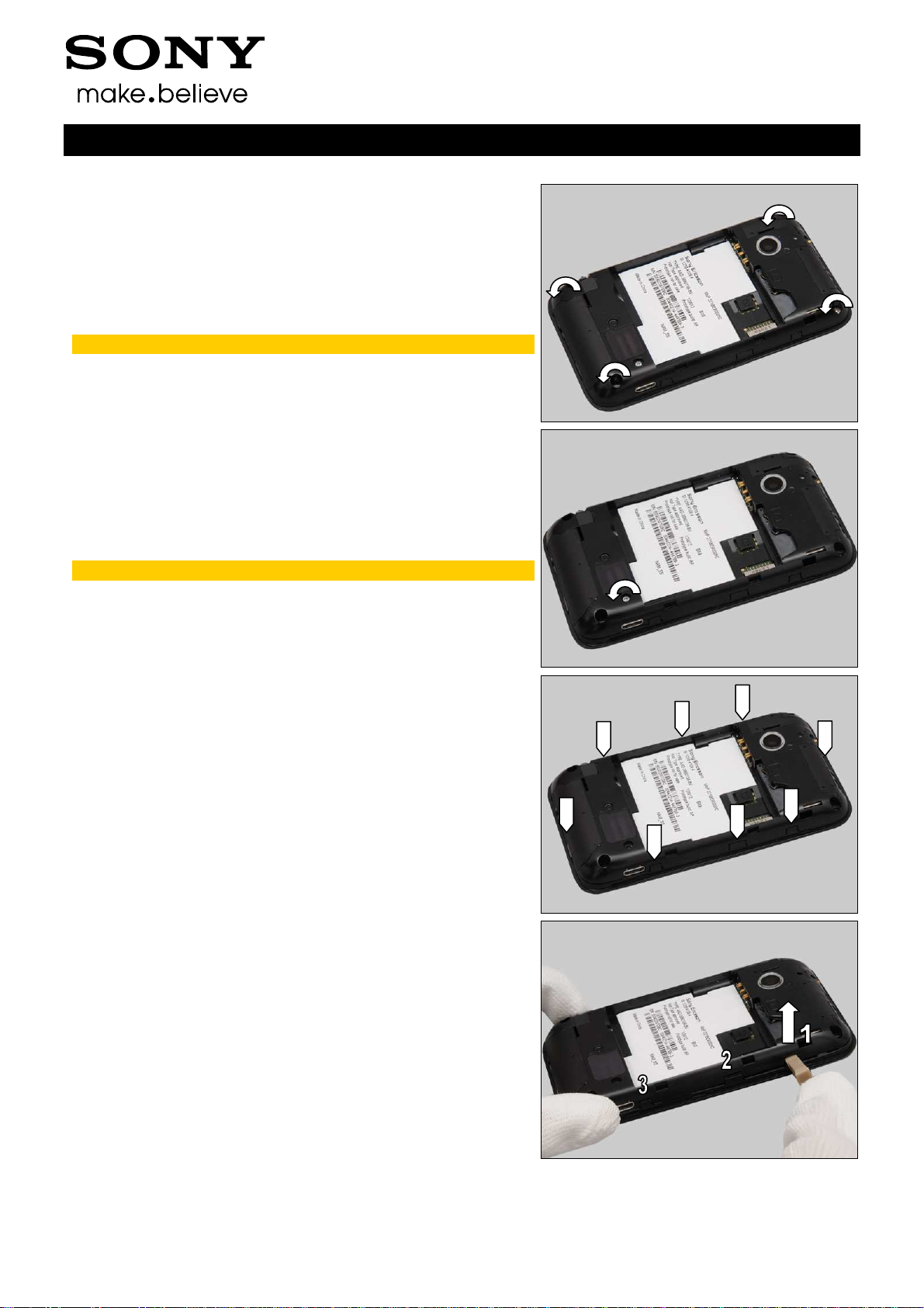
Battery Cover........................................................................................6
3.2
Battery...................................................................................................6
3.3
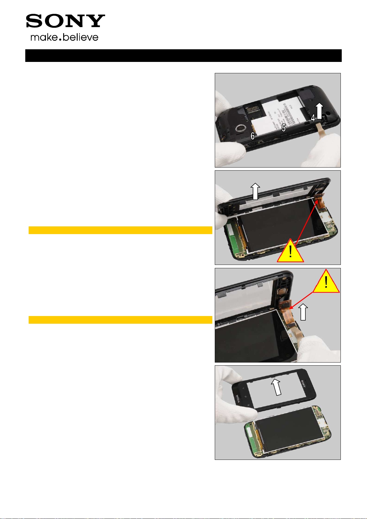
Front Assy ............................................................................................7
3.4
Frame Antenna Assy............................................................................9
3.5
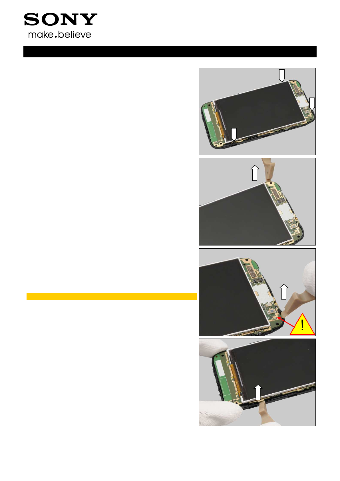
Main PBA & LCD TFT 3.2Inch............................................................10
4
Replacement.................................................................................12
4.1
Battery Cover......................................................................................12
4.2
Front Assy ..........................................................................................12
4.3
Frame Antenna Assy..........................................................................12
4.4
LCD TFT 3.2Inch.................................................................................12
4.5
Audio Jack..........................................................................................13
4.6
Camera................................................................................................14
4.7
Camera Lens.......................................................................................16
4.8
Conductive LCM Gasket....................................................................17
4.9
Conductive TP Gasket.......................................................................18
4.10
Core Unit Label...................................................................................19
4.11
Loudspeaker.......................................................................................20
4.12
Receiver..............................................................................................21
4.13
RF Switch Mylar .................................................................................22
4.14
Rubber Indicator ................................................................................23
4.15
Shield Can Lid Baseband ..................................................................24
4.16
Shield Can Lid BT ..............................................................................25
4.17
Shield Can Lid RF ..............................................................................26
4.18
Speaker Gasket..................................................................................27
4.19
Speaker Mesh.....................................................................................28
4.20
TP Protection Film .............................................................................29
4.21
Water Indicator (on board).................................................................30
4.22
Water Indicator (on Audio Jack) .......................................................31
4.23
Board Swap - Replacement...............................................................32
4.24
Board Swap – Change Label.............................................................32
4.25
Board Swap – Customize of Software..............................................32
5
Reassembly...................................................................................33
5.1
LCD TFT 3.2Inch & Main PBA............................................................33
5.2
Frame Antenna Assy..........................................................................34
5.3
Front Assy ..........................................................................................35