1-1
SECTION 1
GENERAL This section is extracted from instruction
manual (3-083-624-11).
DVP-LS500
6
About this Manual
Instructions in this manual describe the
controls on the remote. You can also use the
controls on the player if they have the same
or similar names as those on the remote.
DVD may be used as a general term for
DVD VIDEOs, DVD-RWs/DVD-Rs, and
DVD+RWs/DVD+Rs.
Displays on the screen are slightly different
depending upon where the model is sold.
The meaning of the icons used in this
manual is described below:
*MP3 (MPEG1 Audio Layer 3) is a standard
format defined by ISO/MPEG which compresses
audio data.
This Player Can Play the
Following Discs
DVD VIDEO and DVD-RW are
trademarks.
Region code
Your player has a region code printed on the
back of the unit and only will play DVD
VIDEO discs (playback only) labelled with
identical region codes. This system is used to
protect copyrights.
DVD VIDEOs labelled willalsoplayon
this player.
If you try to play any other DVD VIDEO, the
message Playback prohibited by area
limitations. will appear on the TV screen.
Depending on the DVD VIDEO, no region
code indication may be labelled even though
playing the DVD VIDEO is prohibited by
area restrictions.
Example of discs that the player
cannot play
The player cannot play the following discs:
All CD-ROMs (including PHOTO CDs)/
CD-Rs/CD-RWs other than those recorded
in the following formats:
music CD format
video CD format
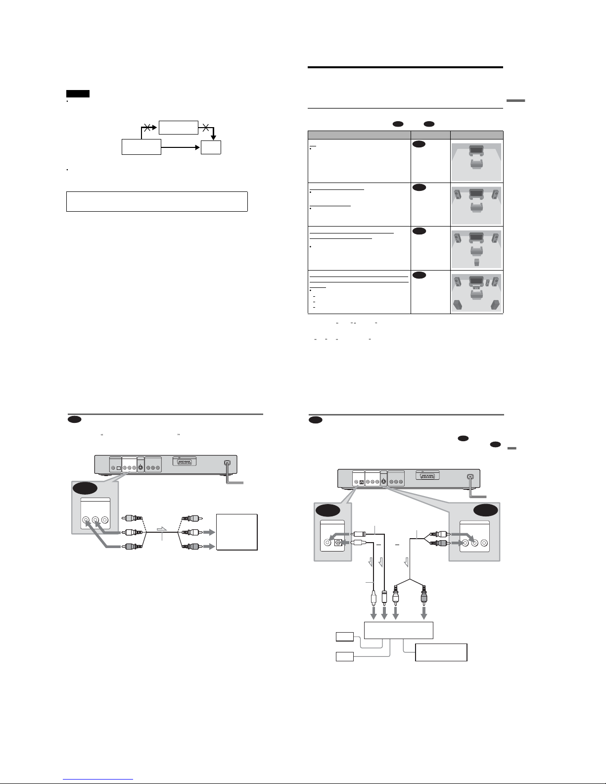
Icon Meaning
Functions available for DVD
VIDEOs and DVD-RWs/
DVD-Rs in video mode or
DVD+RWs/DVD+Rs
Functions available for DVD-
RWs in VR (Video Recording)
mode
Functions available forVIDEO
CDs, Super VCDs or CD-Rs/
CD-RWs in video CD format
or Super VCD format
Functions available for music
CDs or CD-Rs/CD-RWs in
music CD format
Functions available for DATA
CDs (CD-ROMs/CD-Rs/CD-
RWs containing MP3* audio
tracks)
Format of discs
DVD VIDEO
(page 71)
DVD-RW
(page 71)
VIDEO CD
Music CD
ALL
DVP—XXXX
00V 00Hz
00W
NO.
0-000-000-00
X
Region code
7
MP3 format that conforms to ISO9660*
Level 1/Level 2, or its extended format,
Joliet
Data part of CD-Extras
DVD-ROMs
DVD Audio discs
HD layer on Super Audio CDs
*Alogical format of files and folders on CD-
ROMs, defined by ISO (International Standard
Organization).
Also, the player cannot play the following
discs:
A DVD VIDEO with a different region
code.
A disc that has a non-standard shape (e.g.,
card, heart).
A disc with paper or stickers on it.
A disc that has the adhesive of cellophane
tape or a sticker still left on it.
Notes
Notes about DVD-RWs/DVD-Rs, DVD+RWs/
DVD+Rs or CD-Rs/CD-RWs
Some DVD-RWs/DVD-Rs, DVD+RWs/
DVD+Rs, or CD-Rs/CD-RWs cannot be played
on this player due to the recording quality or
physical condition of the disc, or the
characteristics of the recording device and
authoring software.
The disc will not play if it has not been correctly
finalized. Also, images in DVD-RW discs with
CPRM* protection may not be played if they
contain a copy protection signal. Copyright
lock appears on the screen. For more
information, see the operating instructions for the
recording device. Note that discs created in the
Packet Write format cannot be played.
*CPRM(Content Protection for Recordable
Media) is a coding technology that protects the
copyright of images.
Music discs encoded with copyright protection
technologies
This product is designed to playback discs that
conform to the Compact Disc (CD) standard.
Recently, various music discs encoded with
copyright protection technologies are marketed
by some record companies. Please be aware that
among those discs, there are some that do not
conform to the CD standard and may not be
playable by this product.
Note on playback operations of
DVDs and VIDEO CDs
Some playback operations of DVDs and
VIDEO CDs may be intentionally set by
software producers. Since this player plays
DVDs and VIDEO CDs according to the disc
contents the software producers designed,
some playback features may not be available.
Also, refer to the instructions supplied with
the DVDs or VIDEO CDs.
Copyrights
This product incorporates copyright
protection technology that is protected by
method claims of certain U.S. patents, other
intellectual property rights owned by
Macrovision Corporation, and other rights
owners. Use of this copyright protection
technology must be authorized by
Macrovision Corporation, and is intended for
home and other limited viewing uses only
unless otherwise authorized by Macrovision
Corporation. Reverse engineering or
disassembly is prohibited.
Notes about the Discs
Tokeep the disc clean, handle the disc by its
edge. Do not touch the surface.
Do not expose the disc to direct sunlight or
heatsources such as hot air ducts, or leave it
in a car parked in direct sunlight as the
temperature may rise considerably inside
the car.
After playing, store the disc in its case.
Clean the disc with a cleaning cloth.
Wipe the disc from the centre out.
Do not use solvents such as benzine,
thinner,commerciallyavailablecleaners,or
anti-static spray intended for vinyl LPs.
8
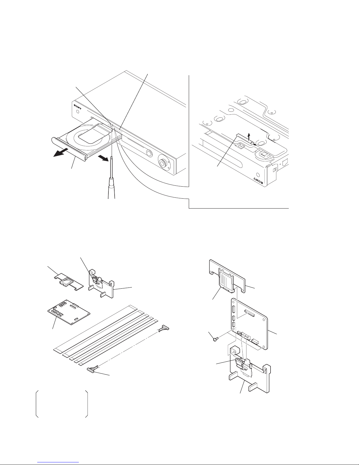
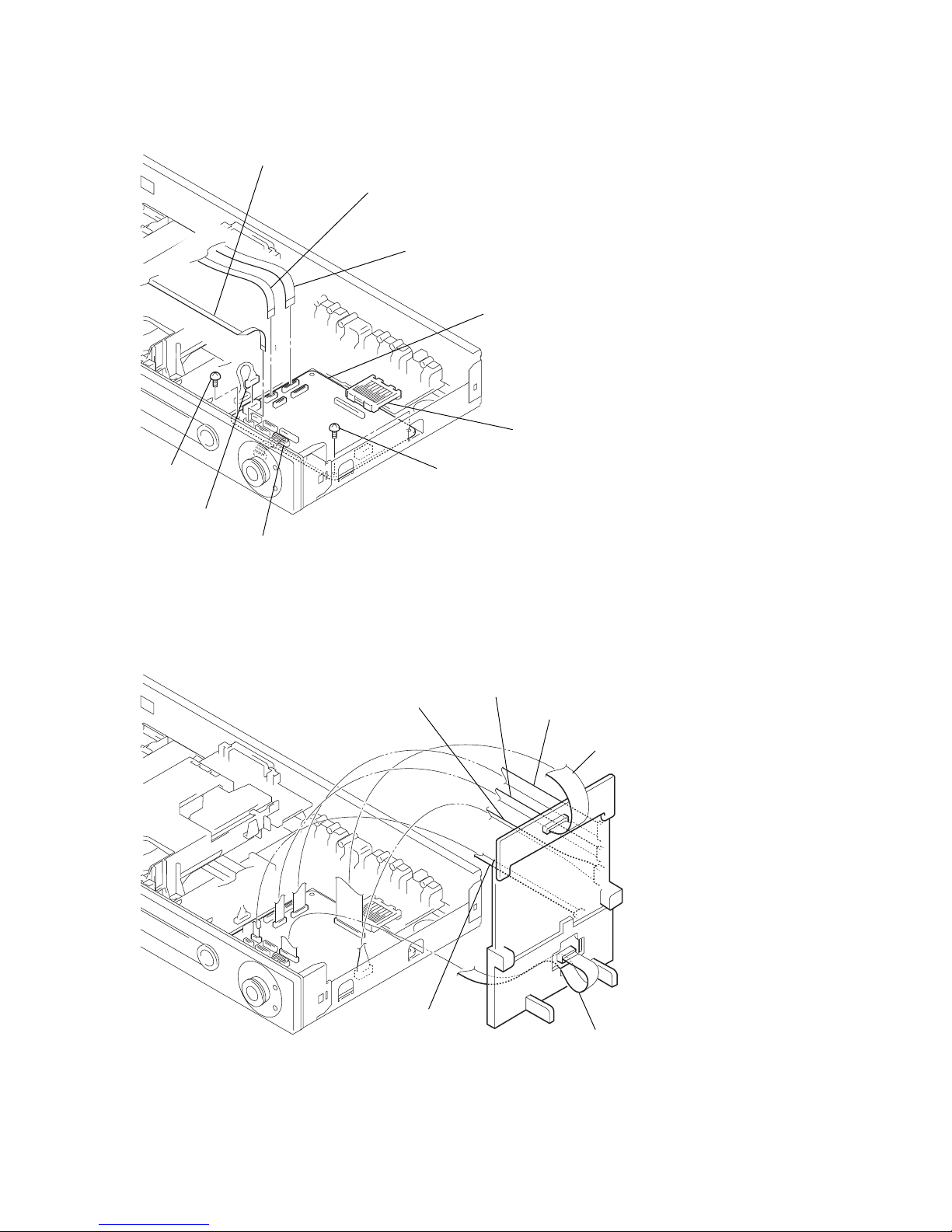
Index to Parts and Controls
For more information, refer to the pages indicated in parentheses.
Front panel
1[/1(on/standby) button (27)
2Disc tray (27)
3Front panel display (9)
4Remote sensor (15)
5A(open/close) button (27)
6H(play) button (27)
7X (pause) button (28)
8x(stop) button (28)
9Playback Dial (40)
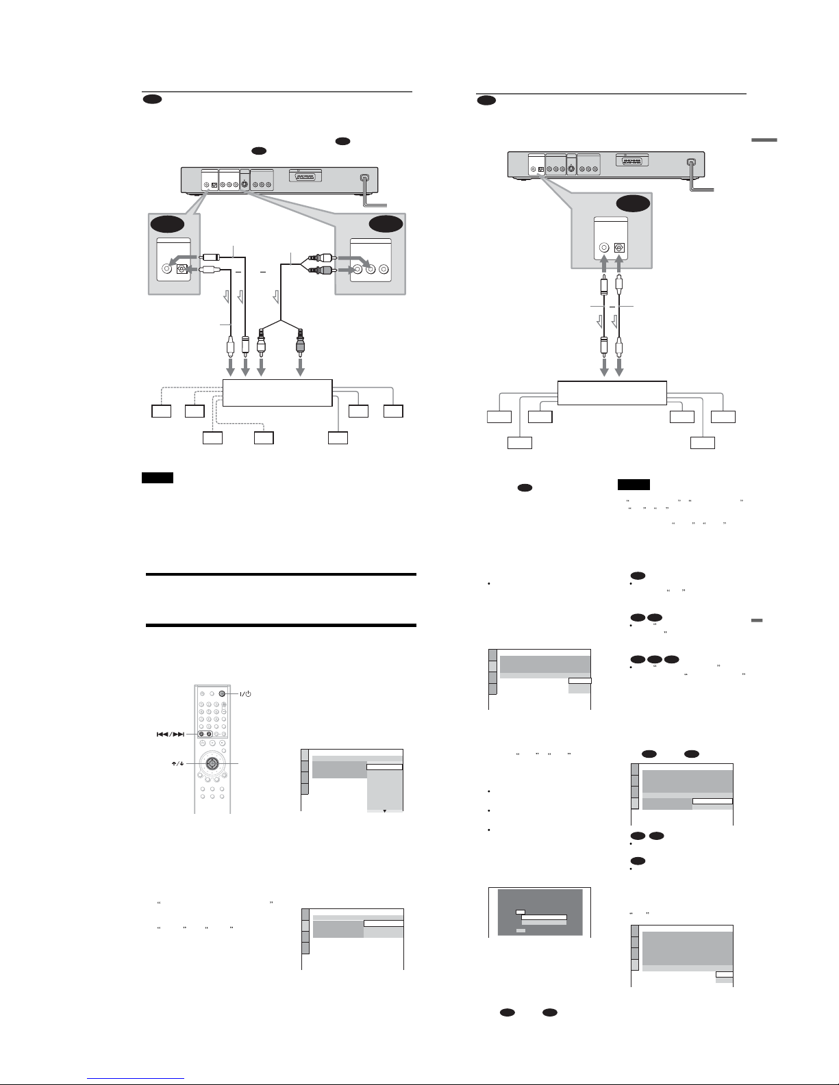
9
Front panel display
When playing back a DVD VIDEO/DVD-RW
When playing back a VIDEO CD with Playback Control (PBC) (32)
When playing back a CD, DATA CD (MP3 audio), or VIDEO CD (without PBC
Current title/chapter or playing
time (45)
Disc type
Current audio signal (48)
Lights up when you can change the angle (52)
Lights up during
Repeat Play (37)
Playing status
Disc type
Current scene or playingtime (45)
Playing status
Lights up during A-B Repeat Play (38)
Playing time (45)
Disc type
Current track (45)
Lights up during
Repeat Play (37)
Lights up when playing MP3 audio tracks (33)
Playing status
,
continued