manuals.online logo
Brands
  1. Home
  2. •
  3. Brands
  4. •
  5. Sony
  6. •
  7. Home Theater System
  8. •
  9. Sony SA-VA15 User manual

Sony SA-VA15 User manual

Other manuals for SA-VA15

1

Other Sony Home Theater System manuals

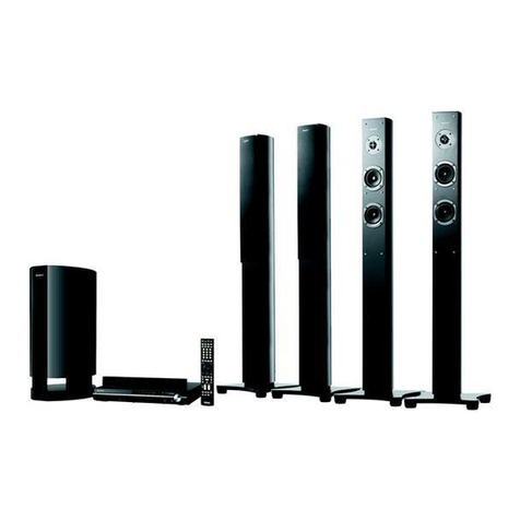
Sony HT-DDW890 User manual

Sony

Sony HT-DDW890 User manual

Sony Bravia Theater DAVHDZ273 User manual

Sony

Sony Bravia Theater DAVHDZ273 User manual

Sony DAV-TZ130 User manual

Sony

Sony DAV-TZ130 User manual

Sony Bravia BDV-E870 User manual

Sony

Sony Bravia BDV-E870 User manual

Sony DAV-FR10W - Dvd Dream System Owner's manual

Sony

Sony DAV-FR10W - Dvd Dream System Owner's manual

Sony HT-S700RF User guide

Sony

Sony HT-S700RF User guide

Sony HT-M77 User manual

Sony

Sony HT-M77 User manual

Sony HTSS1000P. Instruction manual

Sony

Sony HTSS1000P. Instruction manual

Sony HTD-710SF User manual

Sony

Sony HTD-710SF User manual

Sony DAV-DZ680W User manual

Sony

Sony DAV-DZ680W User manual

Sony BDV-F500 User manual

Sony

Sony BDV-F500 User manual

Sony BDV-N890W User manual

Sony

Sony BDV-N890W User manual

Sony BDV-IT1OOOES User manual

Sony

Sony BDV-IT1OOOES User manual

Sony HT-XT100 User manual

Sony

Sony HT-XT100 User manual

Sony HT-CT60 User manual

Sony

Sony HT-CT60 User manual

Sony HTR-6100 User manual

Sony

Sony HTR-6100 User manual

Sony BDV-NF720 User manual

Sony

Sony BDV-NF720 User manual

Sony DAV-HDX267W - 5 Disc Dvd/cd Player Home Theater... User manual

Sony

Sony DAV-HDX267W - 5 Disc Dvd/cd Player Home Theater... User manual

Sony RHT-G2000 - Home Theater Built-in Sound Rack... User manual

Sony

Sony RHT-G2000 - Home Theater Built-in Sound Rack... User manual

Sony BDV-E780W User manual

Sony

Sony BDV-E780W User manual

Sony HT-DDW760 Instruction manual

Sony

Sony HT-DDW760 Instruction manual

Sony DAV-DZ150K User manual

Sony

Sony DAV-DZ150K User manual

Sony DAV-DZ280 User manual

Sony

Sony DAV-DZ280 User manual

Sony BDV-T79 User manual

Sony

Sony BDV-T79 User manual

Popular Home Theater System manuals by other brands

Samsung HT-DL200 instruction manual

Samsung

Samsung HT-DL200 instruction manual

Samsung HT-ES6600 user manual

Samsung

Samsung HT-ES6600 user manual

Curtis DVD6010 instruction manual

Curtis

Curtis DVD6010 instruction manual

Philips MCD716/12 user manual

Philips

Philips MCD716/12 user manual

Sherwood ST-4108 operating instructions

Sherwood

Sherwood ST-4108 operating instructions

Philips HTS5520/12 quick start

Philips

Philips HTS5520/12 quick start

LG HT503PHW owner's manual

LG

LG HT503PHW owner's manual

Samsung HT-ES4200K user manual

Samsung

Samsung HT-ES4200K user manual

Samsung HT-P10 instruction manual

Samsung

Samsung HT-P10 instruction manual

Philips HTS5131 User manaul

Philips

Philips HTS5131 User manaul

Goodmans GDVD19SWS user manual

Goodmans

Goodmans GDVD19SWS user manual

Moxi media center user guide

Moxi

Moxi media center user guide

Samsung HT-EM35 user manual

Samsung

Samsung HT-EM35 user manual

Manta GK-500 user manual

Manta

Manta GK-500 user manual

Sharp SBW800 user manual

Sharp

Sharp SBW800 user manual

Philips HTS3541 user manual

Philips

Philips HTS3541 user manual

LG LHT799 specification

LG

LG LHT799 specification

Samsung HT-TWZ415 user manual

Samsung

Samsung HT-TWZ415 user manual

manuals.online logo
manuals.online logoBrands
  • About & Mission
  • Contact us
  • Privacy Policy
  • Terms and Conditions

Copyright 2025 Manuals.Online. All Rights Reserved.

SA-VATS
—
US
Model
*
REAR
SPEAKER
Canadian
Model
AEP
Model
UK
Model
E
Model
Australian
Mode!
Chinese
Model
*
FRONT
SPEAKER
SYSTEM
SPECIFICATIONS
Audio
Power
Specifications
For
front
full
range/center
woofer
speakers:
with
8
ohm
loads,
both
channels
driven,
from
70
Hz
-
20
kHz;
rated
20
watts
per
channel
minimum
RMS
power,
with
no
more
than
0.9%
total
harmonic
distortion
from
250
milliwatts
to
rated
output.
Amplifier
section
Continuous
RMS
power
output
Center
tweeter
Front
full
range/
Center
woofer
Super
woofer
Rear
Input
sensitivity/
impedance
Output
total
100
W
20
W
(8
ohms
at
10
kHz,10
%
THD)
20W
+
20W
(8
ohms
at
1
kHz,
10
%
THD)
20
W
(8
ohms
at
40
Hz,
10
%
THD)
10
W
+
10
W
(8
ohms
at
1
kHz,
10
%
THD)
450
mV,
50
kilohms
1/2:
450
mV,
1
kilohm
Center:
350
mV,
1
kilohm
Rear:
Accepts
only
supplied
rear
speakers
$S-SR151
R-ch:
Accepts
only
SA-
VA15
R-ch
speaker
with
supplied
exclusive
speaker
cord
Tone
control
Front/Center
Speaker
section
Type
Front
speaker
DBR
super
woofer
Rear
speaker
Speaker
unit
Front
speaker
system
Rear
speaker
General
Power
requirement
Power
consumption
Bass:
+10
dB
at
100
Hz
Treble:
+10
dB
at
10
kHz
Bassreflex
type
SAW
type
Bassreflex
type
Center
tweeter:
5
cm
cone
type
(x2)
Front
full
range/
Center
woofer:
10
cm
cone
type
(x2)
Super
woofer:
13
cm
cone
type
(x2)
8
cm
cone
type
(x2)
US,
Canadian
model
:
120V
AC,
60Hz
AEP,
UK,
German,
Malaysia,
Singapore,
Chinese,
Australian
model
:
220
—
230
V
AC,
50/60
Hz
US
model
:
110
W
Canadian
model
:
120
W
AEP,
UK,
German,
Malaysia,
Singapore,
Chinese,
Australian
model
:
80
W
—
Continued
on
next
page
—
HOME
THEATER
ACTIVE
SPEAKER
SYSTEM
SONY.
TABLE
OF
CONTENTS
Section
i
g
Dimensions
Approx.
180
x
1040
x
Ltle
Page
290
mm
(w/h/d)
7'/,x41x117/,
Me.
MOEA
iscatce
cat
nalenatdaoetctn
ton
sceadevsetasncas
eeimcoewmeetes
4
inches)
Approx.
250
x
1040
x
2.
DIAGRAMS
sabe
ee
:
2-1.
IC
Pin
Function
e
a
a
ie
ae)
-
IC501
System
Control
IC
(uPD78042AGF-065-3B9)
..
5
inenes)
:
2-2.
Circuit
Boards
Location
.......c.ccscesescessesssesessesseesestesesnsien
6
2-3.
Schematic
Diagram
—
Display
Section
—
.......c
ee
7
Mass
Front
(L):
16
kg
2-4.
Printed
Wiring
Board
—
Display
Section
—......
9
oe
2-5.
Schematic
Diagram
—
Main
Section
—
.....ccecccesseesees
12
(28
Ib
9
02)
6
2-6.
Printed
Wiring
Board
—
Main
Section
—
owe
17
Rear:
700
g/pc
(1
Ib
9
02)
3.
EXPLODED
VIEWS
3-1.
R
Speaker
System
Section
0.0...
ccc
ceceesesesecsssssseeses
21
Supplied
accessories
Rear
speakers
5S-SR151
3-2.
L
Speaker
System
Section
22
i.
FECLIOM
a
aassssssssssssseeeeeeeettttsnssssnssennes
Bron
b/eneake?
3-3.
Power
Suppley
Section......
saseeennonnasnansasecstsneeseeessanannannaens
23
connecting
cord,
3.5m
3-4.
Rear
Speaker
System
Section
(SS-SR151)
.......cceeee
24
(1)
Rear
speaker
4,
ELECTRICAL
PARTS
LIST
.00.........cceccccccecsesseeeeeeees
25
connecting
cord,
10
m
(2)
Audio
connecting
cord,
1.5
m
(1)
Remote
Commander
SERVICE
NOTE
RM-J15
(1)
eae
eae
[FL
all
light
up
mode]
While
pressing
the
|MASTER
VOL+]
button,
insert
the
power
plug
into
the
power
supply
inlet.
[AUTO
POWER
SAVE
MECHANISM]
A
part
of
circuit
on
this
unit
will
stop
to
economize
in
power
if
it
has
no
signal
after
more
than
three
minutes.
Flexible
Circuit
Board
Repairin
P g
If
a
sound
is
input
again,
the
normal
circuit
will
operate.
*
Keep
the
temperature
of
the
soldering
iron
around
270
°C
during
repairing.
¢
Do
not
touch
the
soldering
iron
on
the
same
conductor
ofthe
circuit
board
(within
3
times).
*
Be
careful
not
to
apply
force
on
the
conductor
when
soldering
or
unsoldering.
SAFETY-RELATED
COMPONENT
WARNING
!!
COMPONENTS
IDENTIFIED
BY
MARK
A\
OR
DOTTED
ATTENTION
AU
COMPOSANT
AYANT
RAPPORT
ALA
SECURITE!!
LES
COMPOSANTS
IDENTIFIES
PAR
UNE
MARQUE
A\
LINE
WITH
MARK
A\
ON
THE
SCHEMATIC
DIAGRAMS
AND
IN
THE
PARTS
LIST
ARE
CRITICAL
TO
SAFE
OPERATION.
REPLACE
THESE
COMPONENTS
WITH
SONY
PARTS
WHOSE
PART
NUMBERS
APPEAR
AS
SHOWN
IN
THIS
MANUAL
OR
IN
SUPPLEMENTS
PUBLISHED
BY
SONY.
SUR
LES
DIAGRAMMES
SCHEMATIQUES
ET
LA
LISTE
DES
PIECES
SONT
CRITIQUES
POUR
LA
SECURITE
DE
FONCTIONNEMENT.
NE
REMPLACER
CES
COMPOSANTS
QUE
PAR
DES
PIECES
SONY
DONT
LES
NUMEROS
SONT
DONNES
DANS
CE
MANUEL
OU
DANS
LES
SUPPLEMENTS
PUBLIES
PAR
SONY.
MODEL
IDENTIFICATION
—
BACK
PANEL
—
4-974-284-0001
:
US
Model
4-974-284-100
:
CND
Model
4-974-284-2001
:
AEP,
G
Model
4-974-284-30
:
UK
Model
*
For
detailed
SP,
MY,
CH
model
of
refer
to
AEP
model
*
For
detailed
AUS
model
of
refer
to
UK
model
Note:
*
Abbreviation
CND
:
Canadian
model.
G
:
German
model.
SP
__:
Singapore
model.
MY
=:
Malaysia
model.
AUS
:
Australian
model.
CH
:
Chinese
model.
SAFETY
CHECK-OUT
After
correcting
the
original
service
problem,
perform
the
following
safety
checks
before
releasing
the
set
to
the
customer:
Check
the
antenna
terminals,
metal
trim,
“metallized”
knobs,
screws,
and
all
other
exposed
metal
parts
for
AC
leakage.
Check
leakage
as
described
below.
LEAKAGE
The
AC
leakage
from
any
exposed
metal
part
to
earth
ground
and
from
all
exposed
metal
parts
to
any
exposed
metal
part
having
a
return
to
chassis,
must
not
exceed
0.5
mA
(500
microampers).
Leakage
current
can
be
measured
by
any
one
of
three
methods.
1.
A
commercial
leakage
tester,
such
as
the
Simpson
229
or
RCA
WT-540A.
Follow
the
manufacturers’
instructions
to
use
these
instruments.
2.
A
battery-operated
AC
milliammeter.
The
Data
Precision
245
digital
multimeter
is
suitable
for
this
job.
3.
Measuring
the
voltage
drop
across
a
resistor
by
means
of
a
VOM
or
battery-operated
AC
voltmeter.
The
“limit”
indication
is
0.75
V,
so
analog
meters
must
have
an
accurate
low-voltage
scale.
The
Simpson
250
and
Sanwa
SH-63Trd
are
examples
of
a
passive
VOM
that
is
suitable.
Nearly
all
battery
operated
digital
multimeters
that
have
a
2V
AC
range
are
suitable.
(See
Fig.
A)
To
Exposed
Metal
Parts
on
Set
AC
ra]
voltmeter
(0.75V)
=
Earth
Ground
Fig.
A.
Using
an
AC
voltmeter
to
check
AC
leakage.
Front
Panel
SECTION
1
GENERAL
[1]
Remote
sensor
AC
STANDBY
indicator
POWER
indicator
[4]
POWER
button
[5]
INPUT
button
[6]
SURROUND
button
CENTER
MODE
button
S.
WOOFER
button
[8]
MASTER
VOL
(+/-)
button
Display
window
This
section
is
extracted
from
instruction
manual.
Power
turns
on
and
off
automatically
The
speakers
turn
on
automatically
when
a
sound
signal
is
input
and
turn
off
when
you've
finished
watching
a
program
and
the
sound
signal
goes
out.
So
you
don't
have
to
bother
using
the
power
switch
every
time
you
use
the
system.
ot
.
Y
The
speakers
turn
on
and
off
automatically
(Auto
power
on/off
function)
Three
minutes
after
the
sound
signal
goes
out
(when
you
turn
off
the
TV,
or
the
currently
playing
video/
laserdisc
ends),
the
speakers
turn
off
automatically
and
the
POWER
indicator
turns
red.
The
speakers
turn
themselves
back
on
the
next
time
you
turn
on
the
TV
or
start
playback
from
the
VCR.
os
If
you
press
POWER
when
the
speakers
are
on
They
enter
standby
mode
and
the
auto
power
on/off
function
does
not
function.
You
have
to
press
POWER
again
to
turn
on
the
speakers.
SECTION
2
DIAGRAMS
2-1.
IC
PIN
FUNCTION
¢
1C501
System
Control
IC
(
uPD78042AGF-065-3B9)
[Pine
|
PinName
UO]
SSCS
SSSCSC~C~S~*
|
3s
[wo
[-
|
Power
supply
terminal
(+5V)
|
9
|
POWERRY
|
O-|
Power
relay
control
P10
[runcia
|
0
|
tnpuacectcneel
(cio?
Hip)
SSS
[|
riopenavek
|
0
|
|
12
|
PLOMELAY-CE
——|_
O_|
>
Dolby
IC
(IC
103,
104)
serial
control
pa
[rmonrr
«dt
|
is
|
CENTER
EXTMOT
|
0
[is
_[swmur
«dt
17
RESET
18
REAR
MUT
19
CENTER
MUT
20
AVSS
21
CENTER
EXT/INT
22,
23
24
Mute
control
(“L”=Mute)
System
reset
Mute
control
(“L”=Mute)
Dolby
IC
(1C103,
104)
serial
control
}
Key
input
(analog)
Analog
power
supply
for
A/D
convertor
Reference
voltage
for
A/D
convertor
Voltage
detect
Not
used
(open)
GND
VOL
SCL
NTN
ni
wm
n
_
Ww
KEY
1
KEY
0
AVDD
AVREF
STOP
T2
S
27
28
29
30
31
WwW
N
Ww
x
Vv.
Mn
Ww
a
x
i)
}
Oscillation
crystal
(S
MHz)
for
main
system
clock
36
S/W
BOOST
37
S/W
VOL-CE
38
S/W
VOL-DATA
39
S/W
VOL-CLK
SUB
WOOFER
boost
control
(H:
off
L:
on)
w
bp
_
S.
WOOFER
VOL
(IC403)
serial
control
Connecting
detection
of
external
center
output
40
aie
;
nd
,
(L:
Connecting
signal
input
H:
No
connecting
signal
input)
CENTER
EXT-SW
Pin
Name
CONT
SIRCS
-[5
INT
SIRCS
VOL
SDA-2
VOL
SDA-1
EXT
SIRCS
72
to
77
78
to
80
*
oo
—
e)
STANDBY
LED
OPRATE
LED
READY
LED
VDD
$24
to
$27
VLOAD
$6
to
S1
10G
to
8G
Remote
control
input
(outside)
Not
used
(Connected
to
GND)
Remote
control
signal
input
}
Electrical
volume
IC
(IC203,
204)
serial
control
Remote
control
input
(outside)
Internal
connecting
(Connected
to
GND)
LED
contro!
(L:
Lighting)
Power
supply
(+5V)
FL
segment
control
Power
supply
(-19V)
for
indication
control
FL
segment
control
FL
grid
control
2-2.
CIRCUIT
BOARDS
LOCATION
RSP
board
NOTE
:
aAand
aB
are
including
in
MAIN
board.
@A-
eF
are
including
in
POWER
board.
Abbreviation
CND
:
Canadian
model.
G
:
German
model.
PO-R
board
(e
E)
PO-L
board
(e
D)
PO-RE
board
(eC)
CONNECT
board
(eF)
WY
ren
EK
|
T2
board
(US,
AEP,
UK,
G)
T3
board
(CND)
PS
board
PO-CN
board
(eB)
PO-WO
board
(e
A)
MAIN-1
board
(4
A)
T1
board
DISP
board
MAIN-2
board
(4
B)
2-3.
SCHEMATIC.
DIAGRAM
—
DISPLAY
SECTION
—
NOTE
*
Ali
capacitors
are
in
BF
unless
otherwise
noted,
pF:
uur
SOW
or
less
are
not
indicated
except
for
electrolytics
and
fontaiums,
.
e
All
resistors
are
in
Q
and
|/4W
or
fess
unless
otherwise
Specified,
°
A
‘internal
component.
¢
[]
:panel
designation,
L50
FLUORESCENT
INDICATOR
TUBE
SOLDER
SIDE
VIEW
i
|
aotatetete
>
[B+]
:Bt
Line,
as
|
‘
j
Bo
Tt
°
(BP
Line,
a]
*
Voltages
and
waveforms
are
dc
with
respect
to
ground
under
no-Signa!
conditions,
no
mark:FL
oll
light
up
(See
Page
2)
*
Voltages
are
taken
with
a
VOM(Input
impedance
1(MQ).
513
R548
47k
Voltage
variations
may
be
noted
due
to
normal
produc-
Reg!
aad
leader
tion
tolerances,
S15
J
R546
47k
‘
‘
5
S161
wy,
R5KS
47K
'
*
Waveforms
are
taken
with
a
oscilloscope,
eee
Ha
Voltage
variations
may
be
noted
due
to
normal
produc-
A
k
Hee
$19)
RS42
47k
tion
tolerances,
S204
R541
47k
‘a
POWER
RY
ot
-
neat
C507
rae
mae
R540
47k
Raeseal
pens
oof
[a
rep
nm
Rane
|
PLO/BELAY-CE
|
0
:
PLO/BELAY-CE
10501
(2)
823-4
ROSB
47K
505
SMLI4760CN
Soe
aa
te
poveeiay-oata
-APO7BOSZAGF
065-389
-16.2-2),
7
824
RS37
47k
PLO/BELAY-CLK
|
0
ee
“<N@)
Proeetavcie
=
SYSTEM
CONTROL
7!*"?
R534
220
RED
¥
GRN
FRONT
MUT
|O
.
READY
LES
N
tots
CENTER
EXT
MUT
O
OPRATE
LED
|
cin
6.8
mee
erode
pts
oe
|
REAR
MUT
O
RESET
ne
=)
r
9504
SEL42148
CENTER
MUT
|
©
EXT
SIRCS
Ong
AC
STANDBY
CENTER
EXT/INT
©
ug
NOL
SSBAT!
er
10503
VOL
SBA~1
|
VOL
SBA-2
Om
As
GP
1U52xB
VOL
SBA-2
|
0
wees
Cay
r9
o)
I
AUTO-SW
Of
Sadak
+B
MAIN
BOARD
ew
Boost
10
R516
1k
rae
(3)
GNA
orto
S/W
VOL-CE
|
oO
+-——Fs!7
100
aman
c51
224
6.01
S/W
VOL-BATA
|O—4
Rolec1
0G
8G
6
1C503
S/W
VOL-CLK
}
of——f819
100
|
=
SIRCS
ee
BSE
_osap_
RECEIVER
a“
2802785
EXT
SIRCS
AS)
sat
-19V
4.9
1
PGND
I
VF
LL
VF
4}
et
©
TP!
|
©
1P2
—l
1502
|
uu!
[a
[vt
PSTbO0R
NANon
“Vo
2st2785
EH
|
OB
5
aT
i
8
I
RESeTsw
El
gl
fg}
fe
&
ot
=
1C502
7
gE
;
|
RESET
ra
Q9g
Ba
at
ee
os
a
tere
te
ene
a
Le
ee
A
ee
2-4.
PRINTED
WIRING
BOARD
—
DISPLAY
SECTION
—
(
MAIN
BOARD
CN
102
([DISP
BOARD]
CNI52
10
@EGEGoe
6a eE
ES
Cer
@——_}|__@)
C505
Jw506é
oto
<4
2eeceqegecgocoee¢e
eh
|
=
my
S
=
2
eh
06.
—
ip
FO
1p
in
Lb
Of
#501
o
pe
|
:
| :
ig
Wie
CO
Pk.
<
coer:
—
_
.
rem
R554
©.
we
oe
oe
aes
Intel
am
10
a
ca
Oe
es
ee
aig
—
TC
PPO
POQOVOD
P9ODODODODODOOOODOOOD
O
;
Yoox
=
%
—?
R552
r.
JW517
ola
64
R524
R525
eVW-e
6/4
ve
06
C)
=9502-
$504
S503
C)
——_—
C)
HH
|
fe]
ok
ee
i
¢
Semiconductor
Location
[et
o.[Locaton
Nh
ww
NN
a
@mo0
DOD
900
N
—
©
A@®+§
Note:
SA-VA15
*
o—
—
:
parts
extracted
from
the
component
side.
*
A:
internal
component.
“=:
Pattern
from
the
side
which
enable
seeing.
SA-VA15
2-5.
SCHEMATIC
DIAGRAM
—
MAIN
SECTION
—
Jidl
=
—=——————_—
SS
—
OT
TS
Oo
nr
ea
CT
OO
8
En...
4P
-
-
PRO-LOGIC
|
jy
(MAIN-1,
MAIN-2
BOARD]
10s
]
A
[
[1]
:
as
He
C106
0.022
4.7
cae
a
?
zd
=
+
iy
RB
ve
ae
IN
RISI
: ,
“9
CLK
ag
4.7
SOV
100
I
R
@
Ne
1€101
©
cux
()
>
=s
c=
(iam
O30)
BAIFAN
MUTE
302
25C3623A
MUTE
a
~
He
Ms
IC101
MCt4052
INPUT
SELECTOR
C107
0.047
4.6 4.9
aS
|
C20
FVOL.
BASS.
TRE
10203
TBA7315
elie
ol
BATA
{$$
ia
C205
om
ee
@
7
C108
220
10¥4.5
os
a5
10104
5
baad
L
5
4.8
Ss
Diz
2
+
CE
oO
z
Q305
put)
RIZ3,
47K
;
©
Ba,
BELAY
ay
1€202
33
oe
Og
255i
Re5
5P604
SP605
SP&0é6
C109
10
50V
4.8
0
C138
6800
=
TER
R
WOOFER
R
LL
R
Ca
+
C)
ee
ae
1C104
LYI011
1C201
IN/EXT
SW
|
|x
aie
8
0
9.2
()
FRONT
R
CENTE!
C110
10
50V.
4.5
g.1
C137
10
5!
0.7
4.2Vp-p
8MH
=
~t
=i
so
sPpé0i
SP602
SP4603
5
ms
ae
:
Q
pop
BMHZ
L4CENTER
R+CENTER
1¢202
Mc14052
nae
ee:
of
2
2
I
—
~
Peo}
SP602
|
SPAOS
,
B
ee
et
Valg
208
“3
@e
CLK
AIS
Ie
ie
2a
=)
|e
zz
ao
sri
gs.
Bat
Sx
os
wi
@
onM/
\1é
CHW
\I6
OH
R
CH
Hee
zl
LOUT
=e
ON
on
mt
=
[oa
>
>
a
ae
Or
C112
10
Sov
2
es
pat
Rid
ix
|
4:8
eee
1548,
R403
RADE
|e
|
ng
;
a a
[CONNECT
BOARD]
=
4
ne
<
a>
*
a
z
a
<
ae
ean
Gancen
ecaieR
4P
|
|
[RSP
BOARD)
ROUT
>
AW
g°
aeS7
FETT
TAG
8
CN602
c
OUTPUT
Ao
C13
uae
Qe
ce
RIS
Ik
4.9
(B-]
=
1C402
g
02 of
C1)
_—___
-
PO-R
BOARD]
—_—_—_——
-
as
4P
vid
Bay
—
i
coal
-—
——<———
|
LINE=2
-
©
C114
3.3 SOV
&
,
d
C136
10
SOV
CT
cise
2.2
SOV]
2.9
~
10301
[a]
|
4
ee
:
Ll
—_—=
rps.
BOARD]
“ee
0
=
LIN
+
———
XN
:
a
l
I
Clis
8.
:
;
z
ES
cans
:
hs
om
15
il
&
si
&
a
47
50V
Rig
33k
|
8
a
3
ot
te Se
1c602
(C602
5118751
[B+)}
oat
jf
tt
r
yo
¢
59
9
CNS
Cc
Cal
=
5
®
ae
‘aad
EUAS
2205
10N
82
ar
5
£9
css)
ee
,
F.RCH308B
Ca
RY7O1
Tt
I
FRONT
WOOFER
CENTER
|
(9-7
-GpEAKER
ee
4,
7
S
SF
rT
(1)
INPUT
192
|
$s
35
aad
(4)
:
r
{_t
R
CH
ap
=
t—-®)
©)
2
__
\
2s
+t
Bp
C116
0.1
C133
0.1
4.5
CNIS3
82]
0
@
i
—_t—}
-
}
a
C17
0.1
= ©
C132
0.1
RII7
15k
4.5,
BS
Poe
=|
_
I
:
2
ie
24-7
E-]
33
oe
(T2
BOARD]|
A
I
rT
AM
—
R407.
33k
6
3
=
i
AT
C118
0.47
SOV
C131
0.47
SOV
=!
fz
~
2seae33A
CN}03
|
Front
ace
|
3
=
tt
i
]Sa
1C901
+988
re
CNS54]
cNg04
TRANBCORMER
T1
F—&)
@)—=
S|
[8
mY
MUTE
P
|
BRL
G99
7°67
Dey
alo.
AB
83
fy
NZ
ie
POWER
oP
oP
D
I
SIGNAL
SENSER
C119
4.7,
50V
& >
hae
5ov
REAR
Si
#2
2
Cy)
Pee
eetee
hi
in
=
\
ayy”
SOV
|
cngps
cngss
|
|
ROE
330
+9V
REG
B
|
int
RS
RYSOI
BOARD
1c102
M5218
C120
0.47
SOV
C129 0.47
SOV
=) |e
z
pare
0
Been
=
=
col
a:
F257
a
leer
)
@)—
CENTER
1C401
=
7
Ro
Ba
ae
FRONT
RCH
Tl
eaoree
|
ttf]
ey
:
tee
G5)
—_
OMOQ?
:
“ail,
7
© &
ae
SOV
L+R+CENTER
3
su
>
I]
[PO-L
BOARD]
|
Fe
ov
[B+]
5
ad
CN1O1
0
0
:
SW
c122
0.15 C127 0.15
314.
R321
o4
REAR
——_—_—_—
-
we
9913
11ES2
R301
ap
4
os
t
3
4.7
Sov
160
0
1c601
$118751
a
Biv.
id
aa
P08
N41
48M
.
128
3.3
SOV
i =
C126
3.3
SOY
Q
EE
a
|
eeENTER
1C601
a
-f
LCH
ene
Ty
ic901
7aMo9
RID.
15k
col
Ril!
haat
QS
°
oH
REAR
Kame
ETAL
IN
aye
[00K
f
i9
B
C124
0.15
c128
0.15
xy
a
Foy
oni
aaa
oh
cestete
oi}
|
ET
Bal
ha
PL
13.9
[BF]
alae
ae
even
|_|
oa
-
ag
Law
t
=
®)
®)
ba
1C204)
cei
01
I
we
ll
ercoreR
i
.
ht]
=)
ts
F
an
ra
eg
i
E
me
Se
ze
TER
35
EE
REAR.
CENTER
VOL
C260
0.1
:
38
Ci
esl
Spisit
y
Be
i)
ab
sk
a3
2A
PEC
=
3
2
=
it~
;
2
CST
6.4
BAP
RET
470
Se
“8
“|
9903
11692
z7P
:
11C403]
*
mele.
=
r
8
3
SEF)
Ae
[|
1C701
Spal
ge
|
osm
tesa
POWER
RY
B+]
%
1C302
is
sw
VOL
fay
PROTECT
aah
SN
ov.
eat
te
Ae
rl
A?
FUNC
1/2
.
=
~x
=
8]
By
Baye
re
.
INT-C_HPF
oh
=5.
6vl
[B-
PLO/BELAY~CE
oe
Ntsc
“AMP
a=
I
By
apy
nt
Canoe
Ve
L
5
I
#PCT237HA
14.7
9905
11e52
I
PLO/BELAY-BATA
[isle
wes
reele
(B-]
=3V
F_
1902
73409
9908
1
1E52
A
PLO/SELAY~CLK
8
R316
Dx
fg
+I
F
FRONT
MUT
|
FR
MUT
"
EST
z
914
RSI
CENTER
EXT MUT
|
©
I
L}
DEIR
CONTR
an
Bes
oe
LEN
2.
ot
B)
Arey
10
Spas
=
o%
Loy
lotr
.
“OV
REG
SSF
ST
PRT
BT
nS
=
Me
7
2841175
1
a
a
a
TR
j
wy
2
|
48
ie
oe
a
ee
Be)
"EHE
|p
7
REAR
MUT
o
Pt
Te
Mur.)
s
I
|
are
A
33k
|6.
8k
20
126
ese
ao
|
3%
<
Bi
A
WMTW)
es
ee
ee
a
ee
CENTER
MUT
|
CE
MUT
ut
BS
Fae
ane
[a
NM
Bs
US,
AEP,
UK,
G
MODEL
w
=
eS
7
f
-0.8
CENTER
EXT/INT
O
ae
ae
@201~205
2
3s
=]
“a
=
a
fB-]
=13V
;
24.8
[B=]
vol
saA-1
|o
wit
ion
DA
MUTE
SW
=
|
a-mcse
So
|
BS
NLAeH
ag02
2581640
-19V
REG
<
VOL
SCL
|o
A
3
3
1
=
2
.
auTo-sw
|
i.
I
aisp
3
Boost
[oH
g|
358
wil
0702
FOO
ia
sn
em
eee
ae
aa
;
ear
BOARD
S/W
VOL-CE
|}
oO
\
wed
4.7/50V
(US,
CND
MODEL)
5
ik
10/50V
(AEP,
UK,
G
MODEL)
1000/25V
(AEP.
UK,
G
MODEL)
CN152
S/W
VOL-DATA
|O
DATA
i
I
2.
nos
—
pr
nnn
at
a
POWER
s/w
voL-cLK
|
oO
ne
=
TRANSFORMER
CENTER
EXT-SW
|
©
eee
i
cont
sincs
|
oft}
H
EXT
SIRCS
[B+]
BOOST
32HZ
|
ASé0t
cpr
ssxz
[1
C405
|
apr
conz
~19V
oO
B=)
£40.
1C404
R423
1.2K
[p-
9.2
0.
$2!
Pov
sos
dseoe
p33
l
|
C1
04
LV1
01
1
5.6V
ser
I
i
.
FHF
5
Le
ae
R458
12k
8
C414
R441
C416
GLB
ae
|
fiGND
Oo
F
chog
cao”
4
ee
eS
1
1,0
+
7{
10
50V
tk
=
4.7
50V.
100
x
|
ea
=
“ov
|
Sov
“a
10K
a
|
G42
cata
|
6
Le
a
We
—
9d
€£$"
I
8g
3
vss
(1)
i
7
ee
ee
ee
3
ue
WH
Te
:
3
aux
(Tg
<<
a3
a
ay
8s
BOCST
‘SV
ra
=
alien
9.2
of
yee eee
3
3
|
ay
ae
E
d
|
|
a
a
a
ee
=
aes
a
iy
7
0
cai7
$48
|
0k
‘~
25056234
|
ra
ENABLE
5
7
=
L\
F903
-
MUTE
-
LATCH/
I
I
nab
of
C4)
ane
xx
Les
z
23
Sx SS
vB
S
Pi
&
=
@3)
AUTORESET
5.
1SA125V
1C103
LA2785
eet
ee
1C203,204
TDA7315
oF
ee
TEs
a7
185
= =
cept
Ge
g
3
8
ah
og
ae
Q16
OUT OUT
BOUT
BIN
BOUT
BIN
aaa
=
—s—<+—
I
©
eee
>
=!
fog
n
u
TM601
p++
SCL
SBA GND
~—sLEFT.-
«=
RIGHT~—s
a)
)
io)
)
L
4P
——
— —
———"°\_p
$8)
6)—9)
G5)-—B4)
_
vec
(7)
6)
I
A.
—
-
——_
-—__[©_©
0
©|
—epeerepey
ee
=
>
-
+
—
-
ss-8
ss
/\,
/\
Bx AS
Lat
Lp
12PN
7
S
L-IN
@)
|
9
3
J
—
REA
SPEAKER]—
i
i
ate
es
v
a
“Te
|
S87
Ron
@)
45
=
a
g
+
Se
l
y-
fs
NOTE
g|
sl
2¢
L,
Bl
Sis
Fa
5
: : :
——
:
:
x
om}
C6205
6424
S-IN
(0)
2
)
*
All
capacitors
are
in
fF
unless
otherwise
noted.
pF:
pur
Note:
Note:
*
Voltages
and
waveforms
ore
dc
with
respect
fo
ground
¢
Signal
a
l
3
Fs
7
ek
(7)
aena
6
?
er
}
ar
3%
-signa!
conditions,
=>
‘
]
arn
Se
SOW
or
less
are
not
indicated
except
for
electralytics
|The
components
identi-|
Les
composants
identitiés
par
UNa
ee
saps
ONG
et
eae
ees
eee
ed
ae
K
©
ond
fontalums,
fied
by
mark
ANor
dot-|
une
marque
AX
sont
critiques
no
nrk:FL
ol!
light
up
Gee
Page
2)
ed
“FRONT
~
7
ae
#
is
ESN,
+All
resistors
are
in
Gand
1/4W
or
less
unless
otherwise
|
+04
jine
with
Nite
AS
niner-fo-seourtth
*Voltages
are
taken
with
a
VOM([nput
impedance
|0MQ).
>
PEAR
(9
L-wix-ouT
5
ifi
ne
;
iati
be
noted
due
to
normal
produc~
°
specified,
are
critical
for
safety,|Ne
les
remplacer
que
par
une
ee
my
p
>
WOOFER
aia
7"
ee
STB
EM
RonpanenT,
Repiace
only
with
part
|
piéce
portant
le
numro
spéci-
ie
Rc
eaeccaa
.
>:
@
Crue
=
°
iW
cnonflammable
resistor,
number
specified
fid
*\Woveforms
are
token
with
a
oscilloscope,
Me
ea
oO
—
.
’
.
ae
L
=
.
spanel
designation,
a
Voltoge
variations
moy
be
noted
due
to
norma!
produc-
ue
.
ae
iing
¢For
detailed
SP,
MY,CH
model
of
refer
to
AEP
model.
tion
tolerances,
a
model
of
refer
to
model,
oo)
:
BV
be:
For
detailed
AUS
UK
IN(R)
VS
AGNS
TREBLE TREBLE
R
Lqud
«N.C
LOUDON
ae
i
eS
a
‘o
*
Abbreviation
CNB:Concdian
model,
MY
:Malaysia
model,
O©@
G:German
model.
AUS:
Australian
mode!
09
;
SP
:Singapore
model.
CH
:Chinese
model,
ee
ell
a
|
—15—
ca
SA-VA15
2-6.
PRINTED
WIRING
BOARD
— MAIN
SECTION
—
*
See
page
6
for
Circuit
Boards
Location.
[oS
eee
a
es
G8
a
Oe
ee
ie
eK
ee
i8
I9
|
20
Allon
=
Oe
3
oe
ah
a
ee
el
oe
i
ee
|
a6
|
«
Semiconductor
Location
etn,
[Locaton]|
Rene
[Loceton|
C-3
:
CONTROL
S$
[REAR
SPEAKER]
[PS
BOARD)
36
A.
{MAIN-1
BOARD]
[MAIN-2
BOARD]
(A
§|
,
CRSP
BOARD]
(PO-RE
BOARD]
(PO-L
BOARD}
(PO-R
BOARD}
a7
|
aii
os
Oana
2
oe
Poem
=
ae
s
)
0.
6.
6,6
©
Se
ee
sj
oe
oo.
a
@ :
<
Wid)
Ye
ita
eS
eae
—
]
oe
D
Buate.
.
aes
cles
1@
0
© ©
OO
Os
Ee
=
.
Se
Re
Beppe
9
1@
©
0
6
6
6
OB.
i
C-9
=
ae
.
IWi7s
: :
’
&
©
: i
:
a
: :
i
=e
2
ae
|
—
E-14
a
@
@)
Si
‘4 ‘f
a
fs
B
i
ee
€
ee
.
E-15
C
eS
(@
Oe
JW10S
a
:
dwt
45
:
fis
92)
:
i
ae
anes
a
*
;
i
W146
£
:
7
:
See
2
ST)
eh
‘6
eet
N@
eye
ee
:
wisi
*
fe
CR
ou]
|
-
J-17
e ©
31s
SV
Ts
:
ae
:
RY70
|
pee
es
7
neu
apal
wy
8425
cee
656
-787-
[Uh
H-17
z
ee
s
ee
me
4.
A
-17
oe
A
I-15
C
A
I-15
I-7
ie
las
[eonane
Fou)
Sool
Saad
b
Zq
=
E
of
Sool
Su
F
be
©
f/z/=lEl=/=
cele
Siecle
7A
G-16
1-8
8
@
G8
Boe
Go
eo
on
a
Rea
Tiger
Cryer
oO
a
feces
Sis
OF
Be
eh
OF
he
Nh,
O~
.
a
SP604
5P605
SP606
Oe
On
OS
Oo,
os
=
a
Oe
a
ON
PRP
o
HO
GON
ele
Ses
ae
Ae
ne
oeeee
Bg
ed
a
og
G-15
1-8
i
FRONT
CENTER
WOOFER
.
a
:
“
G-17
1-9
oo
Roh
SPEAKER
1-9
©
°
1-5
D-8
D
D-7
D-9
E-9
Lch
SPEAKER
F-6
5P6O!
SP602
—-SP603
F-8
FRONT
CENTER
WOOFER
F-6
D-8
E
D-7
I-15
ess
aly
ales
|-656-
788
~
ken
F-15
H-17
L
be
—
Note:
US,
AEP,
UK
,G_
MODEL
CNOMODEL
*
o——
:
parts
extracted
from
the
component
side.
|__|
:
a
.
"
-
A:
internal
component.
|
|
oo
+
Pattern
from
the
side
which
enable
seeing.
(Tl!
BOARD]
|
|
;
Powe
|
|
*
Abbreviation
TRANSFORMER
|
!
|
CND
:
Canadian
model.
G
)
|
|
:
G
_—_:
German
model.
oo
|
cN904
SP
_
:
Singapore
model.
NM
FC
|
|
bo
|
MY:
Malaysia
model.
Nia
|
|
a
:
°
!
AUS
:
Australian
model.
Jeo
tla
|e
|
.
|
.
CH_:
Chinese
model.
e
oso
Slo.
ka
ob
°
|
|
‘a
|
*
For
detailed
SP,
MY,
CH
model
H
4
oh
tle)
ies
Eg
O
6
=
°
|
3
|
|
°
of
refer
to
AEP
model
d
ot
ce
|
:
mo
,
io
a.
oe
io
:
ot
|
7
5
e
|
oF
|
o
|
°
+
For
detailed
AUS
model
of
refer
ie
a
wp
fero
|
i‘
al
Eee
a
o
|
:
|
9
to
UK
model
“@e
°
|
°
°
sh
ie
1°
|
7
|
2
|_|
nO
al
ees
o
o
&
Tee
me
|
Esa
208:
ok
aoe
ee
#
Ss
oe
Dp
|
|
08
|
és
'
i?
v
S
Rar
oO}
st
28
te
cm
| |
|
oie
8.
eS
:
C
le
octal
ope
Oe
Tweed
Boe
ie
#.
JW250
oe
ge
CNS84
,
.
.
ewe
ewe
ae
Be
Se
Gc
eze
Gc
eae
ioe
a
e
eS
|
|
l
R202
cnese
Bape
JWi70
ce
ol
ZF
O8
OB
OBS
©
a
a
S
xy
=
{
|
:
404
f
fos
oP
Cr
Sac
2
ise
dec
Ls
0203
Q204
eee
s
us
re
-
:
o)
a
:
oa
ake
|
&
2
Sx
W171
-
Top...”
pes
A125
5
:
se
Shae
6
:
eo
8
.
dwize
|
:
BS
N
ru
ENIOZ
Sect
ee
bey.
be
eg
tees
ey
ba
|
Q
cS
ot
hed
:
7
ry
:
=
q :
ee
BS
Re
|
|
See
S
20
OO
6
OG
8
6
6
6
6
6
os”
oe
oe,
®
c
|
?
:
x
©
ee
ae
On
,
ele
|
|
~~
|
.
.
}.}.}.}§}§&3§3§3§3§=»§=§—
My
ee
Soe
|
Saas
4
7
|
ee
~)
=
aa
:
O
[ri]
of
i-
656-794-f
|(1
|)
|
|
«
:
Ls
oo
S
:
ae
|-656-783-
tT
1-656
-784-
KL!)
C)
oO
©)
|
|-
656-795
-
|
|
1-657-171-
FF
Ul)
09
: : : : :
©
{CHASSIS}
o
mites
2,
Se
eee
oe
net
ees
et
Be
ee
4
a
eee
ae
ae
ts
TUR
aan
a
NUE
Pi
7
ys
ge
|__]
wi
J
kG
ee
aos
=
18
eet
|
Qi
Pe
Ue
SECTION
3
EXPLODED
VIEWS
NOTE:
*
Items
marked
“
*
”
are
not
stocked
since
they
are
seldom
required
for
routine
service.
Some
delay
should
be
anticipated
when
ordering
these
items.
CND
*
The
mechanical
parts
with
no
reference
number
AUS
in
the
exploded
views
are
not
supplied.
SP
*
Hardware
(#
mark)
list
and
accessories
and
Na
packing
materials
are
given
in
the
last
of
this
parts
list.
model
e
Abbreviation
:
Canadian
model
:
German
model
:
Australian
model
:
Singapore
model
:
Malaysia
model
:
Chinese
model
¢
For
detailed
SP,
MY,
CH
model
of
refer
to
AEP
The
components
identified
by
mark
A\
or
dotted
line
with
mark
A\
are
critical
for
safety.
Replace
only
with
part
number
specified.
Les
composants
identifiés
par
une
marque
\
sont
critiques
pour
la
sécurité.
Ne
les
remplacer
que
par
une
piéce
portant
le
numéro
spécifié.
¢
For
detailed
AUS
model
of
refer
to
UK
model
3-1.
R
SPEAKER
SYSTEM
SECTION
Ref.No.
Part
No.
Description
Remark
|
Ref.
No.
1
X-4945-944-1
FRAME
(R)
ASSY,
GRILLE
*
10
x
2
4-973-506-01
PANEL,
FRONT
*
il
3
4-914-518-11
SCREW
(4X14),
(+)
(B)
TAPPING
*
ll
x
4
4~975-254-01
FRAME
(R),
TWEETER
12
#5
A-4361-507-A
CABINET
(R)
ASSY,
SPEAKER(US,
CND, AEP,
UK)
13
"5
A-4361-742-A
CABINET
(R)
ASSY,
SPEAKER(G)
14
*
6
1-656-787-11
RSP
BOARD
15
*
7
4-974-287-01
PANEL
(R),
BACK
SP604
8
4-907-233-11
SCREW
(4X25),
TAPPING
SP605
*
9
4-973-511-01
COVER
(W)
SP606
Part
No.
Remark
Description
4-973-512-01
DUCT
(LS)
4-973-514-01
DUCT
(T)
(US,
CND,
AEP,
UK)
4-974-281-01
DUCT
(T)(G)
1-775-760-11
CORD,
CONNECTION
1-769-815-11
CORD,
CONNECTION
4~-$73-509-01
BASE
4-976-546-01
BASE
SCREW
(4X18)
1-504-874-11
SPEAKER
(5CM)
(FRONT)
1-504-875-11
SPEAKER
(10CM)
(CENTER)
1-504-876-11
SPEAKER
(13CM)
(WOOFER)