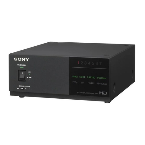
Sony BDX-M1000 User manual

MPEG MULTIPLEXER UNIT
BDX-M1000
INSTALLATION MANUAL
1st Edition (Revised 1)
Serial No. 10001 and Higher: BDX-M1000

BDX-M1000
!WARNING
This manual is intended for qualified service personnel only.
To reduce the risk of electric shock, fire or injury, do not perform any servicing other than that
contained in the operating instructions unless you are qualified to do so. Refer all servicing to
qualified service personnel.
!WARNUNG
Die Anleitung ist nur für qualifiziertes Fachpersonal bestimmt.
Alle Wartungsarbeiten dürfen nur von qualifiziertem Fachpersonal ausgeführt werden. Um die
Gefahr eines elektrischen Schlages, Feuergefahr und Verletzungen zu vermeiden, sind bei
Wartungsarbeiten strikt die Angaben in der Anleitung zu befolgen. Andere als die angegeben
Wartungsarbeiten dürfen nur von Personen ausgeführt werden, die eine spezielle Befähigung
dazu besitzen.
!AVERTISSEMENT
Ce manual est destiné uniquement aux personnes compétentes en charge de l’entretien. Afin
de réduire les risques de décharge électrique, d’incendie ou de blessure n’effectuer que les
réparations indiquées dans le mode d’emploi à moins d’être qualifié pour en effectuer d’autres.
Pour toute réparation faire appel à une personne compétente uniquement.
For the U.S.A.
Attention-when the product is installed in Rack:
(For BDX-M1000)
1. Prevention against overloading of branch circuit
When this product is installed in a rack and is
supplied power from an outlet on the rack, please
make sure that the rack does not overload the supply
circuit.
2. Providing protective earth
When this product is installed in a rack and is
supplied power from an outlet on the rack, please
confirm that the outlet is provided with a suitable
protective earth connection.
3. Internal air ambient temperature of the rack
When this product is installed in a rack, please make
sure that the internal air ambient temperature of the
rack is within the specified limit of this product.
4. Prevention against achieving hazardous
condition due to uneven mechanical loading
When this product is installed in a rack, please make
sure that the rack does not achieve hazardous
condition due to uneven mechanical loading.

1 (E)
BDX-M1000
Table of Contents
Manual Structure
Purpose of this manual .............................................................................................. 3
Related manuals......................................................................................................... 3
Contents ..................................................................................................................... 3
Trademark.................................................................................................................. 3
1. Installation
1-1. Installation Environment .............................................................................1-1
1-2. Power Supply ..............................................................................................1-1
1-2-1. Power Specifications ..................................................................1-1
1-2-2. Power Cord.................................................................................1-1
1-3. External Dimensions ...................................................................................1-2
1-4. Rack Mounting............................................................................................1-2
1-5. Matching Connectors and Cables................................................................1-5
1-6. Input and Output Signal of Connector ........................................................1-6
1-7. Switch Setting of Connector Panel .............................................................1-7
1-8. Settings of Internal Switches.......................................................................1-8
1-8-1. IPM-81 Board.............................................................................1-8
1-8-2. OPM-25 Board ...........................................................................1-9
1-8-3. SY-244 Board...........................................................................1-11
2. Service Overview
2-1. Cleaning of Air Filter ..................................................................................2-1
2-2. Description of Internal Indicators ...............................................................2-2
2-2-1. IPM-81 Board.............................................................................2-2
2-2-2. OPM-25 Board ...........................................................................2-3
2-2-3. SY-244 Board.............................................................................2-4
Appendix. Setting of Output Data Rate


3 (E)
BDX-M1000
Purpose of this manual This manual is the installation manual of the BDX-M1000 MPEG Multiplexer Unit .
This manual is intended for use by trained system and service engineers, and
describes information regarding installation.
Related manuals Besides this installation manual, the following manuals are available for the BDX-
M1000.
..
..
.Operation Manual (Supplied with the BDX-M1000)
This manual explains the overview of the BDX-M1000, and the system configura-
tion examples.
..
..
.Maintenance Manual (Not supplied with the BDX-M1000)
This manual describes information that premise the service based on board
replacement and parts replacement (adjustments, board layouts, schematic dia-
grams, parts list, etc.).
If this manual is required, contact your local Sony Sales Office/Service Center.
Contents The following is a summary of all the sections for understanding the contents of this
manual.
Section 1 Installation
Explains the operating environment, the connector information for peripheral
equipment connections and how to rack mounting, etc.
Section 2 Service Overview
Explains the periodical replacement parts and internal indicators.
Trademark
.Ethernet is a registered trademark of Xerox Corporation.
Manual Structure


1-1 (E)
BDX-M1000
Section 1
Installation
1-1. Installation Environment
Operating temperature : 5dC to 40dC
Storage temperature : _20dC to +60dC
Operating humidity : 20%to 90%(non-condensing)
Do not install the BDX-M1000 in the following locations:
.Areas where the unit will be exposed to direct sun light
or any other strong lights.
.Areas near heat sources.
.Dusty areas or areas where it is subject to vibration.
.Areas with strong electric or magnetic fields.
.Areas where is subjected to electricity noise.
.Areas where is subjected to static electricity noise.
To prevent the temperature rise inside the BDX-M1000,
pay careful attention to circulation of air in the place where
the BDX-M1000 is installed.
The rear side of the BDX-M1000 should be at least 20 cm
(8 inches) away from walls for ventilation and
maintenance.
c
Do not block the ventilation holes.
If the ventilation holes are blocked, overheating inside the
unit may cause fire.
1-2. Power Supply
1-2-1. Power Specifications
Power requirements : AC 100 to 240 V
50/60 Hz
Current consumption: maximum 2.0 A (at 100 V)
maximum 1.0 A (at 240 V)
A switching regulator is used for the power supply of the
BDX-M1000. The voltage within the range of 100 V to
240 V can be used without changing the supply voltage.
n
As the inrush current at turn-on is maximum 20 A (at
100 V)/maximum 40 A (at 240 V), the capacity of the AC
power must be adequate with the inrush current of maxi-
mum 20 A (at 100 V)/maximum 40 A (at 240 V).
If the capacity of the AC power is not the adequately large,
the breaker of the AC power at the supply side will operate
or the BDX-M1000 will abnormal operate.
1-2-2. Power Cord
w
To avoid a fire or an electric shock, be sure to use the
designated power cord. And do not damage to the power
cord.
n
For the customer outside of the area as shown above or in a
part of Europe, the above-mentioned power cords can not
be used.
Use the power cord that is applicable to the places in the
world.
1 2
2
2
Power cord for the customer in the U.S.A. and Canada.
1Power cord set !1-557-377-11
2Plug holder (Black) 2-990-242-01
Power cord for the customer in the United Kingdom.
1DK-2401 (UK) (approx. 2.4 m)
2Plug holder (Black) 2-990-242-01
Plug holder is included in DK-2401 (UK).
Power cord for the customer in Europe except the
United Kingdom.
1DK-2401 (AE) (approx. 2.4 m)
2Plug holder (Brown) 3-613-640-01
Plug holder is included in DK-2401 (AE).
AC inlet
AC inlet
1
AC inlet
1

1-2 (E) BDX-M1000
1-3. External Dimensions
(Front view) (Right side view)
(Top view)
Front panel
Unit : mm
Mass : 17 kg
894
892 475
424
450
304.883.7
66
57.2
132.4 (3U)14.5
44
254
101.6
482
465
424
482
1-3. External Dimensions
1-4. Rack Mounting
The BDX-M1000 can be mounted in a 19-inch standard rack.
n
.When the BDX-M1000 or the peripheral equipment is mounted in a 19-inch standard rack, it is recom-
mended to install a ventilation fan to prevent a temperature rise in the rack.
Make sure that all the units in the rack should be operated within the temperature range of 5dC to 40dC .
.Connect the enough long cables on the rear panel, considering that the BDX-M1000 is pulled out.
.An installation manual is supplied with the RMM-30 rack mount rail. However follow the instructions
in this manual. Because the rack mounting procedures of the BDX-M1000 are different from the
procedures explained in RMM-30 installation manual.
.To prevent falling the rack, fix the rack on the horizontal firm floor with bolts.

1-3 (E)
BDX-M1000
1-4. Rack Mounting
Rear bracket
Front bracket
Outer rail
Required parts
.Rack Mount Rail, RMM-30
Rail with bracket : 2 pcs.
Screw (B5x8) : 8 pcs.
.Screw for inner rail (B4x8) (*1) : 6 pcs.
.Screw for rack mounting (RK5x16) : 4 pcs.
(Sony part number: 7-682-378-04)
.Washer for rack mounting : 4 pcs.
(Sony part number: 2-297-913-01)
(*1) : The BDX-M1000 comes with the eight screws. The
two screws of them are spare.
n
Be sure to use the RMM-30 Rack Mount Rail.
If a rack mount rail other than the RMM-30 is used, the
BDX-M1000 may be dropped by insufficient strength of
the rack mount rail. This may cause a injury.
Procedures
1. Turn the power off.
2. Remove the four feet from the bottom of the BDX-
M1000.
3. While pressing the stopper of the rail, pull out the
inner rail.
4. Attach the inner rails to the BDX-M1000 using the six
screws (B4x8) supplied with the BDX-M1000.
5. Loosen the screws fastening the rear bracket to the
outer rail, and adjust the position of the rear bracket
with the rack depth.
Feet
BVTT 3x12 Feet
BVTT 3x12
Stopper
Inner rail
Outer rail
Inner rail
Inner rail
B 4x8
B 4x8

1-4 (E) BDX-M1000
1-4. Rack Mounting
6. Attach the front and rear brackets to the outside of the
rack temporarily using the eight screws (B5x8)
supplied with RMM-30.
7. While pressing the stoppers of the inner rails, slide the
inner rails fully into the outer rails.
c
.Be sure to mount the BDX-M1000 in the rack with two
or more persons.
Trying to handle this job by one-person could occur to
injury.
.Be careful not to get caught your hand and finger in the
rack mount rail when installing the unit in the rack.
8. After confirming that the BDX-M1000 can be moved
smoothly, tighten the screws (B5x8) secured
temporarily in the step 6.
n
When securing the front brackets to the rack by
screws, pull out the BDX-M1000 about 20 cm
(8 inches), and fasten the screws of the front brackets
to the rack.
9. After installing the BDX-M1000 in the rack, secure
the unit to the rack by the prepared four screws
(RK5x16) and four washers.
n
When the BDX-M1000 is mounted in a rack, the maxi-
mum traveling distance is illustrated below.
RK 5x16
Washers
Washers
RK 5x16
Rack
132
66
581 (Maximum traveling distance)
Distance to the center of the slide rail
Height of the unit mounted in a rack Unit : mm
Rack
Stopper
Inner rail
Outer rail
Rack
Rack
Outer rails
Front bracket Rear bracket
B 5x8B 5x8
Unit : mm
12.7
31.75
12.7
31.75
31.75

1-5 (E)
BDX-M1000
1-5. Matching Connectors and Cables
When connecting cables to various connectors on the rear panel at the time of installing or servicing,
connect the following connectors/cables or their equivalents.
BDX-M1000 Matching Connector/Cable
Panel Indication Connector/Cable SONY Part No.
BIT STREAM INPUT BNC 75 Z, male 1-569-370-12
5C-2V cable (*1) _
REF.VIDEO INPUT BNC 75 Z, male 1-569-370-12
BIT STREAM OUTPUT BNC 75 Z, male 1-569-370-12
DVB ASI 5C-2V cable (*1) _
BIT STREAM OUTPUT D-sub 25-pin, male 1-566-356-11 (Solderless type)
MODULATOR 1-564-747-11 (Solder type)
PARALLEL D-sub 25-pin, male 1-566-356-11 (Solderless type)
1-564-747-11 (Solder type)
VCD-5D cable (*2) _
SPARE BNC 75 Z, male _
TIME CODE INPUT XLR 3-pin, male 1-508-084-00 (*3)
TALLY INPUT Mini DIN 8-pin, male _
10BASE-T RJ45 modular jack (*4) _
SPARE D-sub 9-pin, male 1-560-651-00 (Connector)
RS-232C 1-561-749-00 (Shell)
(*1) : 5C-2V of Fujikura America Inc./Fujikura Europe LTD. (FEL) or the equivalent
(*2) : This cable is 5 meters long.
(*3) : ITT Cannon XLR-3-12C or the equivalent
(*4) : Conforms to IEEE 802.3 Ethernet10BASE-T standards.

1-6 (E) BDX-M1000
13 1
25 14 (Female)
– External view –
1-6. Input and Output Signal of Connector
13 1
25 14 (Female)
– External view –
11
11
1MODULATOR (D-sub 25-pin)
Pin No. Signal I/O
1 Sense O
2 XDATA 0A O
3 XDATA 1A O
4 XDATA 2A O
5 XDATA 3A O
6 XDATA 4A O
7 XDATA 5A O
8 XDATA 6A O
9 XDATA 7A (MSB) O
10 SOP A (=Start of packet A) O
11 N.C. _
12 PBYTE CLK (A) I
13 GND _
14 XDATA 0B O
15 XDATA 1B O
16 XDATA 2B O
17 XDATA 3B O
18 XDATA 4B O
19 XDATA 5B O
20 XDATA 6B O
21 XDATA 7B (MSB) O
22 SOP B (=Start of packet B) O
23 N.C. _
24 PBYTE CLK (B) I
25 GND _
22
22
2PARALLEL (D-sub 25-pin)
Pin No. Signal I/O
1 Clock A O
2 System GND _
3 Data 7A (MSB) O
4 Data 6A O
5 Data 5A O
6 Data 4A O
7 Data 3A O
8 Data 2A O
9 Data 1A O
10 Data 0A O
11 DVALID A (=Data valid A) O
12 PSYNC A (=Packet sync A) O
13 Cable Shield _
14 Clock B O
15 System GND _
16 Data 7B (MSB) O
17 Data 6B O
18 Data 5B O
19 Data 4B O
20 Data 3B O
21 Data 2B O
22 Data 1B O
23 Data 0B O
24 DVALID B (=Data valid B) O
25 PSYNC B (=Packet sync B) O
1-6. Input and Output Signal of Connector
AC IN
987654321
BIT STREAM INPUT
21
75Ω
BIT STREAM OUTPUT
REF. VIDEO INPUT
MODULATOR PARALLEL
OFF ON
21
SPARE
TIME CODE INPUT
RS-232CSPARE
54321 10BASE-T
TALLY
INPUT
PUSH
12
53 4

1-7 (E)
BDX-M1000
– External view –
51
96 (Female)
– External view –
8
(Female)
76
543
21
LED (Red)
5
6
7
8
1
3
2
4
LED (Green)
+5V
NC
NC
TALLY control unit
(external)
BDX-M1000
33
33
3TALLY INPUT (8-pin Mini DIN)
Pin No. Signal
1 GND
2 N.C.
3 GND
4 N.C.
5 Tally (Red)
6 Tally (Green)
7 Common
8 Vcc (+5 V)
44
44
410BASE-T (8-pin Modular jack)
Pin No. Signal I/O
1 TXD + O
2 TXD_O
3 RXD + I
4__
5__
6 RXD _I
7__
8__
55
55
5SPARE (D-sub 9-pin)
RS-232C (D-sub 9-pin)
Pin No. Signal I/O
1__
2 RXD I
3 TXD O
4 DTR O
5SG _
6__
7 RTS O
8 CTS I
9__
1-7. Switch Setting of Connector Panel
Set the 75 Ztermination switch of REF.VIDEO INPUT
for your purpose.
When the loop-through output is not used, set the 75 Z
termination switch to ON.
This switch is factory-set to OFF.
1-6. Input and Output Signal of Connector
1-7. Switch Setting of Connector Panel
– External view –
81

1-8 (E) BDX-M1000
S201 (A-2):
Factory setting: All switch levers are set to OFF
(lower position).
S201-1 to -4, -8 : Unassigned
S201-5 to -7 : Set the description indicated on D201 to
D203 (Status indicator).
S201-5 S201-6 S201-7 Description
OFF OFF OFF D201 to D203 indicate the
channel that the packet is
passing through the input
filter.
OFF ON OFF D201 to D203 indicate the
channel that is set by CPU to
pass the packet through the
input filter.
ON OFF OFF D201 to D203 indicate the
channel that the input buffer
overflowed.
1-8. Settings of Internal Switches
1-8-1. IPM-81 Board
n
.The addresses on the board are shown by ( ) marks.
.For the switches described “Unassigned”, do not change
the factory setting.
S101 (A-2): Reset switch
n
Do not press this switch under normal conditions.
1-8. Settings of Internal Switches
A side (Component side)
7654321
A
B
C
D
E
F
G
H
S201
S101
ON
12345678
OFF ( indicates the switch
lever position.)

1-9 (E)
BDX-M1000
1-8-2. OPM-25 Board
n
.The addresses on the board are shown by ( ) marks.
.For the switches described “Factory use” or “Unas-
signed”, do not change the factory settings.
S400 (D-2): Factory use
Factory setting: S400-1 to -3 : ON
S400-4 : OFF
S401 (D-1): Factory use
Factory setting: All switch levers are set to ON.
S900 (A-4):
Factory setting: All switch levers are set to ON.
S900-1 to -3: Unassigned
S900-4: Sets the description indicated on D900 and D913
(Output Status indicator).
ON: D900 and D913 (Output Status indicator)
indicate the output number of packets having
a PID (=Packet ID) set by S905, S904, S902
and S901 (PID Setting switch) in the period
of one second.
OFF:D900 and D913 (Output Status indicator)
indicate the output interval (time) of packets
having a PID (=Packet ID) set by S905,
S904, S902 and S901 (PID Setting switch).
It can be converted a hexadecimal display to
time in second (T) by the following expres-
sion: T=HD+(LD/TD)
HD : A number that is converted a hexadeci-
mal display on D900 to a decimal.
LD : A number that is converted a hexadeci-
mal display on D913 to a decimal.
TD : 20
(Example) When D900 indicates “02”, and
D913 indicates “11”:
HD=2, LD=17, TD=20
T=2+(17/20)=2.85 second
S905, S904, S902, S901 (A-6, 7): PID Setting
switch
Factory setting: All switches are set to 0.
Set the PID (=Packet ID) of output packet in hexadecimal.
S905 is MSB side, and S901 is LSB side.
(Example) To set the PID at “1A7C”:
S905=1, S904=A, S902=7, S901=C
1-8. Settings of Internal Switches
7654321
A
B
C
D
E
F
S400
S401
S1103 S1101 S900 S903
S905-S901
S504
S503
S502
S501
S500
S1100
S1102
A side (Component side)
1234
ON
( indicates the switch
lever position.)
1234
ON
( indicates the switch
lever position.)
1234
ON
( indicates the switch
lever position.)
8
4C
0
S905
8
4C
0
S904
8
4C
0
S902
8
4C
0
S901

1-10 (E) BDX-M1000
1-8. Settings of Internal Switches
S903 (A-6): PID Setting Indication switch
While pressing this switch, D900 and D913 (Output Status
indicators) indicate the setting of S905, S904, S902 and
S901 (PID Setting switch).
S1100 (B-1):Output Synchronous Mode Setting
switch
Factory setting: 1
0 : Synchronizes to external clock
When the BDX-M1000 is connected to the modu-
lator via MODULATOR connector, be sure to set
this switch at “0”. The output clock synchronizes
to the modulator.
n
.Set the modulator to latch XDATA at the falling
edge of PBYTE CLK. (When the BDX-M1000 is
connected to the modulator CM3000 manufac-
tured by ComStream Corporation, set both of
two parameters ML and TT of CM3000 at “0”.)
.When the BDX-M1000 is not connected to the
modulator, do not set this switch at “0”. If this
switch is set at “0”, the normal signal will not be
put out from the output connector.
1 or 4 : Synchronizes to internal clock
When the BDX-M1000 is operated by the internal
clock mode, set this switch at “1” or “4” in accor-
dance with the table in “Appendix” section.
2, 3 : Factory use
5 to F : Unassigned
S500 to S504 (B-1, C-1): Output Data Rate Setting
switch
Factory setting:S500=0, S501=1, S502=D, S503=8, S504=D
(Output data rate: 30 Mbps)
In case of external clock mode (when S1100 is set at “0”):
Set S500 to S504 at “0”.
In case of internal clock mode (when S1100 is set at “1” or “4”):
A desired output data rate can be set by S500 to S504.
To set each switch for the output data rate, refer to
“Appendix” section.
If the output data rate is set more than 90 Mbps, the clock
of DVB parallel output will be set at 27 MHz.
The setting data rate becomes default at turn-on.
n
If the output data rate is set by external computer, the data
set by S1100 and S500 to S504 is over-written.
S1101(A-3):
Factory setting: All switch levers set to ON.
S1101-1 : Factory use
S1101-2 : 525/625 select
ON : 525/60 Hz (NTSC system)
OFF : 625/50 Hz (PAL system)
S1101-3 to -6, 7: Factory use
S1101-8 : Unassigned
S1102 (B-1): Factory use
n
Do not press this switch under normal conditions.
S1103 (A-2):Reset switch
n
Do not press this switch under normal conditions.
01
8
4C
S500 S501 S502 S503 S504
0
8
4C
0
8
4C
0
8
4C
D0
8
4C
0
8
4C
1D
12345678
ON
( indicates the switch
lever position.)

1-11 (E)
BDX-M1000
1-8. Settings of Internal Switches
S800 to S802 (A-2 to 4): Factory use
n
Do not press these switches under normal conditions.
S803 (A-1): Reset switch
n
Do not press this switch under normal conditions.
If this switch is pressed, all setting data of BDX-M1000
will be reset.
1-8-3. SY-244 Board
n
.The addresses on the board are shown by ( ) marks.
.For the switches described “Factory use”, do not change
the factory settings.
S101 (A-2), S301 (A-3), S501 (A-4): Factory use
n
Do not press these switches under normal conditions.
S102 (B-2), S302 (B-4), S502 (B-5): Factory use
Factory setting: All switch levers are set to OFF
(lower position).
S700 (B-8): Factory use
Factory setting: All switch levers are set to OFF
(lower position).
7654321
A
B
C
D
E
F
S301
G
J
L
K
H
8
S102S101
S803 S802 S801 S800
S501
S302 S502 S700
A side (Component side)
ON
12345678
OFF ( indicates the switch
lever position.)
ON
12345678
OFF ( indicates the switch
lever position.)


2-1 (E)
BDX-M1000
Section 2
Service Overview
Front panel
Locking screw
Front panel
Tape
Tape Filter
2-1. Cleaning of Air Filter
Clean the filter at the inside of the front panel periodically
because it apt to catch dust.
It is recommended to replace the filter every five years as a
guide.
.Filter (3U) : 2-139-072-03
c
If the BDX-M1000 is kept on operating with too dusty of
the filter, the temperature inside the unit getting rise. This
may cause a fire.
Procedures
1. Turn the power off.
2. Loosen the locking screw on the front panel using a
flatblade screwdriver.
3. Pull the locking screw toward you and open the front
panel.
4. Peel the filter away from the tapes.
5. Clean the dust on the filter using a vacuum cleaner.
n
If the filter is too much dusty, it is recommended to
wash it.
When washing the filter, be sure to dry it well.
6. After cleaning, fasten the filter to the tapes.

2-2 (E) BDX-M1000
2-2. Description of Internal Indicators
7654321
A
B
C
D
E
F
G
H
D201
D202
D203
D204D205
D1611
D1612
D1620
-
D1601
D1610
-
A Side (Component side)
2-2. Description of Internal Indicators
2-2-1. IPM-81 Board
n
The addresses on the board are shown by ( ) marks.
D201 to D203 (A-4, 5) (green),
D204, D205 (A-5) (red) : Status indicator
Indicates the result of the self-diagnostics at just after the
power on.
.If an error is detected :
Both of D204 and D205 light up, and D201 to D203
indicate the description of error.
D201-1 : Lights up when DRAM error occurs.
D201-2 : Lights up when Dual-port RAM error occurs.
D201-3 : Unassigned
D201-CH1, D202, D203 :
Lights up when control error occurs at input
channel. (Refer to the figure for the correspon-
dance of the indicators and the channels.)
n
When any error is detected, the operation of CPU will
come to stop.
.If an error is not detected (CPU starts up
properly) :
D201 to D204 indicate the following information.
D201-1 :CPU Operation indicator
Blinks at intervals of two seconds during CPU
operating.
D201-2 : Communication indicator
Lights up when this board communicates with
the CPU on the SY-244 board.
D201-3 : Unassigned
D201-CH1, D202, D203 : Channel Status indicator
Indicate the state of input channel on the basis
of S201-5 to -7 settings. (Refer to the Section
1-8-1)
D204 : Channel Error indicator
When S201-5 is set to OFF :
Blinks when some error occurs at the input
circuit.
When S201-5 is set to ON :
Lights up when the channel overflowed at
input buffer exists.
D205 : Unassigned
1
2
3
CH1 (CH10)
CH2 (CH11)
CH3 (CH12)
CH4 (CH13)
CH5 (CH14)
CH6 (CH15)
CH7 (CH16)
CH8 (CH17)
CH9 (CH18)
D204 D205D203D202D201
Table of contents
Other Sony Multiplexer manuals
Popular Multiplexer manuals by other brands

American Fibertek
American Fibertek MTX-8810C-SL instruction manual

Lynx
Lynx P MX 3312 D Reference manual

Positron
Positron GAM-12-M Installation and Activation Guide

Ultra electronics
Ultra electronics VersaMux-4000 Operations & installation guide

Pantron
Pantron IMX-A20 Series operating instructions

Paradyne
Paradyne BitStorm 2461 installation guide