Catch
of
Cabinet
Start
Ponint
(W)
|
RRDASI¥A
;
|
f
L
a
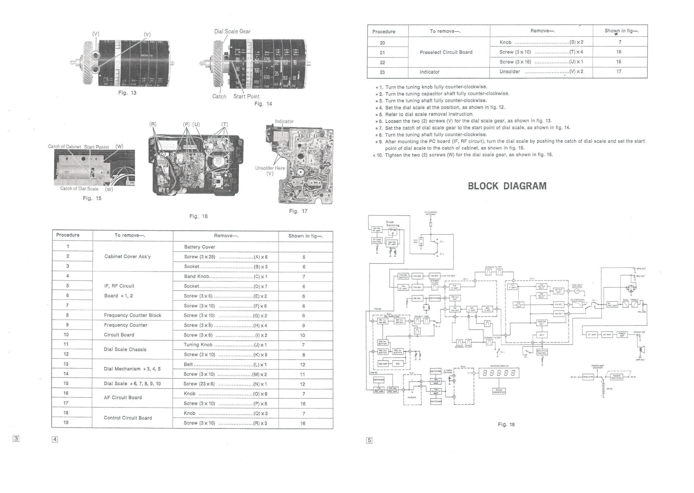
Dial
Scale
Gear
Catch
Start
Po
int
Fig.
14
Indicator
|
Catch
of
Dial
Scale
(WW)
Fig.
15
Fig.
16
Procedure
To
remove—.
Remove—.
Shown
in
fig—.
1
Battery
Cover
2
Cabinet
Cover
Ass’y
SCKEW
(3X25).
sezsavisssinenescines
ond
(A)
x6
5
3
SOCK
Ct
sissinsisaswensacawwssmpensawenisy
(B)x3
6
4
Balid!
Kn
ODiiiss.scins
sc
siissainaeescilaven
(C)x1
7
5
IF,
RF
Circuit SOCKEL,
.i:osicdnuessnenesheraramaanewnnne
(D)
x7
6
6
Board
«1,
2
SGrew!
(3:16)
sinsseasensansanneaiceesas
(E)
x2
6
7
SCrew
(S510)
ccasessneasesesseeses
(F)
x6
6
8
Frequency
Counter
Block
Screw
(3X10)
.........ceeeee
eee ees
(G)
x2
6
9
Frequency
Counter
Screw
(3
x6)
anid
isinsieindenesieteesmimse
(H)
x4
9
10
Circuit
Board
Screw
(3X6)!
siiscsscserseanvensaceecs
(I)x2
10
1
TUNING
KRAOD:
wiscsicasisineacanseieeiaaens
(J)
x1
7
Dial
Scale
Chassis
12
Screw
(3X10)
......scccsesesseeens
(K)x5
8
13
BGIE
snscapusisatipiniiscsmninnaadcncetnesead
(L)
x1
12
Dial
Mechanism
+3,
4,
5
14
SCrew
(SAO):
sdencctsnaseewoaeres
(M)
x2
11
15
Dial
Scale
x6,
7, 8,
9,
10
SCEW
(23'X'6)
sevssvsversonesovenrs
(N)
x1
12
16
NOD!
oui sic
cotisacnueesarsaniaecensns
(O)
x6
iA
AF
Circuit
Board
nA
Screw
(3510).
ssisvesscsewaevetieas
(P)x5
16
18
KNOB:
ssichivadaGimelasonenaneandengenuses
(Q)
x3
7
Control
Circuit
Board
19
Screw
(3X10)
....ccsceesesssseeees
(R)
x3
16
4
To
remove—.
Remove—.
Shown
in
fig—.
Procedure
20
T
Screw
(3
x
10)
16
Preselect
Circuit
Board
Screw
(3
x
16)
16
Indicator
Unsolder
17
«
1.
Turn
the
tuning
knob
fully
counter-clockwise.
x
2.
Turn
the
tuning
capacitor
shaft
fully
counter-clockwise.
«x
3.
Turn
the
tuning
shaft
fully
counter-clockwise.
«
4,
Set
the
dial
scale
at
the
position,
as
shown
in
fig.
12.
*
5.
Refer
to
dial
scale
removal
instruction.
«
6.
Loosen
the
two
(2)
screws
(V)
for
the
dial
scale
gear,
as
shown
in
fig.
13.
*
7.
Set
the
catch
of
dial
scale
gear
to
the
start
point
of
dial
scale,
as
shown
in
fig.
14.
«x
8.
Turn
the
tuning
shaft
fully
counter-clockwise.
x
9.
After
mounting
the
PC
board
(IF,
RF
circuit),
turn
the
dial
scale
by
pushing
the
catch
of
dial
scale
and
set
the
start
point
of
dial
scale
to
the
catch
of
cabinet,
as
shown
in
fig.
15.
*
10.
Tighten
the
two
(2)
screws
(W)
for
the
dial
scale
gear,
as
shown
in
fig.
15.
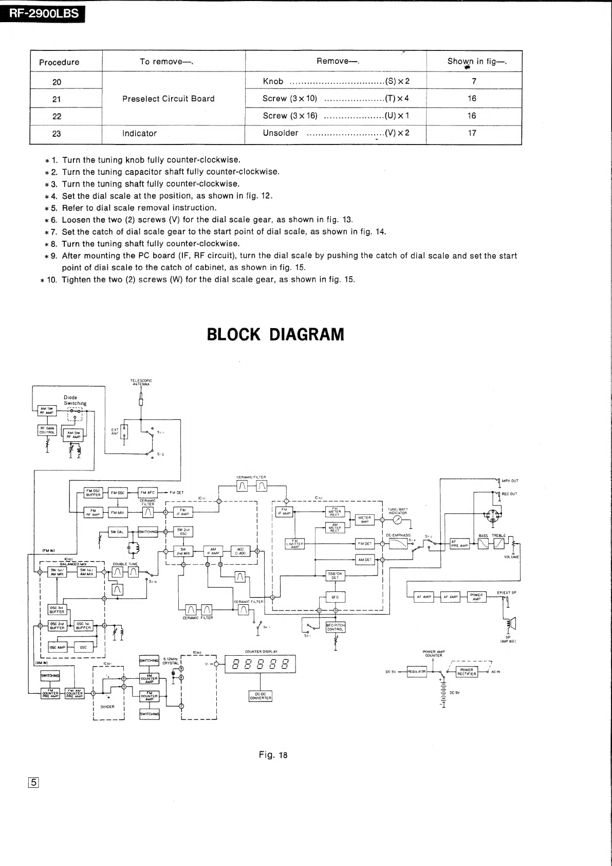
BLOCK
DIAGRAM
TELESCOPIC
ANTENNA
Diode
Switching
Eee
CERAMIC
FILTER
——
ra
q
MPX
OUT
FM
OSC
F
Fi
surrer
[|
FM
OSC
ol
c
(cw
yee
ad
101
2
CLT
ee
ee,
ee
2
2l=aseSaaaee
eee
FILTER
fr
©
| r
7
:
EM,
TUNE/BATT
FM
FM
EM.
TER
®
!
AMP
o)
(/)
o
aM
METER
|
RECT
DE-EMPHASIS
sre
BASS
TREBLE
FM
rss
°
AF
LIMITER
FM
DET
F—()
zz
PRE
AMP
‘AM
pt
aS
A
|
VOLUME
AM
DET
(2
TUNE
EP/EXT
SP
sP
(IMP
82)
POWER
AMP.
COUNTER
COUNTER
DISPLAY
oon
im
ae
ee
/ /
POWER
J
oc
5V
REGULATOR
Q
SH
arCTFIER
‘ACIN
° 8
2
2
eatuififife
+,
Fig.
18