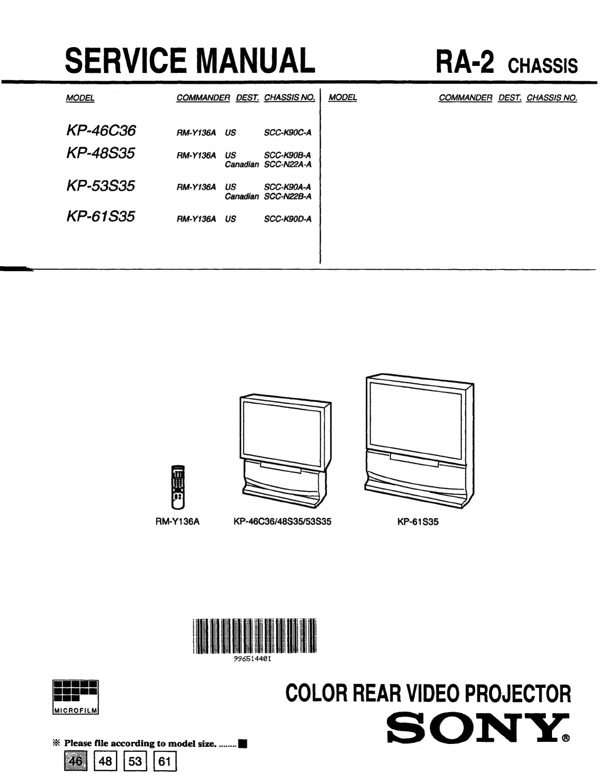
TABLE
OF
CONTENTS
Section
Title
Page
1.
GENERAL
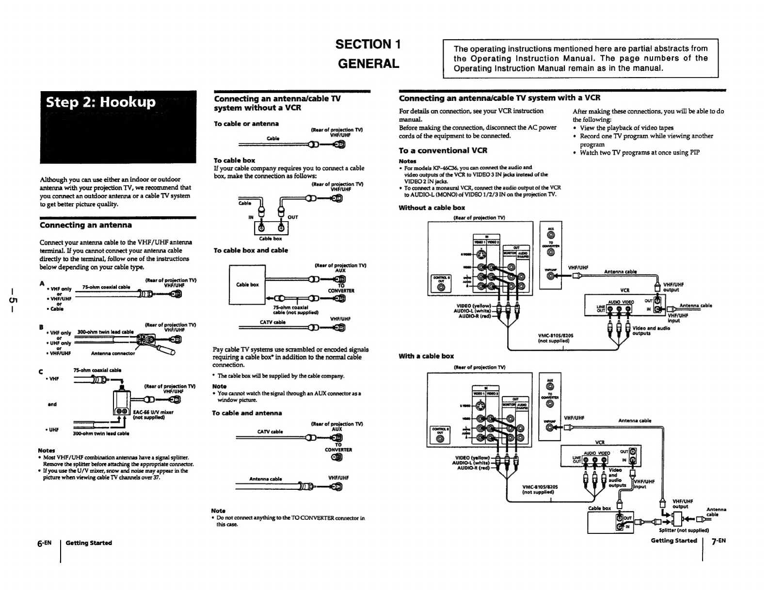
Step:2
s
HOOKUP
ic.
ccesccsccssetesdescacesnseoscosecacessonsetesecneossconsteeses
5
Step
3
:
Setting
up
the
remote
control
8
Step
4
:
Setting
up
the
projection
TV
automatically
(AUTO
SET-UP)
vacisssscovisiteccvedssttcsenstesssscesessnsessonsts
9
Changing
the
menu
language
....
11
Watching
the
TV
\..ccccsiscscscssscetssadecsevenesvssesesessosevecdecive
stcctens
11
Watching
two
programs
at
one
time
-
PIP
........scssssssosesesees
12
Freezing
the
picture
(FREEZE)
........cs.ssssscssccsescecesseeseseees
13
Adjusting
the
picture
(VIDEO)
..........csesssccsssesseneecesseseeeees
13
Adjusting
the
color
temperature
(TRINITONE)..............4
14
Selecting
the
video
mode
(VIDEO)
...........csssscccsssseesenenseers
14
Adjusting
the
sound
(AUDIO)
............:sscsssssssssseesseesenesaters
14
Using
audio
effect
(SSURROUND)...........ccsssssssseseeceeeeneees
15
Selecting
stereo
or
bilingual
programs
(MTS)..............+s000
15
Setting
the
speaker
switch
(SPEAKER)
............cssseeceseeeee
15
Setting
audio
out
(AUDIO
OUT)
.u.........ccscssssessesceseeseececenes
16
Setting
daylight
saving
time
(DAYLIGHT
SAVING)
.......
16
Setting
the
clock
(CURRENT
TIME
SET).............:ceccsseceees
16
Setting
the
timer
to
turn
the
projection
TV
on
and
off
(ON/OFF
TIMER)
...........ccccccccssscccssecsssetsnesetseseeeenes
17
Customizing
the
channel
names
(CHANNEL
CAPTION).
17
Blocking
out
a
channel
(CHANNEL
BLOCK)
.............000
18
Setting
your
favorite
channels
(FAVORITE
CHANNEL).
18
Setting
video
labels
(VIDEO
LABEL)
.........csscsesssereseeeees
18
Setting
Caption
Vision
(CAPTION
VISION)...........ssse00
19
Operating
video
equipMeNt
..........ccsccsccsssssesessessecessnsesesens
19
Operating
a
cable
box
or
DBS
receiver
.......csssseeseseseseeees
20
Troubleshooting
..........csessscssssssesecesescssesssesecessssessesessssssceess
21
Index
to
parts
and
CONTOIS
..........ssccsessssesesecesssseseesesneesssscsees
21
.
DISASSEMBLY
2-1.
Rear
Board
Removal
.......cccssssssssssesesesesssesesssesesesees
23
2-2.
Chassis
Assy
Removal
..........scccssssesssestseesserseeeees
23
2-3.
Service
Position
............cesssccsseesssssesesssscseessseseeneosees
23
2-4-1.
HA
Board
Removal
(KP-46C36)
......scssssssssssssseeeeees
24
2-4-2.
HA
Board
Removal
(KP-48S35/53S35/61S35)......
24
2-5-1.
Beznet
Assy
Removal
(KP-46C36/48S35/53S35)
..
24
Section
Title
Page
2-5-2.
Screen
Frame
Assy
Removal
(KP-61S35)
..............
24
2-6-1.
Mirror
Cover
Assy
Removal
(KP-46C36/48S35/53S35)
0...
cssesecesssssessetssseseceeeees
25
2-6-2.
Reflection
Mirror
Removal
(KP-61S35)...........0008
25
2-7.
_
High-Voltage
Cable
Installation
and
Removal
.......
25
2-8.
—
Picture
Tube
Removal
...........cccscssssscecssessesseseeeceeees
25
2-9-1.
Service
stay
Assy
How
to
use
and
Carry
Back
Service
stay
ASSY
........cssessceseseeseeseees
26
2-9-2.
Picture
Tube
Bracket
Assy
Removal
..........cccecee
26
2-9-3.
Seting
of
Service
stay
Assy
(KP-46C36/48S35/53S35)
.....csecesesssscesessssseeeesseeeeee
27
2-9-4.
Install
a
Chassis
Assy
................
:
27
3.
SET-UP
ADJUSTMENTS
......0......cccccccsseesseseeees
29
4.
SAFETY
RELATED
ADJUSTMENTS
..................
49
5.
CIRCUIT
ADJUSTMENTS
..........
cc
ecccscssseesssseeees
52
6.
DIAGRAMS
6-1.
Block
Diagrams
(1)
........ccsssesssssecccecseeseesceseeeceenes
56
Block
Diagrams
(2)
.......ss.scccscsccssscssssessersssnceetceseneas
59
Block
Diagrams
(3)
........ssscccsssssssessssseresecssseeceavees
61
6-2.
Frame
Schematic
Diagram
.............cssscsscssseseeeteneees
63
6-3.
—
Circuit
Boards
Location
..........ecssesssscseessesseseeesenees
66
6-4.
Printed
Wiring
Boards
and
Schematic
Diagrams....
66
@
AVBOAIG
sisssicsecesssssssceseassaenssssesesacheesdesscseaiseiatecilersts
¢
HA,
P
Boards
......
¢
ZR,
ZG
Boards...
©
G
Board
....ssscsscsscseees
¢CR,CG,CB
Boards.........
6-5.
SemiCONGUCTOTS
..........sseeeseesessetsncecsenceseteseenenenescees
7.
EXPLODED
VIEWS
7-1.
Cover
(KP-46C36/48S35/53S35)
......ssssssssssssssesssens
93
7-2.
Cover
(KP-61S35)
7-3.
Chassis
7-4.
Picture
Tube


 User manual")