Sony VPL-CX11 User manual

.............. ......... ....................
SERVICE MANUAL
.............. ......... ....................
MODEL DEST. CHASSIS NO. MODEL DEST. CHASSIS NO.
VPL-CX11 WORLD RM-PJM10 WORLD
DATA PROJECTOR

!WARNING
This manual is intended for qualified service personnel only.
To reduce the risk of electric shock, fire or injury, do not perform any servicing other than that
contained in the operating instructions unless you are qualified to do so. Refer all servicing to
qualified service personnel.
!WARNUNG
Die Anleitung ist nur für qualifiziertes Fachpersonal bestimmt.
Alle Wartungsarbeiten dürfen nur von qualifiziertem Fachpersonal ausgeführt werden. Um die
Gefahr eines elektrischen Schlages, Feuergefahr und Verletzungen zu vermeiden, sind bei
Wartungsarbeiten strikt die Angaben in der Anleitung zu befolgen. Andere als die angegeben
Wartungsarbeiten dürfen nur von Personen ausgeführt werden, die eine spezielle Befähigung
dazu besitzen.
!AVERTISSEMENT
Ce manual est destiné uniquement aux personnes compétentes en charge de l’entretien.Afin
de réduire les risques de décharge électrique, d’incendie ou de blessure n’effectuer que les
réparations indiquées dans le mode d’emploi à moins d’être qualifié pour en effectuer d’autres.
Pour toute réparation faire appel à une personne compétente uniquement.
WARNING!!
AN INSULATEDTRANSFORMER SHOULD BE USED DURING
ANY SERVICE TO AVOID POSSIBLE SHOCK HAZARD, BE-
CAUSE OF LIVE CHASSIS.
THE CHASSIS OFTHIS RECEIVER IS DIRECTLY CONNECTED
TO THE AC POWER LINE.
SAFETY-RELATED COMPONENT WARNING !!
COMPONENTSIDENTIFIED BY A !MARK ONTHESCHEMATIC
DIAGRAMS, EXPLODEDVIEWS AND INTHE PARTS LIST ARE
CRITICAL TO SAFE OPERATION. REPLACE THESE COMPO-
NENTSWITH SONY PARTSWHOSE PART NUMBERS APPEAR
AS SHOWN IN THIS MANUAL OR IN SUPPLEMENTS PUB-
LISHED BY SONY.
ATTENTION!!
AFIN D’ÉVITER TOUT RISQUE D’ÉLECTROCUTION
PROVENANT D’UN CHÂSSIS SOUS TENSION, UN
TRANSFORMATEURD’ISOLEMENT DOIT ETRE UTILISÉ LORS
DE TOUT DÉPANNAGE.
LE CHÂSSIS DE CE RÉCEPTEUR EST DIRECTEMENT
RACCORDÉ Á L’ALIMENTATION SECTEUR.
ATTENTION AUX COMPOSANTS RELATIFS Á LA
SÉCURITÉ!!
LES COMPOSANTS IDENTIFIÉS PAR UNE MAPQUE !SUR
LES SCHÉMAS DE PRINCIPE, LES VUES EXPLOSÉES ET LES
LISTES DE PIECES SONT D’UNE IMPORTANCE CRITIQUE
POUR LA SÉCURITÉ DU FONCTIONNEMENT. NE LES
REMPLACER QUE PAR DES COMPOSANTS SONY DONT LE
NUMÉRO DE PIÈCE EST INDIQUÉ DANS LE PRÉSENT
MANUEL OU DANS DES SUPPLÉMENTS PUBLIÉS PAR SONY.
For the customers in the Netherlands
Voor de klanten in Nederland
Bij dit produkt zijn batterijen geleverd.
Wanneer deze leeg zijn, moet u ze niet
weggooien maar inleveren als KCA.

1
VPL-CX11
Table of Contents
1. Service Informations
1-1. Board Layouts .............................................................................................1-1
1-1-1. Extension Boards and Extension Cables ....................................1-2
1-2. Disassembly ................................................................................................1-3
1-2-1. Top Cover Removal ...................................................................1-3
1-2-2. H Board Removal.......................................................................1-4
1-2-3. C Board Removal .......................................................................1-4
1-2-4. B and BA Boards Removal ........................................................1-5
1-2-5. Optics Unit Assy Removal .........................................................1-6
1-2-6. QA Board Removal....................................................................1-7
1-2-7. Power Block Removal................................................................1-8
1-2-8. Lens . Prism Assy and In-polarizer Panel Removal...................1-9
1-2-9. Lamp Assy Removal ..................................................................1-9
1-2-10. Extension Boards and Extension Cables Connection ..............1-10
1-2-11. Warning on Power Connection ................................................1-11
2. Electrical Adjustments
2-1. Preparations.................................................................................................2-1
2-1-1. Equipment Required...................................................................2-1
2-1-2. Factory Mode Setting .................................................................2-1
2-2. V-COM Adjustment....................................................................................2-1
2-3. Adjustment Item Initialize Data ..................................................................2-2
2-4. Service Kowhow .........................................................................................2-6
2-4-1. After Replacing the Prism Block ...............................................2-6
2-4-2. After Replacing the Board .........................................................2-6
2-5. White Balance Adjustment on Servicing ....................................................2-7
2-5-1. Signal Level Adjustment ............................................................2-7
2-5-2. White Balance Adjustment ........................................................2-7
2-6. Memory .......................................................................................................2-8
3. Semiconductors...................................................................................3-1

2VPL-CX11
4. Spare Parts
4-1. Notes on Repair Parts..................................................................................4-1
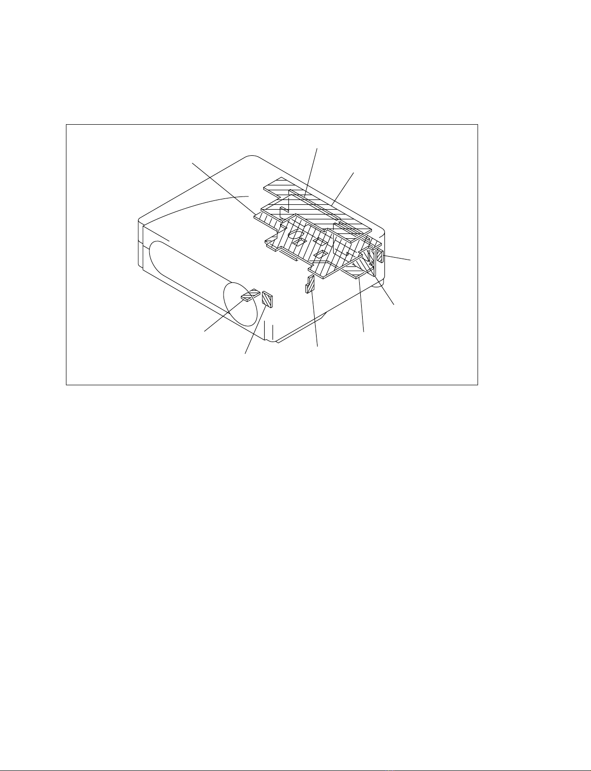
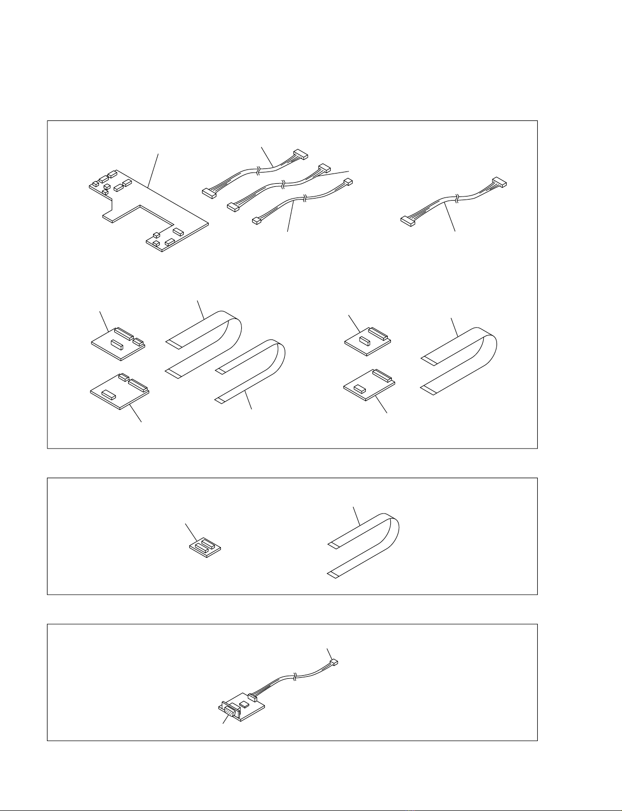
4-2. Exploded Views ..........................................................................................4-2
4-2-1. Cover ..........................................................................................4-2
4-2-2. Chassis........................................................................................4-3
4-2-3. Base ............................................................................................4-4
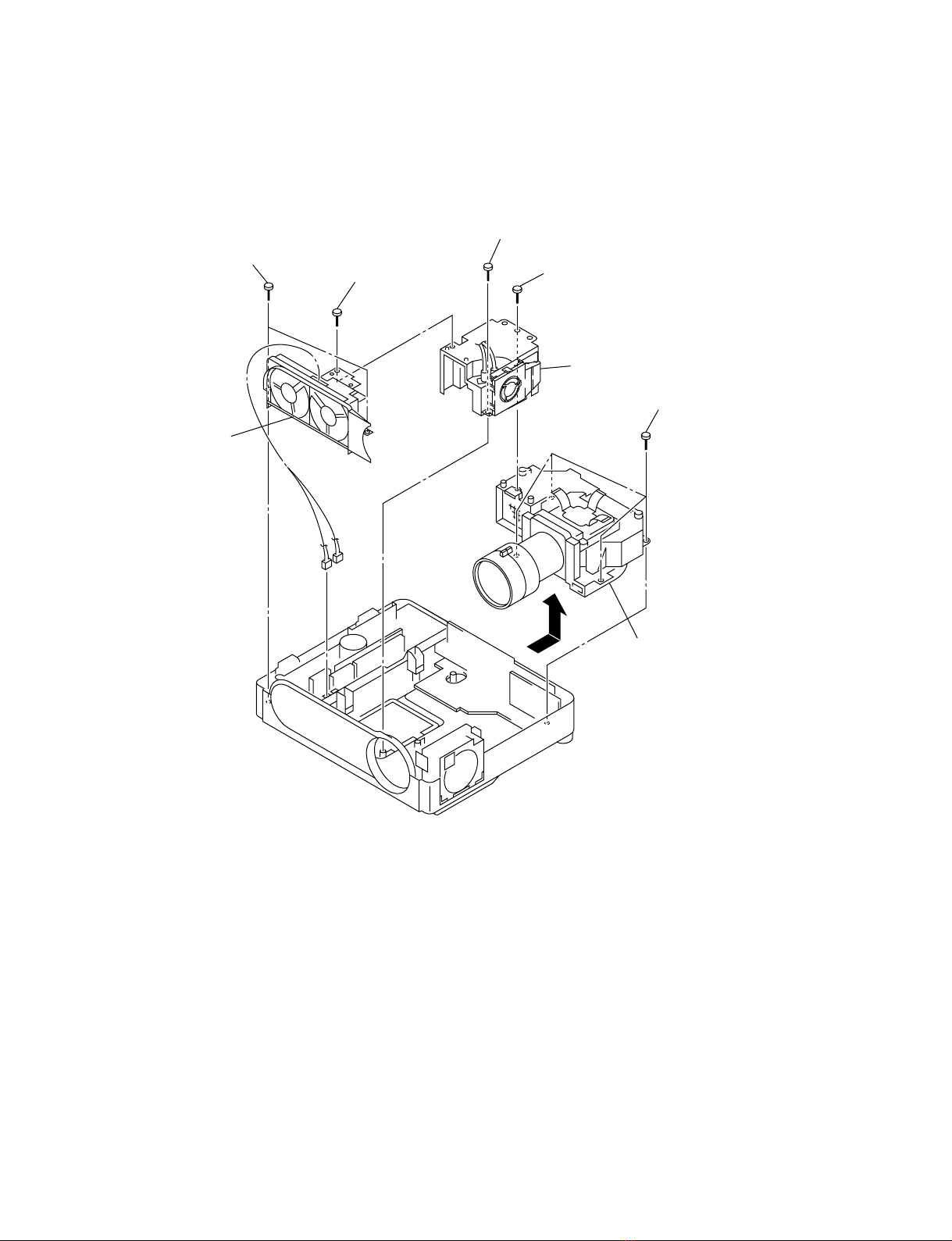
4-2-4. Optics .........................................................................................4-5
4-3. Electrical Parts List .....................................................................................4-6
4-4. Accessories................................................................................................4-20
5. Block Diagrams
QA ....................................................................................................5-1
B (1/2) ....................................................................................................5-2
B (2/2) ....................................................................................................5-3
BA ....................................................................................................5-4
C (1/2) ....................................................................................................5-5
C (2/2) ....................................................................................................5-6
Power ....................................................................................................5-7
6. Diagrams
6-1. Frame Schematic Diagram ..........................................................................6-2
6-2. Schematic Diagrams and Printed Wiring Boards........................................6-3
Schematic Diagrams
QA (1/2) ....................................................................................................6-4
QA (2/2) ....................................................................................................6-5
B (1/4) ....................................................................................................6-7
B (2/4) ....................................................................................................6-8
B (3/4) ....................................................................................................6-9
B (4/4) ..................................................................................................6-10
BA ..................................................................................................6-13
C (1/5) ..................................................................................................6-16
C (2/5) ..................................................................................................6-17
C (3/5) ..................................................................................................6-18
C (4/5) ..................................................................................................6-19
C (5/5) ..................................................................................................6-20
H, NF, NR, U, V .....................................................................................6-23
Printed Wiring Boards
QA ....................................................................................................6-3
B ....................................................................................................6-6
BA ..................................................................................................6-12
C ..................................................................................................6-14
H, NF, NR, U, V .....................................................................................6-22

1-1
VPL-CX11
Section 1
Service Informations
B
H
NR
BA
QA
V
NF
U
C
1-1. Board Layouts

1-2 VPL-CX11
1-1-1. Extension Boards and Extension Cables
X5 board
X2 board X4 board
X3 board
X1 board
Three X7 boards
Connector (11P)
Connector (10P)
Two connectors (8P)
Three connectors (3P)
Flexible cable (50P)
Three flexible cables (32P)
Flexible cable (50P)
Flexible cable (24P)
X kit assy (A-1501-785-A)
X7 kit assy (A-1501-787-A)
RS-232C
Quick Access Assy (A-1501-849-A)
Connector

1-3
VPL-CX11
3Two screws
(+B3 x6)
2Two screws
(+B3 x6)
1Filter cover assy
4Top cover
Claw
CN705
1-2. Disassembly
1-2-1. Top Cover Removal
n
When removing or installing the top cover, do not tilt the
top cover to the unit. It may cause malfunction. To avoid
any damages such as transistors on the BA board, make
sure that the top cover is level with the unit when removing
or installing the top cover.

1-4 VPL-CX11
3Eight screws
(+P2.6 x4)
4H board
2Cover (H)
Top cover
1Two screws
(+P2.6 x4)
CN002
1Four screws
(+P2.6 x4)
2C board
CN706
CN701 CN709
CN403
CN405
CN702
CN703
CN715
CN716
CN713
CN714
CN718
CN717
CN720
1-2-2. H Board Removal
1-2-3. C Board Removal

1-5
VPL-CX11
2B board
3BA board
1Two screws
CN105
CN103
CN104
1-2-4. B and BA Boards Removal
..
..
.Remove the C board. (Refer to Sec.1-2-3.)

1-6 VPL-CX11
1-2-5. Optics Unit Assy Removal
..
..
.Remove the C board. (Refer to Sec.1-2-3.)
1Two screws
(+P3 x6)
3Fan holder
8Optics unit assy
2Screw
(+P3 x6)
4
Screw
(+PSW3 x10)
5Screw
(+P2.6 x4)
6Lamp house
7Four screws
(+PSW3 x10)
CN25 CN24

1-7
VPL-CX11
1-2-6. QA Board Removal
..
..
.Remove the Optics unit assy. (Refer to Sec.1-2-5.)
2Five screws
(+PWH2.6 x4)
1Two screws
(+B2 x6)
3QA board
Plate (PS2)
Earth plate (QA)
CN101
CN102

1-8 VPL-CX11
1-2-7. Power Block Removal
4Four screws
(+P3 x6)
8Four screws
(+P3 x6)
9Power block
(Lamp)
Power bracket
2Two screws
(+PTPWH3 x8)
1Cover (PW)
5Power block assy
6Two claws
7Power block
3Connector (2P)
CN25 CN24
CN21
CN22
CN23
CN3 CN2
CN2
CN1
CN1

1-9
VPL-CX11
1-2-8. Lens ..
..
.Prism Assy and In-polarizer Panel Removal
..
..
.Remove the Optics unit assy. (Refer to Sec.1-2-5.)
1Two screws
3Three screws
2Top cover
5Polarizer panel spring
6In-polarizer panel (R)
7Polarizer panel spring
9Polarizer panel spring
8In-polarizer panel (G)
0In-polarizer panel (B)
4Lens .prism assy
1-2-9. Lamp Assy Removal
2Lamp door assy
4Lamp assy
3Loosen the screw
1Loosen the screw

1-10 VPL-CX11
1-2-10. Extension Boards and Extension Cables Connection
1
Remove the C board. (Refer to Sec.1-2-3.)
4Remove the QA board.
(Refer to Sec.1-2-6.)
2Remove the B board.
(Refer to Sec.1-2-4.)
5Fix the X5 board
instead of the C board.
3Remove the BA board.
(Refer to Sec.1-2-4.)
Flexible cable
(24P)
Flexible cable
(50P)
Three flexible
cables (30P)
Flexible cable
(50P)
X3 board X1 board
BA board
X5 board
B board
C board
X4 board X2 board
Three X7 boards
QA board Connector (8P)
Connector (11P)
Connector (3P)
Connector (10P)
Connector (3P)
Connector (8P)
Connector (3P)
To power block(CN21)

1-11
VPL-CX11
1-2-11. Warning on Power Connection
Use the appropriate rating cord and plug that are applied to local regulations as shown in below tables.
The United Continental UK, Ireand, Japan
States, Canada Europe Australia, Newzealand
Plug type VM0233/290B YP-12A Note: YP332
Female end VM0089/386A YC-13B VM0310B YC-13
Cord type SJT H05VV-F N13237/C0-228 VCTF
Rated Voltage & Current 10 A/125 V 10 A/250 V 10 A/250 V 7 A/125 V
Safety approval UL/CSA VDE VDE DENTORI
Note: Use the appropriate rating plug which is applied to local regulations.


2-1
VPL-CX11
Section 2
Electrical Adjustments
2-2. V-COM Adjustment
1. Input the green-only 1H inverted signal to INPUT-A.
2. Set the CONTRAST to 50 and BRIGHT to 50.
3. Set the screen to G VCOM adjustment of [Device
Adjust].
Adjust the G VCOM so that the flicker on the screen is
the minimum.
4. Input the red-only and blue-only 1H inverted signal
respectively and adjust R VCOM and B VCOM
respectively so that the flicker becomes minimum.
5. Store the adjustment value in the memory.
6. Select the projection of vertically reversed from the
front [CEIL. FRT] using the menu screen.
7. Enter the G VCOM adjustment screen of the [Device
Adjust]. Adjust for the same value as step 3.
8. Connect the 1H-inverted single color signal of red then
blue to the input connector. Adjust for the same value
as step 4 using the R VCOM and B VCOM
respectively.
9. Store the adjustment value in the memory.
2-1. Preparations
2-1-1. Equipment Required
..
..
.Oscilloscope
Tektronix 2465 or equivalent
(bandwidth: 350 MHz or more)
..
..
.NTSC, PAL, SECAM component signal generator
Tektronix TG2000 +AVG1 (optional module) +
AWVG1 (optional module) or equivalent
..
..
.VG (Programmable video signal generator)
VG814 or equivalent
..
..
.Digital voltmeter
Advantest TR6845 or equivalent
..
..
.Luminance meter
Note : Perform the following adjustments at least 5 minutes after turning on
the power.
2-1-2. Factory Mode Setting
1. Make sure that the STATUS in the menu is ON.
2. Exit the menu.
3. Press the keys in the following ORDER:
“ENTER” →“ENTER” →“LEFT” →“ENTER”
4. The message “Do you wish to enter into the FACTO-
RY MODE?” will be displayed.
5. Select YES.

2-2 VPL-CX11
Menu Title Item Name
Memory Name
SET CH MEMORY STATUS W/B MEMOR
MEMORY VIDEO S VIDEO INPUT-A MEMORY VIDEO VIDEO RGB RGB
HIGH LOW HIGH LOW
PICTURE CTRL CONTRAST 80 80 80
BRIGHT 50 50 50
COLOR 50 50 50
HUE 50 50 50
SHARP 50 50 50
D.PICTURE OFF OFF OFF
COLOR TEMP LOW LOW HIGH
COLOR SYS AUTO AUTO —
GAMMA MODE ——GRAPHICS
INPUT SETTING ASPECT 4 : 3 (*)
SIZE H *
SHIFT *
SCAN CONV ON (*)
DOT PHASE 15 (*)
SET SETTING STATUS ON
INPUT-A RGB
KEYSTONE MEMORY ON
DIGITAL KEYSTONE OFF
LANGUAGE ENGLISH
INSTALLATION
FLOOR-FRONT
POWER SAVING OFF
SIRCS RECEIVER FRONT&REAR
LAMP TIMER
INDICATION ONLY
INFORMATION fH
INDICATION ONLY
fV
INDICATION ONLY
ROM Ver
INDICATION ONLY
OPERATION TIMER
INDICATION ONLY
PREVIOUS LAMP TIMER
INDICATION ONLY
W/B ADJUST GAIN R 64 64 64 64
GAIN G 64 60 64 60
GAIN B 64 60 64 60
BIAS R 128 128 128 128
BIAS G 128 128 128 128
BIAS B 128 128 128 128
* : DOT PHASE, SIZE H, SHIFT H/V, SCAN CONV and ASPECT, in the “INPUT SETTING”menu have an initial value respectively in
accordance with the input signal (PRESET MEMORY No.).
Note : There are nonadjustable items in accordance with the input signal.
VOLUME 50 50 50
2-3. Adjustment Item Initialize Data
VPL-CX11

2-3
VPL-CX11
Menu Title Item Nam
Memory Name
SET CHROMA MEMORY Reso Status Remarks
MEMORY NT358,NT443 PAL,PALM/N YUV Memory Memory
B&W60 SECAM,B&W 50
RGB MTRX/ CONTRAST 45 47 47
BRIGHT 35 35 35 Fixed Value
SUB HUE 6 8 7
SUB BRT 6 6 7 Fixed Value
R-Y/R 12 10 11
R-Y/B 12 12 13
G-Y/R 7 6 6
G-Y/B 7 6 5
VIDEO CON 9 9 7
VIDEO COL 7 6 7
YUV CON 7 7 7
YUV COL 7 7 7
SUB SHP 1 1 2 Fixed Value
SHP FO 3 3 3 Fixed Value
PRE OVER 0 0 2 Fixed Value
NR LVL 0 0 0 Fixed Value
CEC LVL 2 2 2 Fixed Value
DMIC PIC 2 Fixed Value
DCOM/ VENH 1 Fixed Value
CHROMA/ PAL DVD
Non Adjustable
Fixed Value
Y-OUT LVL 15
C-OUT LVL 29
Y-DL *3Fixed Value
S B-Y ADJ 0 Fixed Value
S R-Y ADJ 3 Fixed Value
S-INHBT 0 Fixed Value
S-ID 0 Fixed Value
S GP 0 Fixed Value
S V-ID 0 Fixed Value
BELL f0 0 Fixed Value
BELL/HPF 0 Fixed Value
SHP GAIN 10 10 10 Fixed Value
SHIP EQ 0 0 0 Fixed Value
SHIP F0 2 2 2 Fixed Value
*1 : DOT PHASE, SIZE H, SHIFT H/V, SCAN CONV and ASPECT, in the “INPUT SETTING”menu have an initial value respectively in
accordance with the input signal (PRESET MEMORY No.).
*2 : It differs in accordance with the resolution of the input signal.
*3 : It changes depending upon the type of input signal.
*4 : It changes depending upon the installation setup. (Floor or Ceiling)
Note : There are nonadjustable items in accordance with the input signal.
VPL-CX11

2-4 VPL-CX11
Memory Name
Menu Title Item Name SET CHROMA MEMORY Reso Status Remarks
MEMORY NT358,NT443 PAL,PALM/N YUV Memory Memory
B&W60 SECAM, B&W 50
P. DRV/ VCOM G 55/55 *4
VCOM R 55/55 *4
VCOM B 55/55 *4
SIG CEN 160 Fixed Value
SID LVL 149
PRG LVL 110
INSTALLATION Non Adjustable
SH/ SH 1 4
SH 2 22
V AMP CONT 160
SUB CONT R 138
SUB CONT G 128
SUG CONT B 120
BRT1 120 Fixed Value
BRT2 Non Adjustable Fixed Value
EP/ VNRSH R Non Adjustable
VNRSH G Non Adjustable
VNRSH B Non Adjustable
VNRSL R Non Adjustable
VNRSL G Non Adjustable
VNRSL B Non Adjustable
TG/ DXOUT R Non Adjustable
DXOUT G Non Adjustable
DXOUT B Non Adjustable
ENB R Non Adjustable
ENB G Non Adjustable
ENB B Non Adjustable
ENB WIDTH Non Adjustable
YOUT Non Adjustable
DYOUT POS Non Adjustable
SH WIDTH Non Adjustable
CLP1 POS Non Adjustable
CLP1 WIDTH Non Adjustable
CLP2 POS Non Adjustable
CLP2 WIDTH Non Adjustable
VPL-CX11
Other manuals for VPL-CX11
1
This manual suits for next models
1
Table of contents
Other Sony Projector manuals

Sony
Sony Superlite VPL-CX6 User manual

Sony
Sony VPH-1041Q User manual

Sony
Sony KPR-46CX25 User manual

Sony
Sony VPL-PHZ12 Service manual

Sony
Sony VPL-SC50E User manual

Sony
Sony VPL-VW520ES Service manual

Sony
Sony VPL-FX52 User manual

Sony
Sony VPL-FX52 User manual

Sony
Sony VPL-FH65 User manual

Sony
Sony VPD-S1800Q User manual

Sony
Sony VPL-FH31 User manual

Sony
Sony SRXT615 Guide

Sony
Sony VPL-SW535 Installation and operation manual

Sony
Sony VPL-EW276 Service manual

Sony
Sony VPLSW525 User manual

Sony
Sony VPL-FH500L User manual

Sony
Sony VPH-1001Q User manual

Sony
Sony HDMI VPL-FH300L User manual

Sony
Sony VPL-EX50 User manual

Sony
Sony VPL-SX125 Service manual