Sony VPL-FHZ75 User manual

5-002-992-13 (1)
© 2019 Sony Corporation
Data
Projector
Operating Instructions
Before operating the unit, please read this manual and supplied Quick Reference Manual
thoroughly and retain it for future reference.
VPL-FHZ75/FHZ70
Not all models are available in all countries and area. Please check
with your local Sony Authorized Dealer.

2
Table of Contents
Overview
Location and Function of Controls .... 4
Main Unit ..................................... 4
Terminals ..................................... 5
Remote Commander and Control
Panel ......................................... 6
Preparation
Connecting the Projector ................... 8
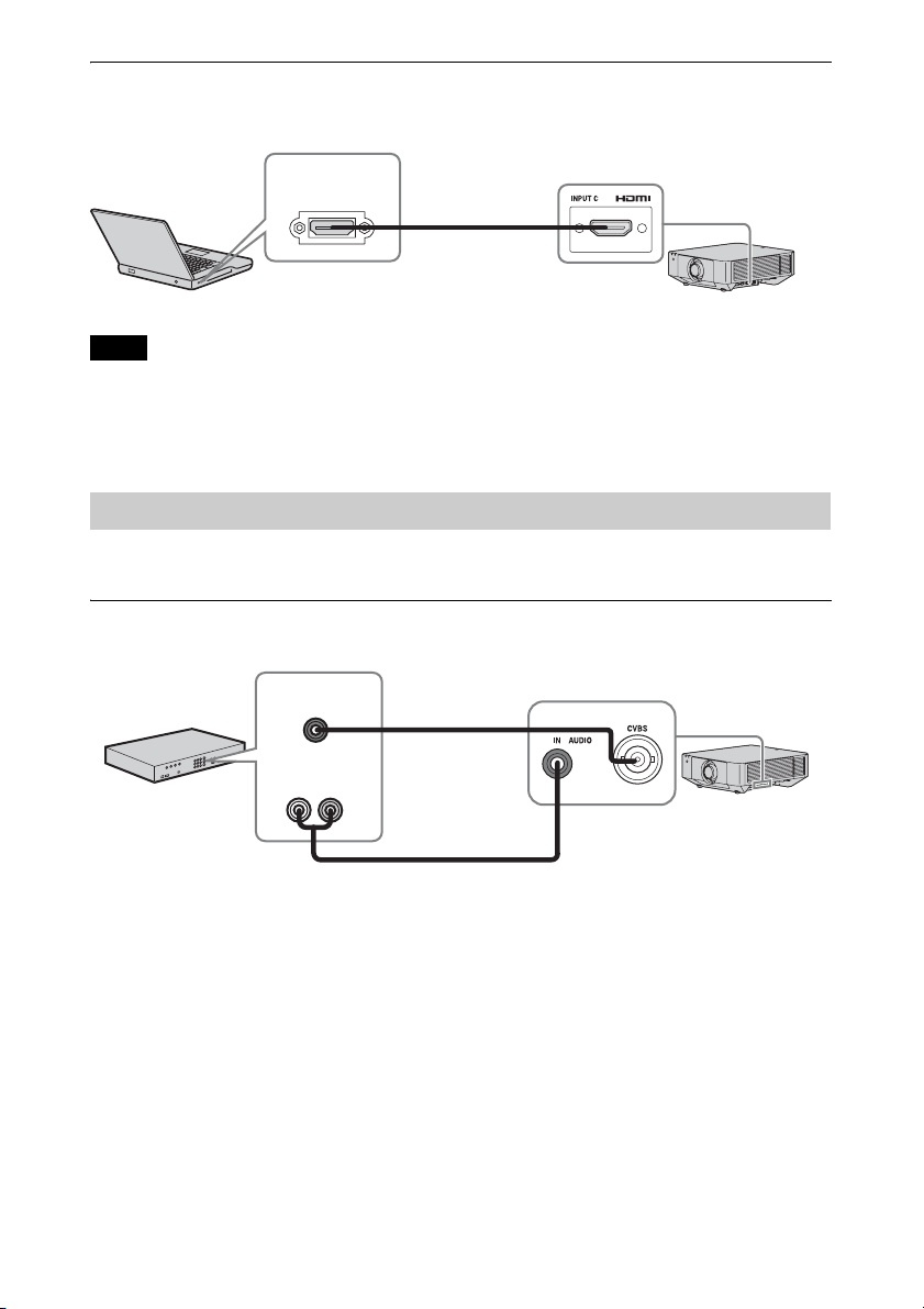
Connecting a Computer ............... 8
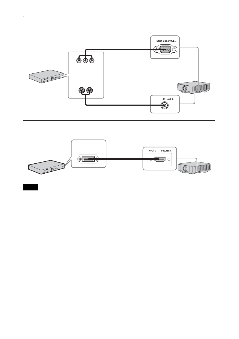
Connecting Video Equipment ...... 9
Connecting an External Monitor
and Audio Equipment ............. 11
Connecting Network
Equipment .............................. 12
Connecting to HDBaseT™
Equipment .............................. 13
Attaching the terminal cover ...... 15
Projecting/Adjusting an
Image
Projecting an Image ......................... 16
Adjusting the Focus, Size, and
Position of the Projected
Image ...................................... 17
Correcting for Trapezoidal
Distortion of the Projected
Image (Keystone
Adjustment) ............................ 18
Correcting Image Twist (Warp
Correction Feature) ................. 19
Blending Projections from
Multiple Projectors on a
Screen ..................................... 21
Turning Off the Power ................22
Using Convenient Functions ............22
Enlarging a Part of the Image
(Digital Zoom Function) .........22
Projecting Images with Two
Pictures Simultaneously (Two-
Picture Display Function) .......22
Setting the energy-saving mode
(ECO mode) ............................23
Adjustments and Settings
Using a Menu
Using a Menu ...................................24
Projection Setting Menu .................. 25
The Screen Menu .............................28
The Function Menu ..........................31
The Operation Menu ........................32
The Connection/Power Menu ..........34
The Installation Menu ......................36
The Information Menu .....................40
Network
Using Network Features ...................41
Displaying the Control Window
of the Projector with a Web
Browser ................................... 41
Confirming the Settings for the
Projector ..................................42
Operating the Projector from a
Computer .................................42
Using the e-mail Report
Function ..................................43
Configure the Network
Settings .................................... 45

3
Setting the Control Protocol of
the Projector ........................... 46
Others
Indicators ......................................... 49
Messages List .................................. 51
Troubleshooting ............................... 52
Cleaning the Air Filter ..................... 55
Replacing the Projection Lens ......... 56
Removing ................................... 56
Attaching .................................... 57
Specifications .................................. 58
Projection Distance and Lens Shift
Range ........................................... 65
Dimensions ...................................... 68
About Trademarks ........................... 69

4
BOverview
Location and Function of Controls
aLens (page 56)
bFront panel
cSide cover (page 55)
dVentilation holes (intake)
eVentilation holes (exhaust)
Do not place anything near the ventilation
holes as this may cause internal heat
buildup. Do not place your hand near the
ventilation holes (exhaust) and the
circumference as this may cause injury.
fTerminals (page 5)
gFront feet (adjustable) (page 18)
hLENS RELEASE button
(page 56)
iRemote control receiver
The remote control receivers are located
at the front and rear of the projector.
jON/STANDBY indicator
(page 49)
kWARNING indicator (page 49)
lControl panel (page 6)
mAntitheft lock
Connects to an optional antitheft cable
manufactured by Kensington.
For details, visit the Kensington’s web
site.
http://www.kensington.com/
nAntitheft bar
Connects to a commercially available
antitheft chain or wire.
Main Unit
Caution

5
Input (page 8)
aINPUT A
Video: RGB/YPBPRinput terminal
(RGB/YPBPR)
Audio: Audio input terminal (AUDIO)
bINPUT B
Video: DVI-D input terminal (DVI-D)
Audio: Audio input terminal (AUDIO)
cINPUT C
Video: HDMI input terminal (HDMI)
Audio: HDMI input terminal (HDMI)
dINPUT D
HDBaseT terminal
eVIDEO (VIDEO IN)
Video: Video input terminal
Audio: Audio input terminal (AUDIO)
• The audio input terminals of the projector are
for output to external equipment. Connect
external audio equipment to output audio
(page 11).
• The audio inputs of INPUT A, INPUT B, and
VIDEO are shared.
Output (page 11)
fOUTPUT A
Video: RGB/YPBPRoutput terminal
(RGB/YPBPR)
gOUTPUT B
Video: DVI-D output terminal (DVI-D)
hAUDIO OUT
Audio: Audio output terminal (AUDIO)
These terminals output projected images or
audio. As for images, the signal input from
INPUT A is output from OUTPUT A, and the
signal input from INPUT B is output from
OUTPUT B. However, if the signal input from
INPUT B is protected by HDCP, the signal is
not output from OUTPUT B. As for audio,
when INPUT A or B, or VIDEO is selected, the
audio signal input from the audio input
terminal is output; when INPUT C or D is
selected, the audio signal input from the
selected input terminal is output.
Others
iRS-232C terminal
RS-232C compatible control terminal
jLAN terminal (page 12)
kCONTROL S input terminal (DC
power supply) (CONTROL S)
Connects to the CONTROL S output
terminal on the supplied Remote
Commander with a connecting cable
(stereo mini plug (not supplied)) when
using it as a wired Remote Commander.
You do not need to install batteries in the
Remote Commander, as the power is
supplied from this terminal.
lAC IN (-) socket
Connects the supplied AC power cord.
Terminals
Notes
Note

6
Remote Commander
Control Panel
a?(On) key/1(Standby) key
Turns on the projector or enters the
standby mode.
bINPUT key/Direct input select
keys
Select an input signal (page 16).
Select the VIDEO (VIDEO IN) signal
with the INPUT key.
The E, F, and G keys are not used with
this projector.
cTWIN (Twin Picture) key
Simultaneously projects images from
two input signals on the screen as a main
picture and subpicture (page 22).
dPICTURE MODE key
Switches the “Picture Mode” setting
(page 25).
When “Intelligent Setting” in the
Projection Setting menu is set to “On,”
“Picture Mode” cannot be set (page 25).
eMENU key/ENTER key/V/v/B/b
(arrow) keys/RETURN key/
RESET key
Used for menu operation (page 24).
fFOCUS key
Used when the electric focus lens is
attached (page 17).
ZOOM key
Used when the electric zoom lens is
attached (page 17).
LENS SHIFT/SHIFT key (page 17)/
PATTERN key (page 18)/
KEYSTONE key (page 18)
Used for adjusting the projected image.
gVOLUME key
Adjusts the volume output from the
audio output terminal of the projector.
hASPECT key
Changes the aspect ratio of the projected
image (page 30).
iAPA (Auto Pixel Alignment) key
Automatically adjusts a picture to its
clearest while a signal from a computer
is input via the RGB input terminal
(INPUT A). You can cancel the
adjustment by pressing the APA key
again while adjusting.
Remote Commander and Control Panel
Note

7
jMUTING key
Mutes the audio output. Press again to
restore the previous volume.
kBLANK key
Temporarily cuts off the image. Press
again to restore the image.
lFREEZE key
Pauses a projected image. Press again to
restore the image. Use this key when
inputting a computer signal.
mD ZOOM (Digital Zoom) key
Enlarges a part of the image while
projecting (page 22).
nPOSITION (Picture Position) key
Not in use for the projector.
oInfrared transmitter
pID MODE switch (page 32)
Set an ID mode of the Remote
Commander. If you assign a different ID
number to each projector when multiple
projectors are used, you can control only
the projector with the same ID mode as
that of the Remote Commander.
qCONTROL S output terminal
Connect to the CONTROL S input
terminal on the projector with a
connecting cable (stereo mini plug (not
supplied)) to use the Remote
Commander as a wired one.
You do not need to install batteries in the
Remote Commander, as the power is
supplied from the projector.
rECO MODE key
Used for energy-saving mode setting
(page 23).
About Remote Commander operation
• Direct the Remote Commander toward the
remote control receiver.
• The shorter the distance between the
Remote Commander and the projector is,
the wider the angle within which the
Remote Commander can control the
projector becomes.
• If there is any obstruction between the
Remote Commander and the remote
control receiver on the projector, the
projector may not be able to receive
signals from the Remote Commander.

8
BPreparation
Connecting the Projector
• Turn off all equipment before making any connections.
• Use the proper cables for each connection.
• Insert the cable plugs firmly; Loose connections may reduce performance of picture signals or
cause a malfunction. When pulling out a cable, be sure to grip it by the plug, not the cable itself.
• For more information, refer also to the instruction manuals of the equipment you are connecting.
• Use a no-resistance audio cable.
Connection with a computer is explained for each input signal.
INPUT A
For connecting a computer with an RGB output terminal.
It is recommended that you set the resolution of your computer to 1920 × 1200 pixels for the external
monitor.
INPUT B
For connecting a computer with a DVI-D output terminal.
Notes
Connecting a Computer
Note
Mini D-sub 15-pin
cable
(not supplied)
Audio cable
(Stereo mini plug)
(not supplied)
RGB output
terminal
Audio output
terminal
Computer
DVI-D cable
(not supplied)
DVI-D output
terminal
Computer
Audio output
terminal
Audio cable
(Stereo mini plug)
(not supplied)

9
INPUT C
For connecting a computer with an HDMI output terminal.
• Use HDMI-compatible equipment which has the HDMI Logo.
• Use a high speed HDMI cable(s) on which the cable type logo is specified. (Sony products are
recommended.)
• The HDMI terminal of this projector is not compatible with DSD (Direct Stream Digital) signal or
CEC (Consumer Electronics Control) signal.
Connections with a VHS videocassette recorder, DVD player, or BD player are explained for
each input signal.
VIDEO IN
For connecting video equipment with a video output terminal.
Notes
Connecting Video Equipment
HDMI cable
(not supplied)
HDMI output
terminal
Computer
Video – BNC cable
(not supplied)
Audio cable (Phono plug × 2 – stereo mini plug) (not supplied)
Video output
terminal
Audio output
terminal
Video equipment

10
INPUT A
For connecting video equipment with a YPBPRoutput terminal.
INPUT C
For connecting video equipment with an HDMI output terminal.
• Use HDMI-compatible equipment which has the HDMI Logo.
• Use a high speed HDMI cable(s) on which the cable type logo is specified. (Sony products are
recommended.)
• The HDMI terminal of this projector is not compatible with DSD (Direct Stream Digital) signal or
CEC (Consumer Electronics Control) signal.
Notes
Component – Mini D-
sub 15-pin cable (not
supplied)
Audio cable (Phono plug
× 2 – stereo mini plug)
(not supplied)
Video equipment
YPBPRoutput
terminal
Audio output
terminal
HDMI cable
(not supplied)
Video equipment
HDMI output
terminal

11
To fix the HDMI cable
Fix the cable to the cable tie holders at the sides of the terminals using a commercially available
cable tie, as shown in the illustration.
Use a cable tie of less than 1.9 mm × 3.8 mm in thickness.
Projected images and input audio can be output to display equipment such as a monitor and
audio equipment such as speakers with a built-in amplifier.
OUTPUT A
This terminal outputs projected images. The images are output when a computer signal or video
signal is input from the RGB/YPBPRinput terminal (INPUT A).
Connecting an External Monitor and Audio Equipment
Cable tie (commercially available)
Cable tie holders
Note
Mini D-sub 15-
pin cable
(not supplied)
RGB input
terminal
Display equipment

12
OUTPUT B
This terminal outputs projected images. The images are output when a computer signal is input
from the DVI-D input terminal (INPUT B). However, if the signal input from INPUT B is
protected by HDCP, the signal is not output to OUTPUT B.
AUDIO output
When INPUT A or B, or VIDEO is selected, the audio input from the audio input terminal is
output; when INPUT C or D is selected, the audio input from the selected input terminal is
output.
Connecting network equipment
LAN terminal
• When using network features via the LAN terminal, be sure to check if “LAN Setting” is set to
“LAN Port” (page 34).
• Connect the projector to the network that is constructed to control the access from the internet,
such as LAN. If the projector is connected directly to the internet, the security risk is increased.
Note
Connecting Network Equipment
Notes
Display equipment
DVI-D input
terminal DVI-D cable (not
supplied)
Audio equipment
Audio input
terminal Audio cable (stereo mini
plug) (not supplied)
Computer
LAN
terminal
LAN cable (straight type) (not supplied)
Hub, router, etc

13
For connecting the computer, video equipment, and network equipment via the HDBaseT
transmitter.
Connecting to the computer
INPUT D
Connecting to video equipment
INPUT D
Notes for connecting this unit and the HDBaseT transmitter
• Ask a professional or Sony dealer to perform wiring. If wiring is not correct, the transmission
characteristics of the cable will not be achieved, and image or sound may break up or you
may experience unstable performance.
• Connect the cable directly to the HDBaseT transmitter without going through a hub or router.
• Use cables that meet the following conditions.
- CAT5e or higher
- Shielded type (covering connectors)
- Straight wire connection
-Singlewire
• When installing the cables, use a cable tester, cable analyzer, or similar device to check if the
cables meet the CAT5e or higher requirement. If there is a transit connector between this unit
and the HDBaseT transmitter, include it when measuring.
• To reduce the affect of noise, install and use the cable in a manner where it is not rolled up
and it is as straight as possible.
• Install the cable away from the other cables (especially the power cable).
• When installing multiple cables, do not bind them and keep the running parallel distance as
short as possible.
Connecting to HDBaseT™ Equipment
Computer
HDMI output
terminal
HDMI cable (not supplied)
HDBaseT transmitter
LAN cable: STP type (CAT5e or
higher, straight, not supplied)
Video equipment
HDMI output
terminal
HDMI cable (not supplied)
HDBaseT transmitter
LAN cable: STP type (CAT5e or
higher, straight, not supplied)

14
• The transmittable distance of the cable is 100 m (approx. 328 feet) maximum. If it exceeds
100 m (approx. 328 feet), it may cause the image or the sound to break up, or cause a
multifunction in LAN communication. Do not use the HDBaseT transmitter beyond the
transmittable distance.
• Inquire about operation or function problems caused by other manufacturer’s devices with
the relevant manufacturer.
Connecting to network equipment
For connecting to network equipment via the HDBaseT terminal to control the projector.
• When using network features, be sure to check if “LAN Setting” is set to “via HDBaseT”
(page 34).
• Connect this unit and the HDBaseT transmitter directly without a hub or router.
• Set “Extron XTP” in the Connection/Power menu to “On” when connecting to XTP Systems
manufactured by Extron Electronics (page 34).
Notes
Computer
LAN
terminal
Wired connection
LAN cable (straight type)
(not supplied)
Hub, wireless router
HDBaseT transmitter
Tablet PC/Smartphone
Computer
Wireless connection
LAN cable: STP type (CAT5e or
higher, straight, not supplied)

15
You can attach the supplied terminal cover to
prevent dust from entering the terminals to
maintain a neat appearance.
1Fit one shaft on the side of the terminal
cover into the hole on the bottom, then
fit the other shaft by bending the cover
slightly.
2Close the terminal cover.
Close the terminal cover until the two
tabs on the terminal cover click.
The terminal cover may not be attached
depending on the installation method, such
as due to the condition of the connected
cables or when installing the unit on the
floor. However, this has no impact on normal
use.
Opening the terminal cover
Raise the cover by inserting your fingers into
the finger hooks.
Attaching the terminal cover
Tab s
Shaft
Shaft
Openings for cables
Finger hooks
Note
Example of the cable layout in the cover

16
BProjecting/Adjusting an Image
Projecting an Image
The size of a projected image depends on the distance between the projector and screen. Install
the projector so that the projected image fits the screen size. For details on projection distances
and projected image sizes, see “Projection Distance and Lens Shift Range” (page 65).
1Plug the AC power cord into a wall
outlet.
2Connect all equipment to the projector
(page 8).
3Turn on the projector.
Press the ?/1key on the main unit or the
?key on the Remote Commander.
4Turn on the connected equipment.
5Select the input source.
Press the INPUT key on the projector to
display the input select window. Press
the INPUT key repeatedly or the V/v
key to select an image to be projected.
The signal icon appears on the right
side in the input select window when a
signal is input.
You can select the input source using
Direct input select keys on the Remote
Commander (page 6).
6Switch your computer to output to
external display by changing your
computer’s setting.
How to switch the computer to output to
the projector varies, depending on the
type of computer.
(Example)
7Adjust the focus, size, and position of
the projected image (page 17).
Computer
Video equipment
Projector
Wall outlet
1
2
3
5
4
6
Input select window
5
+

17
Adjusting the Focus, Size, and Position of the Projected Image
Focus Size (Zoom) Position (Lens shift)
When attaching the Electric
focus lens
Press the FOCUS key on the
projector or the Remote
Commander then press the V/
v/B/bkey to adjust the focus.
When attaching the Manual
focus lens
Turn the focus lever and
peripheral focus ring to adjust
the focus.
You can adjust the focus of
the peripheral area by rotating
the peripheral focus ring.
When attaching the Electric
zoom lens
Press the ZOOM key on the
projector or the Remote
Commander then press the V/
v/B/bkey to adjust the size.
When attaching the Manual
zoom lens
Turn the zoom lever to adjust
the size.
Press the LENS SHIFT/SHIFT
key on the projector or the
Remote Commander then press
the V/v/B/bkey to adjust the
position.
To return the lens to the center
position of the projected image
Press the RESET key on the
Remote Commander while
adjusting.
Focus lever
Peripheral focus ring
Zoom lever

18
Adjusting the tilt of the projector
with the front feet (adjustable)
When the projector is installed on an uneven
surface, you can adjust using the front feet
(adjustable).
• Be careful not to let the projector down on
your fingers.
• Do not push hard on the top of the projector
with the front feet (adjustable) extended. It
may cause a malfunction.
Displaying a pattern for adjusting
an image
You can display a pattern for adjusting the
projected image with the PATTERN key on
the Remote Commander. Use V/v to change
the pattern and B/b to change its color.
Press the PATTERN key again to restore the
previous image.
If the screen is tilted, or you are projecting
from an oblique angle, perform keystone
adjustment.
If the projected image is
trapezoidally-distorted in the
vertical plane
1Press the KEYSTONE key on the
Remote Commander once or select
“Screen Fitting” in the Installation
menu (page 36).
The “Screen Fitting” menu is displayed.
2Select “V Keystone.”
3Adjust the value using B/b.
The higher the setting, the narrower the
top of the projected image. The lower
the setting, the narrower the bottom of
the projected image.
Press the RESET key to restore the
projected image before adjustment.*1
If the projected image is
trapezoidally-distorted in the lateral
plane
1Press the KEYSTONE key on the
Remote Commander once or select
“Screen Fitting” in the Installation
menu (page 36).
The “Screen Fitting” menu is displayed.
2Select “H Keystone.”
Notes
Correcting for Trapezoidal
Distortion of the Projected
Image (Keystone Adjustment)
Increase setting
Decrease setting

19
3Adjust the value using B/b.
The higher the setting, the narrower the
right side of the projected image. The
lower the setting, the narrower the left
side of the projected image.
Press the RESET key to restore the
projected image before adjustment.*1
*1: The setting may not be reset depending on
the combination of adjustment values of
the Screen Fitting setting items. In this
case, reset all of the Screen Fitting setting
items.
• Keystone adjustment is an electronic
correction. Consequently the image quality
may deteriorate.
• Depending on the position adjusted with the
lens shift feature, using the Keystone feature
may change the aspect ratio of the original
image, or the projected image may be
distorted.
You can correct image twist with the warp
correction feature.
1Press the KEYSTONE key on the
Remote Commander once or select
“Screen Fitting” in the Installation
menu (page 36).
The “Screen Fitting” menu is displayed.
2Select “Warping.”
The guide is displayed.
When correcting the corner(s) of
the image
1Move xusing V/v/B/bto select the
corner you want to correct.
2Press the ENTER key.
The cursor appears.
3Adjust the position of the corner you
want to correct, using V/v/B/b.
Press the RESET key to restore the
projected image before adjustment.*1
Notes
Correcting Image Twist (Warp
Correction Feature)
Decrease setting
Increase the setting
Adjust using this cursor

20
When correcting deflection on the
left/right sides of the image
1Move xusing V/v/B/bto select the
side you want to correct.
2Press the ENTER key.
The cursor appears.
3Adjust the deflection of the side, using
V/v/B/b.
You can adjust the center point of
deflection using V/v. For the range of
deflection, use B/b. You can adjust the
left/right side independently.
Press the RESET key to restore the
projected image before adjustment.*1
When correcting deflection on the
top/bottom sides of the image
1Move xusing V/v/B/bto select the
side you want to correct.
2Press the ENTER key.
The cursor appears.
3Adjust the deflection of the side, using
V/v/B/b.
You can adjust the center point of
deflection using B/b. For the range of
deflection, use V/v. You can adjust the
top/bottom independently.
Press the RESET key to restore the
projected image before adjustment.*1
Adjust using this cursor Adjust using this cursor
This manual suits for next models
3
Table of contents
Other Sony Projector manuals

Sony
Sony HDMI VPL-FH300L User manual

Sony
Sony KP-46C36 - 46" Projection Tv User manual

Sony
Sony VPL-DX120 User manual

Sony
Sony VPL-VW760ES User manual

Sony
Sony Cineza VPL-HS60 User manual

Sony
Sony VPL-EX5PLUS User manual

Sony
Sony SRX-R220 User manual

Sony
Sony MP-CL1 User guide

Sony
Sony VLP-EW295 User manual

Sony
Sony Superbright VPL-PX40 User manual

Sony
Sony VPL-SW636C Service manual

Sony
Sony SRX-T420 User manual

Sony
Sony VPL-PX21 User manual

Sony
Sony VPL-BW120S User manual

Sony
Sony BRAVIA VPL-VW70 User manual

Sony
Sony VPH-2020QJ User manual

Sony
Sony VPL-FX52 User manual

Sony
Sony VPL-VW12HT User manual

Sony
Sony VPL-ES7 User manual

Sony
Sony VPL-HW50ES User manual