Sony VPL-FX500L User manual

4-191-106-11 (1)
© 2010 Sony Corporation
Data
Projector
Operating Instructions
Before operating the unit, please read this manual and supplied Quick Reference Manual
thoroughly and retain it for future reference.
VPL-FX500L

2Table of Contents
Table of Contents
Overview
Location and Function of Controls .... 3
Main Unit ..................................... 3
Connector Panel ........................... 4
Remote Commander and Control
Panel .......................................... 5
Preparation
Connecting the Projector ................... 8
Connecting a Computer ................ 8
Connecting a Video Equipment ... 9
Connecting an External
Monitor ................................... 10
Projecting/Adjusting an
Image
Projecting an Image ......................... 11
Adjusting the Focus, Size, and
Position of the Projected
image ....................................... 12
Turning Off the Power ................ 13
Adjustments and Settings
Using a Menu
Using a MENU ................................ 14
The Picture Menu ............................. 15
The Screen Menu ............................. 16
The Function Menu .......................... 18
The Operation Menu ........................ 19
The Connection/Power Menu .......... 20
The Installation Menu ...................... 21
The Information Menu ..................... 22
Network
Using Network Features ...................23
Displaying the Control Window of
the Projector with a Web
Browser ...................................23
Confirming the Information
regarding the Projector ............24
Operating the Projector from a
Computer .................................24
Using the Mail Report
Function ...................................24
Others
Indicators ..........................................26
Messages List ...................................27
Troubleshooting ................................28
Replacing the Lamp ..........................30
Replacing the Air Filter
Cartridges ......................................32
Attaching/Removing the Projection
Lens ...............................................34
Attaching .....................................34
Removing ....................................38
Specifications ...................................39
Projection Distance and Lens Shift
Range ............................................45
Dimensions .......................................49
Index .................................................52

3
Location and Function of Controls
Overview
BOverview
Location and Function of Controls
aLens (not supplied) (page 34)
bFront panel (page 34)
cLamp cover (page 30)
dAir filter cover (page 32)
eVentilation holes (intake)
fVentilation holes (exhaust)
Do not place anything near the ventilation
holes as this may cause internal heat
buildup. Do not place your hand near the
ventilation holes and the circumference as
this may cause injury.
gON/STANDBY indicator
(page 26)
hLAMP/COVER indicator
(page 26)
iControl panel (page 5)
jConnector panel (page 4)
kRemote control detectors
lAdjusters (page 12)
mSecurity lock
Connects to an optional security cable
manufactured by Kensington.
For details, visit Kensington’s web site.
http://www.kensington.com/
nSecurity bar
Connects to a commercially available
security chain or wire.
Main Unit
69qa3
q;
712
8
qd
54
q
s
qf
qa
Caution

4Location and Function of Controls
Input (pages 8, 9)
aINPUT A
Video: RGB/YPBPRinput connector
(RGB HD VD/YPBPR)
bINPUT B
Video: RGB input connector (RGB)
cINPUT C
Video: DVI-D input connector (DVI-D)
dS VIDEO (S VIDEO IN)
Video: S video input connector
eVIDEO (VIDEO IN)
Video: Video input connector
Output (page 10)
fOUTPUT
Video: Monitor output connector
(MONITOR)
This connector outputs the image. Output as a
computer signal input from the RGB input
connector or a video signal input from the
YPBPRinput connector.
Others
gRS-232C connector
RS-232C compatible control connector
hLAN connector (page 23)
iCONTROL S input connector
(DC power supply) (CONTROL S
IN PLUG IN POWER)
Connects to the CONTROL S output
connector on the supplied Remote
Commander with a connecting cable
(stereo mini plug (not supplied)) when
using it as a wired Remote Commander.
You do not need to install batteries in the
Remote Commander, as the power is
supplied from this connector.
jCONTROL S output connector
(CONTROL S OUT)
For coupling control of multiple
projectors with the wired Remote
Commander.
kAC IN (∼) socket
Connects the supplied AC power cord.
Connector Panel
S VIDEO IN
LAN RS-232C CONTROL S
VIDEO IN
INPUT B RGB INPUT C DVI-D
PLUG INPOWER
IN OUT
R/PRG/Y HD VD OUTPUT
MONITOR
B/PB
INPUT A
4
q
a
879q
;
523
16
Note

5
Location and Function of Controls
Overview
Remote Commander
Control Panel
aTurning on the power/Going to
standby mode
?(On) key
1(Standby) key
bSelecting an input signal
(page 11)
INPUT key (main unit)
Direct input select keys (Remote
Commander)
cOperating a menu (page 14)
ENTER /V/v/B/b(arrow) keys
MENU key
RETURN key
RESET key
dAdjusting the image (page 12)
FOCUS key
Use this key when attaching the power
focus lens.
ZOOM key
Use this key when attaching the power
zoom lens.
SHIFT key
ASPECT key (pages 16, 17)
Changes the aspect ratio of the projected
image.
KEYSTONE key
Adjusts the vertical trapezoidal
distortion of the image manually. When
you press this key, the Keystone menu is
displayed. Use the arrow keys (V/v/B/
b) for adjustment.
PATTERN key
APA (Auto Pixel Alignment) key
Automatically adjusts a picture to its
clearest while a signal is input from a
computer. You can cancel the adjustment
by pressing the APA key again while
adjusting.
*Use this key when inputing a computer
signal via the RGB input connector.
Remote Commander and Control Panel
ONSTANDBY
INPUT
ABC
DE F
VIDEO
MENU
ECO
MODE
S
VIDEO
ENTER
RESETRETURN
SHIFTZOOMFOCUS
ASPECT PATTERN
KEY-
STONE
D ZOOM VOLUME
MUTING
PIC
AUDIO
+
–
+
–
TWIN FREEZEAPA
1 2 3
ID MODE
1
7
2
6
3
4
8
9
5
ECO
MODE
ENTER
MENU
SHIFT ZOOM
FOCUS
INPUT
312
46
Note

6Location and Function of Controls
eUsing various functions during
projecting
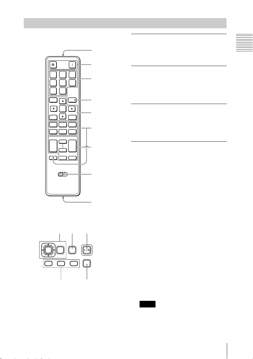
D ZOOM (Digital Zoom) +/– key*1
Enlarges a portion of the image while
projecting.
1Press the D ZOOM + key to display
the digital zoom icon on the projected
image.
2Press the V/v/B/bkeys to move the
digital zoom icon to the point on the
image you wish to enlarge.
3Press the D ZOOM + key or the D
ZOOM – key repeatedly to change the
enlargement ratio. The image can be
enlarged up to 4 times.
Press the RESET key to restore the
previous image.
MUTING key
PIC: Cuts off the image. Press again to
restore the image.
AUDIO: This function is not provided
in this projector.
VOLUME +/– key
This function is not provided in this
projector.
TWIN (double-window) key
This function is not provided in this
projector.
FREEZE key*2
Pauses a projected image. Press again to
restore the image.
*1: Use this key when inputting a
computer signal. But it may not be
enabled, depending on the resolution
of the input signal.
*2: Use this key when inputting a
computer signal.
fSetting the energy–saving mode
easily
ECO MODE key
Energy-saving mode can be set easily,
using a Remote Commander. Energy-
saving mode consists of “Lamp Mode,”
“Power Saving Mode” and “Standby
Mode.”
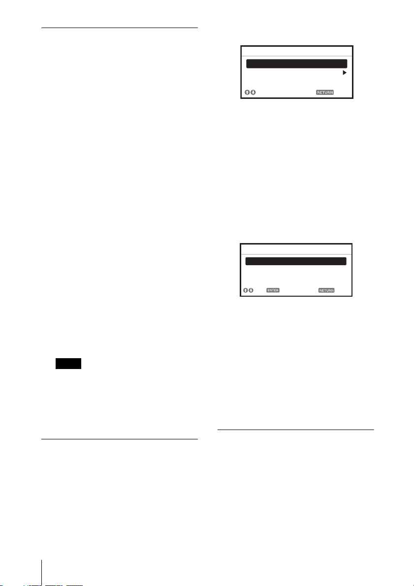
1Press the ECO MODE key to display
the ECO Mode menu.
2Press the V/vkey or ECO MODE key
to select ECO or User mode.
ECO: Sets each mode to the optimum
energy-saving value.
Lamp Mode: Standard
Power Saving Mode: Standby
Standby Mode: Low
(go to step 6)
User: Sets each item of the energy-
saving mode menu as you desire
(go to step 3).
3Select “User” then press the bkey.
The setting items appear.
4Press the V/vkey to select the ECO
Mode item then press the bkey or the
ENTER key.
5Press the V/vkey to select the setting
value.
6Press the RETURN key to restore the
previous image.
For details on ECO Mode settings, see
“Lamp Mode” (page 18) on the Function
menu and “Standby Mode” (page 20)
and “Power Saving Mode” (page 20) on
the Connection/Power menu.
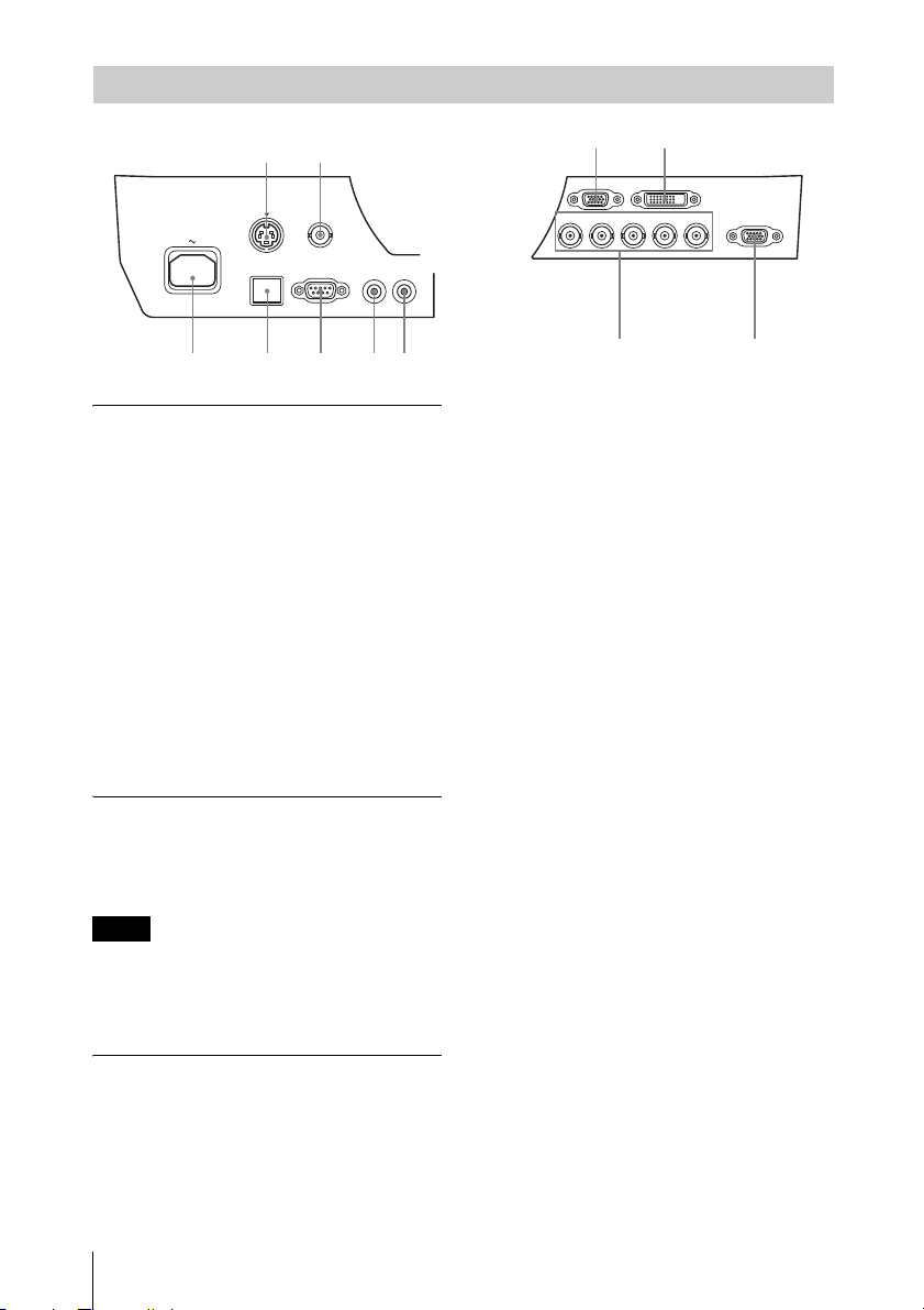
Others
gInfrared transmitter
hID MODE 1/2/3 switch (page 19)
Sets an ID mode of the Remote
Commander. If you assign a different ID
number to each projector when multiple
projectors are used, you can control only
the projector with the same ID mode as
that of the Remote Commander.
Notes
ECO
User
Sel Back
ECO Mode
ECO Mode Menu
Lamp Mode Standard
Power Saving Mode Off
Standby Mode Standard
Sel Back
User
Set

7
Location and Function of Controls
Overview
iCONTROL S output connector
Connects to the CONTROL S input
connector on the projector with a
connecting cable (stereo mini plug (not
supplied)) when using the Remote
Commander as a wired one.
You do not need to install batteries in the
Remote Commander, as the power is
supplied from the projector.
About Remote Commander operation
• Make sure that nothing obstructs the
infrared beam between the Remote
Commander and the remote control
detector on the projector. Direct the
Remote Commander toward the remote
control detector.
• The operation range is limited. The shorter
the distance between the Remote
Commander and the projector is, the wider
the angle within which the Remote
Commander can control the projector
becomes.

8Connecting the Projector
BPreparation
Connecting the Projector
• Use the proper cables for each connection.
• Insert the cable plugs firmly; Loose connections may reduce performance of picture signals or
cause a malfunction. When pulling out a cable, be sure to grip it by the plug, not the cable itself.
• For more information, refer also to the instruction manuals of the equipment you are connecting.
Connection with a computer is explained for each input signal.
INPUT A
For connection when there is some distance between a computer and the projector.
INPUT B
For connecting a computer with an RGB output connector.
• It is recommended that you set the resolution of your computer to 1024 × 768 pixels for the
external monitor.
• To connect a Macintosh computer equipped with a video output connector of a type having two
rows of pins, use a commercially available plug adaptor.
Notes
Connecting a Computer
R/PRG/Y B/PBHD VD
INPUT A
Mini D-sub 15-pin – BNC cable
(not supplied)
RGB output
connector
Computer
Notes
INPUT B RGB
Mini D-sub 15-pin
cable (not supplied)
RGB output
connector
Computer

9
Connecting the Projector
Preparation
INPUT C
For connecting a computer with a DVI-D output connector.
Connections with a VHS video deck, DVD player, or BD player are explained for each input
signal.
S VIDEO IN
For connecting video equipment with an S-video output connector.
VIDEO IN
For connecting video equipment with a video output connector.
Connecting a Video Equipment
INPUT C DVI-D
DVI-D cable
(not supplied)
DVI-D output
connector
Computer
S video cable (not supplied)
S video output
connector
Video equipment
Video – BNC cable
(not supplied)
Video output
connector
Video equipment

10 Connecting the Projector
INPUT A
For connection when there is some long distance between the video equipment and projector.
OUTPUT
Projected images can be output to display equipment such as a monitor.
Output only as a computer signal input from the RGB input connector or a video signal input from
the YPBPRinput connector.
R/PRG/Y B/PB
INPUT A
Component – BNC cable (not supplied)
Video equipment
YPBPRoutput
connector
Connecting an External Monitor
Note
OUTPUT
MONITOR
Mini D-sub 15-pin cable
(not supplied)
RGB input
connector
Display equipment

11
Projecting an Image
Projecting/Adjusting an Image
BProjecting/Adjusting an Image
Projecting an Image
The size of a projected image depends on the distance between the projector and screen. Install
the projector so that the projected image fits the screen size. For details on projection distances
and projected image sizes, see “Projection Distance and Lens Shift Range” (page 45).
1Connect the AC power cord.
2Connect all equipment to the projector
(page 8).
3Turn on the projector.
Press the ?/1key on the projector or the
?key on the Remote Commander.
4Turn on the connected equipment.
5Select the input source.
Press the INPUT key on the projector to
display the input select window. Press
the INPUT key repeatedly or the V/v
key to select an image to be projected.
You can select the input source using
Direct input select keys on the Remote
Commander (page 5).
6Switch your computer to output to
external display by changing your
computer’s setting.
How to switch the computer to output to
the projector varies, depending on the
type of computer.
(Example)
7Adjust the focus, size, and position of
the projected image (page 12).
INPUT
Video
S-Videoo
Input-A
Input-B
Input-C
Sel Skip
Input
Computer
Video equipment
Projector
Wall outlet
1
23
5
4
5
6
+

12 Projecting an Image
Adjusting the tilt of the projector with the adjusters
When the projector is installed on an uneven
surface, you can adjust using the adjusters.
To correct any trapezoidal distortion of the
projected image, use the Keystone feature
(page 5, 21).
And you can also broaden the adjustment
range by removing the nuts from the
adjuster.
Adjusting the Focus, Size, and Position of the Projected image
Focus Size (Zoom) Position (Lens shift)
When attaching the Electric
focus lens
Press the FOCUS key on the
projector or the Remote
Commander then press the B/
bkey (or V/vkey) to adjust
the focus.
When attaching the Manual
focus lens
Turn the Focus Ring to adjust
the focus.
When attaching the Electric
zoom lens
Press the ZOOM key on the
projector or the Remote
Commander then press the B/
bkey (or V/vkey) to adjust
the size.
When attaching the Manual
zoom lens
Turn the Zoom Ring to adjust
the size.
Press the SHIFT key on the
projector or the Remote
Commander then press the V/v/
B/bkey to adjust the position.
To return the lens to the center
position of the projected image
Press the RESET key on the
Remote Commander while
adjusting.

13
Projecting an Image
Projecting/Adjusting an Image
• Be careful not to let the projector down on
your fingers.
• Do not push hard on the top of the projector
with the adjuster extended. It may cause a
malfunction.
• Since the Keystone adjustment is an
electronic correction, the image may be
deteriorated.
Displaying a pattern for adjusting
an image
You can display a pattern for adjusting the
projected image with the PATTERN key on
the Remote Commander. Press the
PATTERN key again to restore the previous
image.
1Press the ?/1key on the main unit or
1key on the Remote Commander.
The message appears if you press the ?/
1key on the main unit. Press it again
according to the message.
2Unplug the AC power cord from the
wall outlet.
After step 1, the fan continues to run for
a while to reduce internal heat. You may
unplug the AC power cord before the fan
stops.
To move the projector just after turning it
off, be sure to wait until the fan stops
before unplugging the AC power cord.
Unplugging the AC power cord before the
fan stops may cause a malfunction.
To erase the confirmation message
The message disappears if you press any key
other than the ?/1key on the main unit or 1
key on the Remote Commander, or if you do
not press any key for a while.
To prevent the confirmation
message from the being displayed
with the key on the main unit
Hold the ?/1key on the main unit pressed
for a few seconds.
Notes Turning Off the Power
Note

14 Using a MENU
BAdjustments and Settings Using a Menu
Using a MENU
The menu displays used for the explanation below may be different depending on the model you are
using.
1Press the MENU key to display the
menu.
2Select the setting menu.
Use the Vor vkey to select the setting
menu then press bor ENTER key.
3Select the setting item.
Use the Vor vkey to select the setting
menu then press bor ENTER key.
To return to the selection screen of the
setting menu, press the Bkey or the
RETURN key.
4Make the setting or adjustment for the
selected item.
Menu operation differs depending on the
setting item. If the next menu window is
displayed, select the item according to
the operations in step 3.
To return to the selection screen of the
setting items, press the Bkey or the
RETURN key. Also, to reset the setting
value of an item to its factory preset
value, press the RESET key during
setting or adjusting.
Using a pop-up menu
Press the V/v/B/bkey to select an item.
Press the ENTER key to restore the
previous screen.
Using the setting menu
Press the Vor vkey to select the item.
Press the ENTER key to restore the
previous screen.
Using the adjustment menu
To increase the number, press the Vor b
key and to decrease the number, press
the vor Bkey. Press the ENTER key to
register the setting. The previous screen
is restored.
5Press the MENU key to clear the
menu.
The menu disappears automatically if no
key is pressed for a while.
Note
Picture Mode Standard
Reset
Contrast 80
Brightness 50
Color 50
Hue 50
Color Temp. Middle
Sharpness 50
Expert Setting
Back
Picture
Sel Set
Setting menu
Picture Mode Standard
Reset
Contrast 80
Brightness 50
Color 50
Hue 50
Color Temp. Middle
Sharpness 50
Expert Setting
Back
Picture
Sel Set
Setting items
Smart APA
CC Display
Pic. Muting Mode Shutter
Lamp Mode Standard
Lamp Light Mode Lamp 1
Background Blue
Start Up Image On
Back
Function
Sel Set
On
Off
Selecting items
Dynamic
Standard
Presentation
Sel Back
Picture Mode
Adjust Back
Contrast
Min
80 Max

15
The Picture Menu
Adjustments and Settings Using a Menu
The Picture Menu
For adjusting the picture for each input signal.
*1: When a computer signal is input, this option is available.
*2: When a video signal is input, this option is available.
*3: When “Picture Mode” is set to the item other than “Presentation,” this option is available.
*4: When a B & W signal is input, this option is not available.
*5: When an analog TV signal is input, this option may not available, depending on the color system.
*6: When a progressive signal is input, this option is not available.
Setting items Functions
Picture Mode Dynamic: Emphasizes the contrast to produce a “dynamic” picture.
Standard: Makes the picture be natural and well balanced.
Presentation*1:Makes the picture bright to suit for a presentation.
Reset The picture settings are initialized to their factory preset values.
Contrast The higher the setting, the greater the contrast. The lower the setting, the lower
the contrast.
Brightness The higher the setting, the brighter the picture. The lower the setting, the darker
the picture.
Color*2 *4 The higher the setting, the greater the intensity. The lower the setting, the lower
the intensity.
Hue*2 *4 *5 The higher the setting, the more greenish the picture becomes. The lower the
setting, the more reddish the picture becomes.
Color Temp.*3 High/Middle/Low: The higher the temperature, the more bluish the picture.
The lower the temperature, the more reddish the picture.
Custom1/ Custom2/ Custom3: An adjusted color temperature setting can be
stored for each item.
The factory settings are Custom1: High, Custom2: Middle, Custom3: Low.
Sharpness*2 The higher the setting, the sharper the picture. The lower the setting, the softer
the picture.
Expert Setting
Film
Mode*2 *6
Auto: Precisely reproduces the image from a film source to suit the original
film source. Normally, select this option.
Off: Select this option if the images are rough around the edges when “Auto” is
selected.
Black Level
Adj.
(Adjust) *2
High/Low/Off: Emphasizes dark portions of the projected image to suit your
taste.
Gamma
Mode*1 Graphics: Improves the reproduction of halftones. Photos can be reproduced
in natural tones.
Text: Contrasts black and white. Suitable for images that contain lots of text.
Notes

16 The Screen Menu
The Screen Menu
For adjusting the size, position, and aspect ratio of the projected image for each input signal.
*1: • Note that if the projector is used for profit or for public viewing, modifying the original picture
by switching to the aspect mode may constitute an infringement of the rights of authors or
producers, which are legally protected.
• Depending on the input signal, setting items for aspect ratio or some other setting items cannot
be set in some cases, or changing the aspect ratio setting may have no effect.
• A part of the image may be displayed in black, depending on the setting item.
*2: Available when a video signal is input from the YPBPRinput connector or the DVI-D input
connector.
*3: Available when a computer signal is input from the RGB input connector.
*4: If the projected image includes large amount of black portion around it, the APA function will
not work properly and a part of the image may not be displayed on the screen and also optimum
image cannot be obtained, depending on the type of input signal. In this case, adjust the “Phase,”
“Pitch,” and “Shift” items manually.
*5: Available when a computer signal is input from the RGB input connector or a video signal is
input from the YPBPRinput connector.
Setting items Functions
Aspect*1 Switches the aspect (page 17).
When the
computer
signal is
input
Normal: Displays the image on the center point of the projected image
without changing the resolution of the input signal or enlarging the image.
Full1: Displays the image to fit the maximum projected image size without
changing the aspect ratio of the input signal.
Full2: Displays the image to fit the maximum projected image size.
When the
video signal
is input
4:3: Displays the image to fit the maximum projected image size with an
aspect ratio fixed to 4:3.
16:9: Displays the image to fit the maximum projected image size with an
aspect ratio fixed to 16:9.
Zoom: Display the center point of the projected image to zoom.
Over Scan*2 On/Off: Hides the outline of the image when set to “On.” Select “On” if
noise appears along the edge of the image.
Adjust Signal Adjusts the image of a computer signal. Use this item if the edge of the
image is cut and reception is bad.
APA*3, *4 Automatically adjusts the projected image to an optimum quality when you
press the ENTER key.
Phase*3 Adjusts the dot phase of the display pixel and the input signal. Set to the
value where looks clearest.
Pitch*3 The higher the setting, the wider the horizontal image elements (pitch). The
lower the setting, the narrower the horizontal image elements (pitch).
Shift*5 H: The higher the setting, the farther right the image is projected on the
screen. The lower the setting, the image farther left.
V: The higher the setting, the farther up the image is projected on the screen.
The lower the setting, the image farther down.
Notes

17
The Screen Menu
Adjustments and Settings Using a Menu
Aspect
*1: If you select “Normal,” the image is
projected in the same resolution as the
input signal without changing the aspect
ratio of the original image.
*2: If you select “Full2,” the image is projected
to fit the projected image size, regardless
of the aspect ratio of the image.
*3: Depending on the input signal, the
projected image may be projected as
illustrated below. In this a case, select
“16:9.”
*4: Depending on the input signal, the image
may be projected as illustrated below. In
this a case, select “Zoom.”
Input signal Recommended
setting value and
projected image
Computer signal
(4:3) (Full1)*1
(16:9) (Full1)*1 *2
(16:10) (Full1)*1 *2
Video signal
(4:3) (4:3)*3
(16:9) (16:9)*4

18 The Function Menu
The Function Menu
The Function menu is used for setting various functions of the projector.
*1: Executes APA when a computer signal is input via the RGB input connector.
Setting items Functions
Smart APA On/Off; When set to “On,” executes APA automatically when a signal is
input.*1
CC Display CC1/CC2/CC3/CC4/Text1/Text2/Text3/Text4: Select the closed caption
service (Captions or Text).
Off: Closed caption does not appear.
Pic.Muting Mode Image: Cuts off the projected image when the PIC MUTING key is
pressed.
Shutter: Cuts off the projected image then close the shutter when the PIC
MUTING key is pressed.
Lamp Mode High/Standard: When set to “High,” the image becomes brighter, and
power consumption becomes higher.
Lamp Light Mode The projector has a function for switching between the two lamps.
When one lamp is turned off, the other is turned on automatically to avoid
interrupt of operation.
Auto: Lights the lamp that is set to be used for shorter duration than the
other when starting up the projector.
Lamp 1/Lamp 2: Lights the selected lamp. If the selected lamp is turn off,
the other is turned on automatically. It is recommended to select this item
when you cannot replace the lamp immediately.
Background Black/Blue: Selects the background color of the projected image when no
signal is input.
Start Up Image On/Off: When set to “On,” the Start Up Image is displayed on the screen
upon startup of the projector.
Note

19
The Operation Menu
Adjustments and Settings Using a Menu
The Operation Menu
The Operation Menu is used for setting for the operations by using the menu or the Remote
Commander.
*1: You will not be able to use the projector if you forget your password. If you call qualified Sony
personnel because you have forgotten the password, you will be asked to verify the projector’s
serial number and your identity. (This process may differ in other countries/regions.) Once your
identity has been confirmed, we will provide you with the password.
Setting items Functions
Language Selects the language used in the menu and on-screen displays.
Status On: All on-screen statuses are enabled.
Off: Turn off the on-screen displays except for the menus, message when
turning off the power, and warning messages.
IR Receiver Front & Rear/Front/Rear: Selects the remote control detectors (IR Receiver)
on the front and rear of the projector.
ID Mode All/1/2/3: Assigns an ID number to the projector. When set to “All,” you can
control the projector with the Remote Commander independently of the
assigned ID Mode. Refer also to “ID MODE 1/2/3 switch” of the Remote
Commander on page 6.
Security Lock*1 On/Off: This function enables restriction of the projector to autherized users
by password. The setting procedures for security locking are as follows:
1Select “On” to display the setting menu.
2Input the password with the MENU, V/v/B/b, and ENTER keys. (The
default password setting is “ENTER, ENTER, ENTER, ENTER.”)
3Input a new password with the MENU, V/v/B/b, and ENTER keys.
4Enter the password again to confirm.
Enter the password when you turn on the projector after disconnecting and
reconnecting the AC power cord.
When it is set to “Off,” you can cancel the security lock. You are required to
input the password again.
If you fail to enter the correct password after three consecutive times, the
projector cannot be used. In this case, press the ?/1key to go Standby mode
then turn on the power again.
Panel Key Lock On/Off: When set to “On,” locks all the control panel keys of the projector.
However, you can operate the following:
• Press and hold the ?/1key for approximately 10 seconds during Standby
mode.
cThe projector turns on.
• Press and hold the MENU key for approximately 10 seconds during power
on.
c“Panel Key Lock” is set to “Off” and enables operation of all control panel
keys on the projector.
Lens Control On/Off: When set to “On,” you can adjusts the lens (Focus, Zoom, and Shift)
from the Remote commander or the projector. To prevent unintentional
operation, set it to “Off” after adjusting the lens.
Note

20 The Connection/Power Menu
The Connection/Power Menu
The Connection/Power menu is used for setting for the connections and power.
*1: The image may not be adjusted properly depending on the type of input signal. In such a case,
adjust it manually to suit to the connected equipment.
*2: When “Standby Mode” is set to “Low,” the network and network control function cannot be
operated while the projector is in standby mode.
Setting items Functions
Network Setting
IP Address Setup Auto (DHCP): The IP address is assigned automatically from the
DHCP server such as a router.
Manual: To specify the IP Address manually.
IP Address/ Subnet
Mask/ Default
Gateway/Primary
DNS/Secondary
DNS
When “Manual” is selected for “IP Address Setup,” select the item
with the bor Bkey and input the value with vor Vkey. When all
items are entered, select Apply then press the ENTER key. The entered
settings will be registered.
Input-A Signal Sel. Auto/Computer/Video GBR/Component: When set to “Auto,”
selects the type of video signal input automatically when “Input-A” is
selected with the INPUT key.*1
Color System Auto/NTSC3.58/PAL/SECAM/NTSC4.43/PAL-M/PAL-N: When set
to “Auto,” selects the color system automatically when “S Video” or
“Video” is selected with the INPUT key.*1
Standby Mode*2 Standard/Low: When set to “Low,” lowers power consumption in
Standby mode.
Power Saving Mode Lamp Cutoff: The lamp turns off automatically and power
consumption is reduced if no signal is input for 10 minutes. The lamp
lights again when a signal is input or any key is pressed. In Lamp
Cutoff, the ON/STANDBY indicator lights in orange (page 26).
Standby: The power will be turned off automatically and the projector
goes to Standby mode if no signal is input for 10 minutes.
Off: The Power Saving Mode is released.
Direct Power On On/Off: When set to “On,” you can turn the power on without going
to Standby mode when the AC power cord is connected to a wall
outlet.
Notes
Other manuals for VPL-FX500L
4
Table of contents
Other Sony Projector manuals

Sony
Sony VPL-PX11 User manual

Sony
Sony BRAVIA VPL-VW60 User manual

Sony
Sony VPL-SW535 Service manual

Sony
Sony VPL-VW1100ES Service manual

Sony
Sony VPL-PX31 User manual

Sony
Sony VPL-MX20 User manual

Sony
Sony SRX-T105 User manual

Sony
Sony HDMI VPL-BW5 User manual

Sony
Sony PL-ES3 User manual

Sony
Sony VPLSW525 User manual

Sony
Sony VPH-D50HTU User manual

Sony
Sony VPL-HW50ES User manual

Sony
Sony VPL-FHZ55 User manual

Sony
Sony SXRD SRX-S110 User manual

Sony
Sony VPL-HW30AES User manual

Sony
Sony VPLGT100 Service manual

Sony
Sony VPL-EX130 User manual

Sony
Sony VPL-FHZ120L Service manual

Sony
Sony VPL-VW528 User manual

Sony
Sony SRX-T110 Reference manual