1
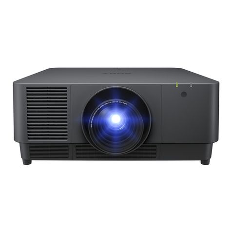
SRX-R320
Table of Contents
2. Adjustment
2-1. Installation of SRX Controller ........................................ 2-2
2-1-1. Installation ............................................................. 2-2
2-1-2. Connection ............................................................. 2-4
2-1-3. Startup and Initialization of SRX Controller ......... 2-5
2-1-4. Startup of This Unit ............................................... 2-7
2-2. Optical Axis Adjustment of Lamp................................... 2-8
2-3. Lens Adjustment (H Shift, V Shift, Zoom, and
Focus Adjustments)....................................................... 2-11
2-4. Illumination Area Adjustment and
Registration Adjustment................................................ 2-13
2-4-1. Illumination Area Adjustment.............................. 2-13
2-4-2. Registration Adjustment ...................................... 2-17
2-5. Screen Illuminance Setting and Color Space Conversion
(CSC Adjustment) ......................................................... 2-18
2-6. Field Angle Adjustment................................................. 2-28
2-6-1. Side Masking ....................................................... 2-28
2-6-2. Height Masking.................................................... 2-31
2-7. Setting of Function Memory ......................................... 2-33
2-7-1. Setting of New Function Memory ....................... 2-33
2-7-2. Change in Setting of Registered Function
Memory................................................................ 2-35
2-7-3. Copying of Registered Function Memory to
Create New Function Memory ............................ 2-36
2-7-4. Switching of Registered Function Memory......... 2-37
2-8. How to Use the SRX Controller.................................... 2-38
2-8-1. Configuration ....................................................... 2-38
2-8-2. Function Memory ................................................ 2-38
2-8-3. Functions of Each Window.................................. 2-39
3. Error Message
Manual Structure
Purpose of this manual.................................................................. 3
Related manuals............................................................................ 3
Trademarks.................................................................................... 3
1. Installation
Outline........................................................................................ 1-1
1-1. Removing/Installing the Cabinet Panel........................... 1-1
1-1-1. Name of Cabinet Panel .......................................... 1-1
1-1-2. Panel (U7) Block Assembly................................... 1-2
1-1-3. Panel (U2) Block Assembly................................... 1-2
1-1-4. Panel (U3) .............................................................. 1-3
1-1-5. Panel (U6) .............................................................. 1-3
1-1-6. Panel (U5) .............................................................. 1-4
1-1-7. Panel (U1B) ........................................................... 1-4
1-1-8. Panel (U1) .............................................................. 1-5
1-1-9. Panel (U4) Block Assembly................................... 1-6
1-1-10. Panel (U4B) ........................................................... 1-7
1-1-11. Panel (U8) .............................................................. 1-8
1-2. Tilt Angle Adjustment .....................................................1-9
1-3. Installing the Duct ......................................................... 1-11
1-4. Installing the Projection Lens........................................ 1-12
1-5. Installing the Lens Cover .............................................. 1-13
1-6. Installing the Status Light Assembly............................. 1-14
1-7. Installing the Touch Panel Adapter ............................... 1-15
1-8. Installing the Lamp Bulb............................................... 1-17
1-9. Installing LMT-300 and Connecting with the Unit....... 1-23
1-10. Installing the Optional Board to INPUT A and
INPUT B ....................................................................... 1-27
1-11. Interlock Terminal ......................................................... 1-33
1-12. Connecting and Wiring of External Device .................. 1-35
1-13. Connecting the Power Cord .......................................... 1-36
1-14. Dimensions ................................................................... 1-38

