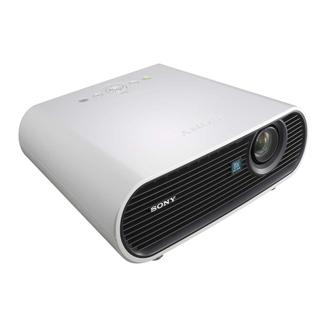
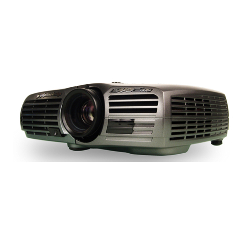
Sony VPL-PX41 User manual

DATA PROJECTOR
VPL-PX41
PROJECTION LENS (AVAILABLE SEPARATELY)
VPLL-FM22
PROJECTION LENS (AVAILABLE SEPARATELY)
VPLL-ZM102
PROJECTION LENS (AVAILABLE SEPARATELY)
VPLL-ZM32
REMOTE COMMANDER
RM-PJM17
SERVICE MANUAL
1st Edition

VPL-PX41
!WARNING
This manual is intended for qualified service personnel only.
To reduce the risk of electric shock, fire or injury, do not perform any servicing other than that
contained in the operating instructions unless you are qualified to do so. Refer all servicing to
qualified service personnel.
!WARNUNG
Die Anleitung ist nur für qualifiziertes Fachpersonal bestimmt.
Alle Wartungsarbeiten dürfen nur von qualifiziertem Fachpersonal ausgeführt werden. Um die
Gefahr eines elektrischen Schlages, Feuergefahr und Verletzungen zu vermeiden, sind bei
Wartungsarbeiten strikt die Angaben in der Anleitung zu befolgen. Andere als die angegeben
Wartungsarbeiten dürfen nur von Personen ausgeführt werden, die eine spezielle Befähigung
dazu besitzen.
!AVERTISSEMENT
Ce manual est destiné uniquement aux personnes compétentes en charge de l’entretien. Afin
de réduire les risques de décharge électrique, d’incendie ou de blessure n’effectuer que les
réparations indiquées dans le mode d’emploi à moins d’être qualifié pour en effectuer d’autres.
Pour toute réparation faire appel à une personne compétente uniquement.
CAUTION
RISK OF EXPLOSION IF BATTERY IS REPLACED BY AN INCORRECT TYPE.
DISPOSE OF USED BATTERIES ACCORDING TO THE INSTRUCTIONS.

1
VPL-PX41
Table of Contents
1. Service Information
1-1. Appearance Figure ...................................................................................... 1-1
1-2. Board Locations .......................................................................................... 1-1
1-3. Disassembly ................................................................................................ 1-2
1-3-1. Top Cover Assy and Hood Assy ................................................ 1-2
1-3-2. Projection Lens........................................................................... 1-3
1-3-3. C Board ...................................................................................... 1-3
1-3-4. NR Board ................................................................................... 1-4
1-3-5. Side Panel Block Assy and H Board .......................................... 1-5
1-3-6. Bracket 92 and DC Fan 1 ........................................................... 1-6
1-3-7. GA Board, GB Board and Bracket (G) ...................................... 1-6
1-3-8. OPT UNIT Assy and Lamp Box ................................................ 1-7
1-3-9. Prism Block Assy ....................................................................... 1-7
1-3-10. Bracket (BS), DC Fan 2 and Fan 1 ............................................ 1-8
1-3-11. Lamp Power Supply Block and V Board ................................... 1-9
1-3-12. Fan 2 and U Board ..................................................................... 1-9
1-3-13. F Board ..................................................................................... 1-10
1-3-14. DC Fan 3 .................................................................................. 1-10
1-4. Extension Boards and Extension Cables ................................................... 1-11
1-4-1. Connection ............................................................................... 1-12
1-5. Warning on Power Connection ................................................................. 1-12
1-6. Service Mode (Network) ........................................................................... 1-13
1-6-1. How to Enter the Service Mode ............................................... 1-13
1-7. Update Function ........................................................................................ 1-14
1-8. Event Trace Function ................................................................................ 1-14
1-8-1. INFORMATION ...................................................................... 1-14
1-8-2. EVENT TRACE....................................................................... 1-14
1-9. Network Reset ........................................................................................... 1-16
1-9-1. Reset item ................................................................................. 1-16
1-9-2. Reset procedure ........................................................................ 1-16
1-10. RTC Battery Replacement ........................................................................ 1-16
1-11. Web Password Change .............................................................................. 1-16
2. Electrical Adjustments
2-1. Preparation .................................................................................................. 2-1
2-1-1. Required Equipment................................................................... 2-1
2-1-2. How to Enter the Factory Mode ................................................. 2-1
2-2. V COM Adjustment .................................................................................... 2-1
2-3. Initial Values of Adjustment Items ............................................................. 2-2
2-4. Service Know-How ..................................................................................... 2-9
2-4-1. When the Prism Block Is Replaced ............................................ 2-9
2-4-2. When the C Board Is Replaced .................................................. 2-9
2VPL-PX41
2-5. White Balance Adjustment ......................................................................... 2-9
2-5-1. HIGH Mode of INPUT-D .......................................................... 2-9
2-5-2. LOW Mode of INPUT-D ......................................................... 2-10
2-5-3. HIGH Mode of VIDEO ............................................................ 2-10
2-5-4. LOW Mode of VIDEO ............................................................. 2-10
2-6. Memory Structure ..................................................................................... 2-11
3. Semiconductors
4. Spare Parts
4-1. Notes on Repair Parts .................................................................................. 4-1
4-2. Exploded Views .......................................................................................... 4-2
4-3. Electrical Parts List ................................................................................... 4-18
5. Block Diagrams
Overall (1/2) ........................................................................................................... 5-1
Overall (2/2) ........................................................................................................... 5-2
C (1/5), Q (1/4) ....................................................................................................... 5-3
C (2/5), Q (2/4) ....................................................................................................... 5-4
C (3/5), Q (3/4) ....................................................................................................... 5-5
C (4/5), Q (4/4), U, V, NR, H ................................................................................. 5-6
C (5/5) ..................................................................................................................... 5-7
F, GA, GB............................................................................................................... 5-8
6. Diagrams
6-1. Frame Schematic Diagrams ........................................................................ 6-2
Frame Wiring (1/2) ................................................................................... 6-2
Frame Wiring (2/2) ................................................................................... 6-3
6-2. Schematic Diagrams and Printed Wiring Boards........................................ 6-4
Schematic Diagrams
Q (1/9) ....................................................................................................... 6-6
Q (2/9) ....................................................................................................... 6-7
Q (3/9) ....................................................................................................... 6-8
Q (4/9) ....................................................................................................... 6-9
Q (5/9) ..................................................................................................... 6-10
Q (6/9) ..................................................................................................... 6-11
Q (7/9) ..................................................................................................... 6-12
Q (8/9) ..................................................................................................... 6-13

3
VPL-PX41
Q (9/9) ..................................................................................................... 6-14
C (1/19) ................................................................................................... 6-17
C (2/19) ................................................................................................... 6-18
U .............................................................................................................. 6-18
V .............................................................................................................. 6-18
NR ........................................................................................................... 6-18
C (3/19) ................................................................................................... 6-19
C (4/19) ................................................................................................... 6-20
C (5/19) ................................................................................................... 6-21
C (6/19) ................................................................................................... 6-22
C (7/19) ................................................................................................... 6-23
C (8/19) ................................................................................................... 6-24
C (9/19) ................................................................................................... 6-25
C (10/19) ................................................................................................. 6-26
C (11/19) ................................................................................................. 6-27
C (12/19) ................................................................................................. 6-28
C (13/19) ................................................................................................. 6-29
C (14/19) ................................................................................................. 6-30
C (15/19) ................................................................................................. 6-31
C (16/19) ................................................................................................. 6-32
C (17/19) ................................................................................................. 6-33
C (18/19) ................................................................................................. 6-34
C (19/19) ................................................................................................. 6-35
GA ........................................................................................................... 6-39
GB (1/3) .................................................................................................. 6-42
GB (2/3) .................................................................................................. 6-43
GB (3/3) .................................................................................................. 6-44
F .............................................................................................................. 6-47
H .............................................................................................................. 6-47
Printed Wiring Boards
Q ................................................................................................................ 6-4
C .............................................................................................................. 6-36
GA ........................................................................................................... 6-38
GB ........................................................................................................... 6-40
F .............................................................................................................. 6-46
NR ........................................................................................................... 6-46
U .............................................................................................................. 6-46
V .............................................................................................................. 6-46
H .............................................................................................................. 6-47


1-1
VPL-PX41
Section 1
Service Information
1-2. Board Locations
Power Supply Block (Lamp)
C
Q
H
GB
GA
U
NR
V
F
1-1. Appearance Figure

1-2 VPL-PX41
1-3. Disassembly
1-3-1. Top Cover Assy and Hood Assy
1Special screw (+PSW M3x90)
3Five screws (+PSW M3x8)
4Hood assy
2Slide the (2) Hood assembly
to the front and remove it
by raising upward.

1-3
VPL-PX41
1-3-2. Projection Lens
1Four screws (+PSW M3x10)
2Projection lens
1-3-3. C Board
1Six screws (+PSW M3x8)
2C board
CN852 CN802
CN752
CN402
Q board
CN152
CN901
CN902
CN154
CN157
CN151
CN156
CN155
CN702
CN701

1-4 VPL-PX41
1Screw (+PSW M3x8)
2Screw (+PSW M3x8)
3Filter (RE)
4Two nylon rivets
5NR board
CN154
C board
1-3-4. NR Board

1-5
VPL-PX41
1-3-5. Side Panel Block Assy and H Board
*To remove the side panel block assy and H board, remove the C board beforehand.
1Two screws (+PSW M3x8)
2Side panel block assy
7Two screws (+BTB 3x12)
8Screw (+BTB 3x12)
6Eight screws
3Screw
(+PSW M3x8)
9Four screws (+PSW M3x8)
!- Four screws
(+PSW M3x8)
5Two screws (DVI)
4Plate Q
0Q board

1-6 VPL-PX41
1-3-6. Bracket 92 and DC Fan 1
*To remove the bracket 92 and DC fan 1, remove the C board beforehand.
1Three screws (+PSW M3x8)
4Two screws (+PSW M3x8)
6Two screws (+PSW 3x10)
7DC fan 1
Plate (net)
3Plate (GAC) assy
2Bracket (GB)
5Bracket (92)
CN303
1-3-7. GA Board, GB Board and Bracket (G)
*To remove the GA board, GB board and bracket (G), remove the C board beforehand.
When installing,
top of the GB board should
be inserted in the groove
of the bracket. GB board
Groove
A
1Three screws (+PSW M3x8)
5Two screws (+PSW M3x8)
7Two screws (+PSW M3x8)
8GA board
4GB board
2Bracket (GB)
3Plate (GAC) assy
CN101
CN303
CN302
CN301
CN403
CN402
CN401
CN104
6While unlocking the claws
that are locked on the hook
of the portion A,
remove this bracket (G).

1-7
VPL-PX41
1-3-8. OPT UNIT Assy and Lamp Box
*To remove the optics block assy, remove the C board beforehand.
1Open the lamp door
on the back of the main unit
and loosen this screw fully.
!/ Lamp box
2Screw (+B 3x8)
6Two screws
(+PSW M3x8)
8Four screws
(+PSW M3x8)
9OPT UNIT assy
3Thermostat
7Lamp house,
Plate (LMP)
4Two screws
(+PSW 3x10)
5Cord
(Lamp power supply block)
1Three screws (+B 3x8)
4Two screws (+B 3x8)
2Shade plate
3Prism retainer
5Prism block assy
1-3-9. Prism Block Assy
*To remove the prism block assy, remove the C board beforehand.

1-8 VPL-PX41
1Four screws (+PSW M3x8)
3Two screws (+PSW M3x8)
8Three screws
(+PSW M3x8)
5Duct (TP)
9Duct (BT)
0Connector
!- D.C. Fan 1
6Connector
7D.C. fan 2
4Claw
2Bracket (BS)
1-3-10. Bracket (BS), DC Fan 2 and Fan 1
*To remove the bracket (BS), DC fan 2 and fan 1, remove the C board, bracket 92 and GB board beforehand.

1-9
VPL-PX41
1-3-11. Lamp Power Supply Block and V Board
*To remove the lamp power supply block and V board, remove the C board, bracket 92 and GB board beforehand.
5Two screws (+PSW 3x10)
7Two screws
(+PSW M3x8)
1Screw (+PSW M3x8)
3Screw
(+PSW M3x8)
4Thermostat
8Lamp power supply block
6Cord (Lamp power supply block)
9Sheet (BS)
2V board
CN1
CN2
0Plate (BS)
CN3
1Three screws (+PSW M3x8)
3Two screws (+PSW M3x8)
2Lamp duct
4Rear guide
7Screw (+PSW M3x8)
8U board
CN1
5Connector
6D.C. Fan 2
1-3-12. Fan 2 and U Board
*To remove the fan 2 and U board, remove the C board, optical block assy and lamp box beforehand.

1-10 VPL-PX41
1-3-13. F Board
*To remove the F board, remove the C board, OPT UNIT assy, lamp box and bracket (G) beforehand.
1Two screws (+PSW 4x8)
2Two screws (+PSW M3x8)
4F board
3Sheet (F)
CN502
CN501
1-3-14. DC Fan 3
*To remove the DC fan 3, remove the C board, OPT UNIT assy, lamp box, lamp duct, bracket 92, bracket (BS) and
bracket (G) beforehand.
1Two screws (+PSW M3x8)
2Plate (GA)
3DC fan 3

1-11
VPL-PX41
1-4. Extension Boards and Extension Cables
X40 board
X70 board x 6 XF board x 3
Cable 3P (X40-C) x 2
Flat cable 24P (X70) x 9
Cable 4P (X40-C) x 1
Cable 10P (X40-C) x 1
Cable 12P (X40-C) x 1
Cable 2P (X40-C) x 1
Cable 4P (C157short connector) x 1
Flat cable 32P (C-XF) x 1
X kit ass
y
(
A-1604-232-A
)

1-12 VPL-PX41
Cable (4P)
(C board : CN157)
Cable (4P)
(C board : CN151
- X40 board : CN14)
Cable (2P)
(C board : CN902
- X40 board : CN13)
Cable (2P)
(C board : CN901
- X40 board : CN12)
Cable (2P)
(C board : CN152
- X40 board : CN11)
Cable (10P)
(C board : CN156
- X40 board : CN15)
Cable (12P)
(C board : CN155
- X40 board : CN16)
Flat cable (32P)
(C board : CN852 - XF board)
Flat cable (32P)
(C board : CN801 - XF board)
Flat cable (32P)
(C board : CN752 - XF board)
Q board : CN402
Q board
: CN702
CN101 CN101CN103 CN103
CN104 CN104CN102 CN102CN105 CN105
C
NR
X70 X70
X40
XF
CN252
CN251
CN253
Q board
: CN701
Flat cables (24P)
1-4-1. Connection
1-5. Warning on Power Connection
Use a proper power cord for your local power supply.
The United States, Continental UK, Ireland, Japan
Canada Europe Australia, New Zealand
Plug type VM0233 290B YP-12A COX-07 _1) YP332
Female end VM0089 386A YC-13B COX-02 VM0310B YC-13
Cord type SJT SJT H05VV-F H05VV-F N13237/CO-228 VCTF
Rated Voltage & Current 10A/125V 10A/125V 10A/250V 10A/250V 10A/250V 7A/125V
Safety approval UL/CSA UL/CSA VDE VDE VDE DENAN
Cord length (max.) 4.5m (177 1/4 inches) _
1) Use the correct plug for your country.

1-13
VPL-PX41
When you are asked your user name and password, enter as follows:
User name: service
Password: vpl-px41
n
When you move from the Service mode to another page and enter the Service mode again, close the Web
browser and launch it again.
Fig. 1. Index screen
1-6. Service Mode (Network)
In the VPL-PX41, the Event Trace function, which updates the network firmware or displays the error
logs of the projector and others, can be used in the Service mode by connecting to the network.
This section describes that procedure.
1-6-1. How to Enter the Service Mode
To use the functions exclusive for Service, the VPL-PX41 needs to enter the Service mode. To enter the
Service mode, enter the following address to the Web browser (IE5.0 or later):
http://IP ADDRESS/service (Enter the projector’s IP address in “IP ADDRESS”.)
Fig. 2. Service screen

1-14 VPL-PX41
1-7. Update Function
The Update function updates the network firmware.
Main software or scaler cannot be updated by this.
1-8. Event Trace Function
1-8-1. INFORMATION
If you click the [Event Trace] tab in the Web page of the Service, you can verify the following
information in the INFORMATION area.
Model Name: Model name
Serial No.: Serial number
Location: Installed location (displayed blank if this is not set)
ROM Ver.: ROM versions of Main, Scaler1, and IP
Fig. 3. Event Trace screen
1-8-2. EVENT TRACE
Following are the descriptions of each one of the displayed items.
(1) TIMER
Lamp Timer: Lamp use time
Operation Timer: Operation time
(2) LAMP TIMER RESET LOG
DATE: Year, month, and date when the lamp timer is reset
Operation Timer: Operation time
Lamp Timer: Lamp use time immediately before it is reset.
Other manuals for VPL-PX41
3
Table of contents
Other Sony Projector manuals

Sony
Sony VPH-1272Q User manual

Sony
Sony VPL-VW520ES Service manual

Sony
Sony VPL-CX100 Reference guide

Sony
Sony VPL-SW235 Service manual

Sony
Sony VPD-MX10 User manual

Sony
Sony VPL-HW65 User manual

Sony
Sony KP-46V25 Instruction Manual

Sony
Sony HDMI VPL-FE40 User manual

Sony
Sony VPL-HS10 Marketing Specifications & Features User manual

Sony
Sony VPL-CS21 User manual

Sony
Sony VPL-SX12 User manual

Sony
Sony VPLGH10 User manual

Sony
Sony Super Bright VPH-1000Q User manual

Sony
Sony KP-46XBR35 User manual

Sony
Sony VPLFH36/B User manual

Sony
Sony VPL-X1000U User manual

Sony
Sony VPL-HS50 User manual

Sony
Sony VPH-G70Q User manual

Sony
Sony RM-PJ25 User manual

Sony
Sony KP 53HS10 User manual