1
VPL-ES7
Table of Contents
1. Service Overview
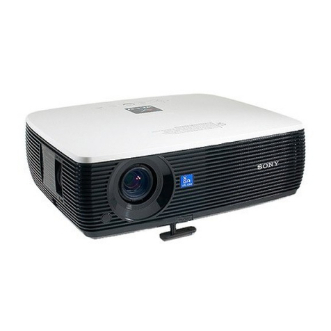
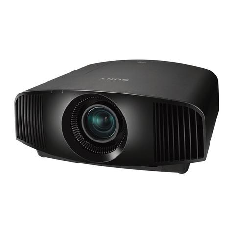
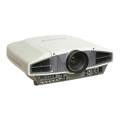
1-1. Appearance Figure .......................................................... 1-1
1-2. Board Location................................................................ 1-1
1-3. Disassembly .................................................................... 1-2
1-3-1. Upper Case Assembly............................................ 1-2
1-3-2. Rear Case Pack Assembly...................................... 1-3
1-3-3. Main Board ............................................................ 1-3
1-3-4. Power Board and Thermal Sensor Board .............. 1-4
1-3-5. Front Case Assembly and IR Sensor Board...........1-5
1-3-6. Fan (Exhaust)-1...................................................... 1-5
1-3-7. Fan (Exhaust)-2...................................................... 1-6
1-3-8. Optional Unit Assembly ........................................ 1-7
1-3-9. Lamp Power Supply...............................................1-8
1-3-10. Fan ......................................................................... 1-9
1-4. 3D GAMMA Service Tool Application Software ......... 1-10
1-5. Indicator ........................................................................ 1-10
1-6. Circuit Description ........................................................ 1-11
1-7. Replacing Fuse .............................................................. 1-13
1-8. Connecting/Disconnecting the Flexible Card Wire.......1-14
1-9. Lead-free Solder............................................................ 1-14
2. Electrical Adjustments
2-1. Preparation ...................................................................... 2-1
2-1-1. Required Equipment .............................................. 2-1
2-1-2. How to Enter the Service Mode............................. 2-1
2-2. Adjustment of Main Board When it is Replaced ........... 2-1
2-2-1. Save the Optical Data and Replacement................2-1
2-3. EEPROM Replacement................................................... 2-2
2-4. ADC Calibration ............................................................ 2-2
2-4-1. RGB Alignment Procedure .................................... 2-2
2-4-2. YUV Alignment Procedure ................................... 2-3
2-5. V COM Adjustment ........................................................ 2-4
2-6. White Balance Adjustment.............................................. 2-6
2-6-1. HIGH Mode of PC ................................................ 2-6
2-6-2. MIDDLE Mode of PC .......................................... 2-6
2-6-3. LOW Mode of PC .................................................2-7
2-6-4. HIGH Mode of VIDEO ......................................... 2-7
2-6-5. MIDDLE Mode of VIDEO....................................2-8
2-6-6. LOW Mode of VIDEO ..........................................2-8
2-7. Others .............................................................................. 2-9
2-7-1. Note When Replacing the Main Board..................2-9
2-7-2. Status Information................................................ 2-10
2-7-3. ADC Calibration Value........................................ 2-10
2-8. Memory Structure ......................................................... 2-11
2-9. Initial Values of Adjustment Items ................................ 2-13
3. Troubleshooting
4. Spare Parts
4-1. Notes on Repair Parts...................................................... 4-1
4-2. Exploded Views............................................................... 4-2
4-3. Electrical Parts List ......................................................... 4-4
4-4. Packing Materials & Supplied Accessories.................... 4-4
5. Block Diagrams
Overall (VPL-ES7).......................................................... 5-1
Overall (VPL-EX70) ....................................................... 5-2
Overall (VPL-EX7) ......................................................... 5-3
Overall (VPL-EX7IN)..................................................... 5-4
6. Schematic Diagrams
Frame Wiring (VPL-ES7) ............................................... 6-1
Frame Wiring (VPL-EX70)............................................. 6-2
Frame Wiring (VPL-EX7)............................................... 6-3
Frame Wiring (VPL-EX7IN) .......................................... 6-4

