7
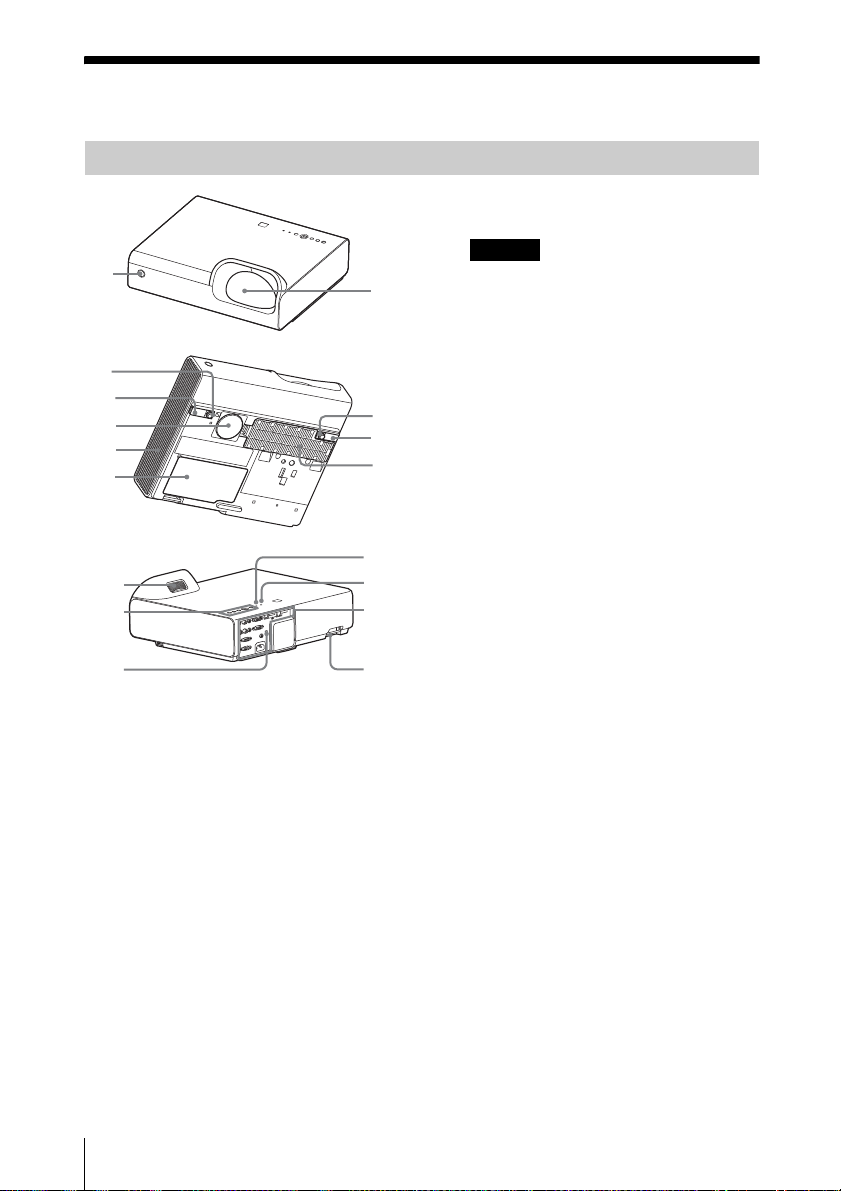
Location and Function of Controls
Overview
*1: Use this key when inputting a
computer signal. But it may not be
used depending on the resolution of
the input signal.
*2: Use this key when inputting a
computer signal.You cannot use this
key when “Type A USB”, “Type B
USB”or “Network”is selected as the
input.
fSetting the energy–saving mode
easily
ECO MODE key
Energy-saving mode can be set easily.
Energy-saving mode consists of “Lamp
Mode,” “With No Input,” “With Static
Signal” and “Standby Mode.”
1Press the ECO MODE key to display
the ECO Mode menu.
2Press the V/vkey or ECO MODE key
to select “ECO” or “User” mode.
ECO: Sets each mode to the optimum
energy-saving value.
Lamp Mode: Low
With No Input: Standby
With Static Signal: Lamp
Dimming
Standby Mode: Low
User: Sets each item of the ECO
Mode menu as you desire (go to
step 3).
3Select “User” then press the bkey.
The setting items appear.
4Press the V/vkey to select the item
then press the ENTER key.
5Press the V/vkey to select the setting
value.
6Press the ENTER key.
The screen returns to the User screen.
For details on ECO Mode settings, see
“Lamp Mode,” “Constant Brightness,”
“With No Input,” “With Static Signal”
and “Standby Mode” on the Connection/
Power menu (page 26).
If you set “ECO Mode” to “ECO,” or
“Standby Mode”(in “User”) to “Low,”
the network control function will be
disabled in standby mode. If the external
control is being performed by using the
network or network control function, do
not select “ECO,” or do not set “Standby
Mode” ( in “User”) to “Low.”
Others
gInfrared transmitter
About remote commander operation
• Direct the remote commander toward the
remote control receiver.
• The shorter the distance between the
remote commander and the projector is,
the wider the angle within which the
remote commander can control the
projector becomes.
• Make sure that nothing obstructs the
infrared beam between the remote
commander and the remote control
receiver on the projector.
Notes
RETURN
ECO
User
ECO Mode
:Sel :Back
RETURN
Lamp Mode High
Constant Brightness
Auto Power Saving
Standby Mode
Off
ON
With No Input
Lamp Dimming
With Static Signal
Standard
User
:Sel :Set :Back
Note